Root barrier systems are used in urban construction to control root growth near pavements, utility corridors, retaining edges, landscaped podiums, and civil infrastructure. A reliable system is not only a buried sheet. It requires suitable polymer selection, controlled thickness, smooth bedding, sealed joints, drainage planning, and maintenance records. HDPE geomembrane or rigid HDPE root barrier sheets are often selected where stiffness, puncture resistance, and chemical stability are required. LLDPE geomembrane may be considered where the subgrade is irregular or settlement movement is expected. PET non-woven geotextile can be added as a protection or separation layer where angular fill, gravel, or drainage aggregate may damage the membrane surface.
Puncture Strength
Puncture strength in urban root barrier systems depends on membrane thickness, polymer stiffness, subgrade smoothness, seam quality, and protection during backfilling. For civil landscaping, road verges, utility corridors, and paved areas, HDPE geomembrane or rigid HDPE root barrier sheets are commonly selected when root pressure, compacted soil, gravel bedding, or nearby hard structures may create concentrated stress. Typical barrier thickness may range from about 0.75 mm to 2.0 mm, with higher thickness used near aggressive root zones, retaining edges, or service trenches. Installation control should focus on stone removal, compacted bedding, overlap width, weld continuity, and inspection before soil cover is placed.
Root Pressure and Material Thickness
Root pressure is not only a biological issue. In urban construction, it becomes a material loading condition because roots expand against concrete edges, asphalt layers, retaining walls, utility ducts, and compacted soil. A thin barrier may stop fine roots at first, but it can deform, crease, or tear when root pressure combines with sharp aggregate or settlement movement.
For root barrier systems, HDPE geomembrane is often used where stiffness, puncture resistance, and chemical stability are required. LLDPE geomembrane may be considered where the barrier must tolerate more movement, irregular subgrade, or local settlement. Selection should not be based on thickness alone. Polymer type, tensile behavior, seam method, backfill material, and installation damage risk also affect field performance.
| Site Condition | Practical Material Direction | Thickness Consideration |
|---|---|---|
| Tree pits near sidewalks | HDPE root barrier or HDPE geomembrane | Medium to higher thickness for root pressure and pavement edge contact |
| Utility corridors | HDPE geomembrane with controlled seams | Selected according to trench bedding, backfill material, and service access |
| Irregular soil or settlement-prone areas | LLDPE geomembrane may be suitable | Flexibility may matter more than stiffness alone |
| Gravel backfill or angular stone risk | Geomembrane with PET non-woven geotextile protection | Higher puncture resistance and surface cushioning are needed |
| Deep root redirection zones | HDPE barrier sheet or geomembrane | Barrier depth and vertical continuity must match root growth risk |
A practical specification should define:
- material type, such as HDPE, LLDPE, or structured root barrier sheet;
- nominal thickness, commonly selected within about 0.75 mm to 2.0 mm depending on site risk;
- puncture resistance test reference, such as ASTM D4833 or project-equivalent testing;
- tensile and tear resistance requirements;
- seam type, overlap width, and repair method;
- protection layer requirements where angular fill or gravel is used.
For paved urban areas, the barrier should extend deep enough to redirect roots below the pavement base or away from service lines. A shallow barrier can allow roots to pass underneath and reappear near slabs, curbs, or drainage channels. Depth should be coordinated with tree species, soil profile, pavement structure, and local arboricultural requirements.
Material thickness should increase when one or more of these conditions are present:
- large tree species with strong lateral root development;
- narrow planting strips beside roads or walkways;
- compacted subgrade with limited root space;
- angular gravel or recycled aggregate near the barrier;
- mechanical compaction during backfilling;
- nearby utilities that cannot tolerate root intrusion;
- long service design periods with limited access after installation.
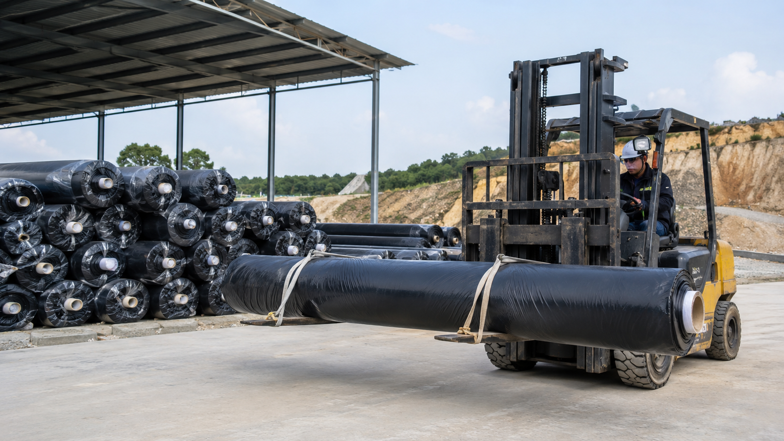
The barrier should not be folded sharply during installation. A sharp fold can create a stress line that weakens the sheet and reduces resistance to root pressure. Rolls should be stored flat or supported, lifted without dragging, and placed before heavy site traffic begins.
Subgrade Preparation and Surface Protection
Puncture resistance in the field is often controlled by the surface under the barrier, not only by the membrane itself. A geomembrane placed directly over stones, broken concrete, exposed rebar, compacted rubble, or sharp roots can be damaged during backfilling before the tree root system reaches it.
Before installation, the subgrade should be prepared as an inspection surface. The surface should be smooth, stable, and free from objects that create point loading. In utility trenches, the bedding layer must be checked carefully because narrow working space increases the chance of hidden stones and tool damage.
A basic installation control sequence is:
- Remove stones, roots, metal fragments, broken concrete, and sharp debris.
- Grade the soil to avoid voids beneath the barrier.
- Compact the base evenly without creating hard ridges.
- Place a sand bedding layer or fine soil layer where required.
- Install the geomembrane without dragging it across rough ground.
- Inspect the visible surface before backfilling.
- Use controlled backfill placement instead of dumping angular material directly onto the sheet.
For high puncture-risk sites, a PET non-woven geotextile protection layer can be used with the geomembrane. The geotextile helps reduce concentrated pressure from stones, roots, and backfill movement. It does not replace the root barrier. It protects the barrier surface.
| Site Risk | Recommended Control |
|---|---|
| Angular gravel backfill | Add geotextile protection between gravel and geomembrane |
| Broken concrete or demolition fill | Remove unsuitable material before barrier placement |
| Utility trench with narrow access | Use pre-installation surface inspection and controlled backfilling |
| Tree pit beside pavement | Protect the upper edge from curb, slab, and compaction damage |
| Mechanically compacted backfill | Limit direct compaction pressure near exposed membrane |
The upper edge of the barrier needs attention. In urban landscapes, damage often occurs at the exposed or near-surface zone where maintenance tools, edging work, pavement repair, and soil settlement happen. The top edge should be fixed, capped, or buried according to the design so that roots do not pass over it and tools do not cut into it.
During backfilling, workers should avoid:
- dropping large stones directly onto the barrier;
- using sharp shovels against the membrane;
- compacting directly on exposed geomembrane without cover;
- leaving wrinkles that can trap stress;
- allowing the barrier to slide out of alignment;
- placing organic debris against seams or corners.
| Inspection Item | Acceptance Direction |
|---|---|
| Subgrade surface | Smooth, firm, and free of sharp objects |
| Barrier surface | No cuts, holes, heavy scratches, or fold damage |
| Protection layer | Continuous where specified, with no exposed puncture points |
| Backfill material | Fine soil or approved fill near the membrane surface |
| Upper edge | Fixed or covered to reduce root bypass and tool damage |
| Final alignment | Barrier remains vertical or at the designed angle |
Surface protection matters most before the system is buried. Once soil, pavement, or landscaping is installed, hidden punctures are difficult to locate without excavation. Inspection should therefore happen before cover placement, after partial backfill, and after final grading.
Seam Strength and Overlap Control
Seams are vulnerable if they are poorly aligned, under-welded, contaminated, or placed under tension. Root barrier systems must maintain continuity because roots usually exploit openings, gaps, folds, and unsealed overlaps. A strong sheet with weak seams can still fail as a barrier.
For geomembrane-based root barrier systems, seam method depends on material and site layout. HDPE and LLDPE geomembranes are usually joined by thermal welding methods such as wedge welding or extrusion welding. Small root barrier panels may also use mechanical joining systems, but the joint must remain tight and continuous under soil pressure.
The overlap width should be defined in the project specification. In field practice, overlaps are commonly controlled within a practical range such as 75 mm to 150 mm, depending on material thickness, welding equipment, seam type, and manufacturer guidance. The exact overlap should follow the approved method statement.
Seam control should include:
- clean overlap surfaces with no soil, moisture, oil, or organic debris;
- correct welding temperature and travel speed for the polymer type;
- stable sheet alignment before welding;
- no sharp wrinkles inside the overlap;
- trial welds when site temperature changes;
- visual inspection of seam continuity;
- repair patches over cuts, holes, fish-mouths, and incomplete welds.
| Seam Issue | Field Risk | Control Method |
|---|---|---|
| Insufficient overlap | Root entry through joint movement | Mark overlap lines before welding |
| Soil inside seam area | Poor weld contact | Clean and dry surfaces before joining |
| Wrinkles at overlap | Stress concentration and gaps | Reposition sheet before welding |
| Incomplete weld | Water, soil, and root entry path | Use visual checks and project-required seam testing |
| Poor corner detailing | Root bypass around vertical edges | Use fitted patches or prefabricated corners where needed |
For larger geomembrane installations, seam testing may include non-destructive checks such as air channel testing for double-wedge welds or vacuum box testing for extrusion welds, when the seam type allows it. Destructive seam samples may be required on larger civil projects, but sampling frequency should be set by the project specification.
Corners, penetrations, and terminations need more control than straight seams. A root barrier around a utility line, drain inlet, manhole, tree pit, or retaining edge must avoid open gaps. Root growth often follows moisture and oxygen paths, so openings near drainage structures or service trenches can reduce barrier performance.
Good overlap and seam practice should follow this sequence:
- Lay panels in the planned direction to reduce unnecessary joints.
- Keep seams away from tight corners where possible.
- Clean both overlap surfaces before joining.
- Weld or join only after alignment is checked.
- Inspect the seam immediately after joining.
- Patch visible defects before backfilling.
- Recheck after partial backfill if the sheet has shifted.
For maintenance planning, record seam locations on as-built drawings. This helps future crews avoid cutting the barrier during pavement repair, irrigation installation, utility work, or tree replacement. In high-use urban areas, maintenance records should include repair patches, exposed edge conditions, and any areas where roots were redirected rather than fully blocked.
Landscape Protection
Landscape protection in urban root barrier systems is achieved by controlling root direction, separating planting zones from pavements and utilities, and maintaining drainage without creating waterlogged soil. A typical barrier depth may range from about 450 mm to 1,200 mm, depending on tree species, pavement structure, root zone width, and nearby service lines. HDPE geomembrane or rigid HDPE root barrier sheets are suitable where root redirection, stiffness, and puncture resistance are required. For irregular soil or settlement-prone areas, LLDPE geomembrane can provide more flexibility. Installation should define barrier alignment, top-edge treatment, overlap control, backfill gradation, and inspection access before final landscaping.
Tree Root Direction Control
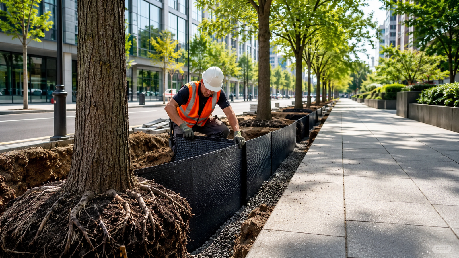
Tree roots usually grow where oxygen, moisture, and loose soil are available. In dense urban areas, that growth can conflict with sidewalks, curbs, retaining edges, irrigation lines, stormwater channels, and underground utilities. A root barrier does not remove root growth. It redirects roots away from structures that need dimensional stability.
For urban construction, root direction control should be planned before tree planting, paving, and utility installation. Retrofitting a barrier after pavement lifting or pipe intrusion usually requires excavation, root cutting, and surface repair, which increases disturbance to both the tree and the built structure.
A practical root barrier layout should define:
- barrier depth according to root behavior and pavement base depth;
- distance from trunk, curb, pavement edge, wall, or utility trench;
- vertical or angled placement depending on redirection target;
- sealed joints where multiple panels are used;
- top-edge height to prevent roots from growing over the barrier;
- inspection points before backfilling and planting.
| Urban Condition | Root Barrier Direction | Design Control |
|---|---|---|
| Street trees beside sidewalks | Redirect roots downward and away from slab edges | Keep barrier continuous along the pavement side |
| Tree pits near curbs | Reduce lateral root contact with curb structure | Protect the upper edge from maintenance damage |
| Landscaped podiums or planters | Separate root zone from waterproofing or drainage layers | Avoid puncture against deck protection layers |
| Parking lots and paved plazas | Control root expansion beneath pavement base | Coordinate with structural fill and compaction plan |
| Utility corridors near planting zones | Redirect roots away from pipes and cables | Seal overlaps and penetrations around service lines |
Barrier depth should be selected with the planting design, not added as a late detail. A shallow barrier may only delay root entry. In many urban tree pit or pavement-edge applications, a depth range of 600 mm to 900 mm is often used as a practical starting point, while deeper systems may be considered for large tree species, narrow planting strips, or infrastructure with low tolerance for root contact.
| Material Option | Suitable Use | Limitation to Check |
|---|---|---|
| HDPE geomembrane | High stiffness and puncture resistance near hard structures | Requires controlled seams and smooth bedding |
| Rigid HDPE root barrier sheet | Vertical root redirection along sidewalks and curbs | Panel joints must stay closed under backfill pressure |
| LLDPE geomembrane | Irregular subgrade or settlement-prone zones | Lower stiffness than HDPE in some designs |
| Geomembrane with geotextile protection | Areas with angular fill or high installation damage potential | Protection layer must remain continuous |
Root direction control also requires soil planning. If the protected root zone is too narrow, compacted, or dry, roots may search for moisture through gaps, edges, and drainage paths. The barrier should be combined with adequate planting soil volume, irrigation planning, and aeration where the landscape design requires long-term tree health.
Installation errors that reduce root direction control include:
- open joints between barrier panels;
- top edge buried too low, allowing roots to pass over;
- barrier installed with gaps around utility penetrations;
- loose backfill that lets the sheet shift;
- cuts made during irrigation or lighting installation;
- sharp folds that create weak zones in the barrier.
Pavement and Utility Line Separation
Urban landscape protection often depends on separation. The root barrier should create a physical boundary between the biological root zone and built elements such as pavement bases, road shoulders, foundations, utility ducts, stormwater pipes, and irrigation controls. This boundary reduces direct contact between roots and structures that require stable alignment.
Pavement damage usually appears as slab lifting, edge cracking, uneven pavers, curb displacement, or surface settlement after roots occupy the base course. Utility damage can occur when roots follow moisture around joints, trenches, pipe bedding, or drainage paths. A barrier system should therefore be aligned with both the landscape plan and the civil utility layout.
| Protected Element | Separation Objective | Barrier Detail |
|---|---|---|
| Concrete sidewalk | Reduce root contact with slab base and joints | Install continuous vertical barrier along pavement edge |
| Asphalt path | Reduce deformation from root expansion under base course | Extend barrier below the compacted base layer |
| Stormwater pipe | Limit root entry toward joints and bedding moisture | Seal barrier around trench interfaces |
| Electrical or communication duct | Maintain access zone without root mass interference | Keep barrier aligned with utility corridor edge |
| Irrigation line | Separate controlled watering from root escape paths | Avoid open cuts around valves and pipe crossings |
For pavement protection, the barrier should normally extend below the pavement base and into stable soil. If the barrier stops at the bottom of the base layer, roots may grow beneath it and return upward near joints or softer subgrade zones. The final depth should reflect pavement thickness, base course depth, tree species, and local soil conditions.
The top of the barrier also needs control. If the upper edge is too low, roots can cross over into the pavement zone. If it is too exposed, landscape tools and maintenance work can damage it. A typical detail may keep the top edge slightly below finished grade while still high enough to reduce root bypass, but the exact position should follow the landscape and civil drawings.
For utility line separation, barrier design should avoid creating a maintenance problem. Utility corridors often require future access, so the barrier should be located where excavation crews can identify it and avoid accidental cutting. As-built records should show barrier alignment, depth, joint locations, and areas near service crossings.
A separation checklist should include:
- Confirm barrier location against utility drawings before excavation.
- Mark service crossings before barrier placement.
- Use smooth bedding beside pipes, ducts, and cable corridors.
- Seal or fit the barrier around unavoidable penetrations.
- Keep seams away from high-stress corners where possible.
- Record final alignment before paving or planting.
- Protect exposed edges during later landscape work.
The barrier should not be treated as a substitute for correct pavement design. Pavement still needs suitable base thickness, compaction control, drainage, edge restraint, and movement tolerance. The barrier reduces root contact, but poor base preparation can still cause settlement or cracking.
Drainage Layer and Soil Compatibility
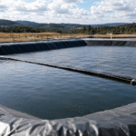
A root barrier changes how water, air, and roots move through soil. If drainage and soil compatibility are not reviewed, the barrier may protect pavement but create poor planting conditions. Urban trees need oxygen, moisture, and enough soil volume. A sealed barrier placed without drainage planning can trap water, dry out one side of the root zone, or force roots toward unsealed paths.
Drainage design should maintain water movement away from pavements and utilities while allowing the planting zone to function. The barrier should not block designed subsoil drainage, underdrains, or engineered soil profiles unless the drawings specify a closed containment detail.
Common drainage and soil issues include:
- water accumulating against an impermeable barrier;
- compacted backfill reducing oxygen in the root zone;
- fine soil migrating into drainage aggregate;
- roots following wet drainage paths around barrier ends;
- barrier edges directing water toward pavement subgrade;
- geotextile clogging when soil gradation is not matched.
A PET non-woven geotextile can support separation and filtration where soil and drainage aggregate meet. It can also protect geomembrane surfaces from puncture. However, geotextile selection should consider soil type, opening size, mass per unit area, drainage requirement, and installation stress. A heavy protection geotextile is not always the same as a filtration geotextile.
| Layer | Function | Check Before Installation |
|---|---|---|
| Planting soil | Supports root growth, moisture storage, and aeration | Avoid over-compaction near the root zone |
| Root barrier | Redirects roots and separates landscape from structures | Keep vertical continuity and sealed joints |
| Geotextile protection layer | Cushions geomembrane from stones and installation damage | Ensure full coverage at high-contact surfaces |
| Filtration geotextile | Separates fine soil from drainage aggregate | Match geotextile opening size with soil gradation |
| Drainage aggregate | Moves water away from the protected zone | Avoid sharp aggregate directly against membrane |
| Underdrain or outlet | Provides controlled water discharge | Confirm slope, outlet condition, and access for maintenance |
Soil compatibility should be checked before backfilling. Highly compacted clay, poorly graded fill, construction debris, and sharp recycled aggregate can reduce both landscape performance and barrier durability. Where possible, the soil beside the root zone should support root health, while the protected structure side should use stable fill that does not puncture or deform the barrier.
A practical review should include:
- soil texture and compaction level near the planting zone;
- drainage path and outlet location;
- presence of angular stones or rubble near the membrane;
- compatibility between geotextile and soil gradation;
- root barrier alignment at drainage interfaces;
- slope direction away from pavements and service lines;
- maintenance access to drains, cleanouts, or inspection points.
| Detail Area | Common Problem | Control Measure |
|---|---|---|
| Barrier end | Roots grow around the open return | Extend or return the barrier as shown in design |
| Drain outlet | Roots follow moisture path | Separate root zone from outlet zone with fitted detailing |
| Soil transition | Fine soil enters drainage aggregate | Use compatible filtration geotextile |
| Gravel contact | Stones press into geomembrane | Add protection geotextile or fine bedding layer |
| Tree pit edge | Water collects against pavement base | Provide slope or drainage outlet |
Final inspection should happen before landscape cover, mulch, paving, or hardscape finishing. The review should confirm barrier continuity, drainage clearance, soil placement, and protection layer coverage. For urban projects with future maintenance needs, the installed barrier line should be photographed or recorded in the as-built package.
Long-term Durability
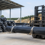
Long-term durability in urban root barrier systems depends on polymer formulation, burial condition, exposure time before cover, soil chemistry, seam stability, and future maintenance access. For HDPE geomembrane-based barriers, specifications may refer to GRI-GM13-type requirements, including carbon black content, dispersion, tensile properties, puncture resistance, stress-crack resistance, and oxidative stability. Exposed storage and exposed top edges should be controlled because UV, heat, and repeated wet-dry cycles can accelerate surface aging. In buried urban applications, durability is usually improved by smooth bedding, stable backfill, limited tensile strain, protected seams, and documented access points for later landscape or utility work.
UV Exposure and Burial Conditions
Root barriers are usually designed for buried service, but they can still face UV exposure during storage, staging, installation, delayed backfilling, and at exposed upper edges. UV exposure is more relevant when rolls are left uncovered on site, panels are installed before planting work is ready, or barrier edges remain visible near pavement, tree pits, retaining edges, or service corridors.
For HDPE geomembrane, carbon black is commonly used as part of the UV stabilization system. A project specification may require carbon black content and dispersion checks, especially when the material may remain exposed during construction. However, UV resistance should not be treated as permission for uncontrolled outdoor storage. Long exposure, high surface temperature, dust, and mechanical handling can still affect the sheet surface and seams.
| Exposure Condition | Durability Concern | Site Control |
|---|---|---|
| Rolls stored outdoors before installation | UV exposure, heat buildup, packaging damage | Keep rolls covered and supported off rough ground |
| Installed barrier left uncovered | Surface aging and construction damage | Backfill or cover after inspection as soon as practical |
| Exposed top edge near finished grade | UV, tools, mowing, edging, foot traffic | Cap, bury, or protect the upper edge |
| Hot pavement or dark hardscape nearby | Higher surface temperature and thermal movement | Allow for expansion and avoid tight restraint |
| Repeated wet-dry cycles at shallow depth | Edge movement and soil shrinkage gaps | Use stable backfill and proper edge detailing |
Burial depth and soil cover should match the landscape design. A root barrier placed too close to the surface can be damaged by planting tools, edging work, irrigation repair, or pavement maintenance. A barrier placed too deep without a continuous upper section may allow roots to pass over the system.
For many urban tree pit and pavement-edge applications, barrier depths around 600 mm to 900 mm are often used as a practical design range, while deeper installations may be needed for larger trees, narrow planting strips, utility corridors, or retaining structures. The final depth should be set by the project specification and site design team.
A durable buried installation should control four points:
- the barrier remains continuous from the designed top elevation to the designed bottom elevation;
- the upper edge reduces root overgrowth without being exposed to frequent tool contact;
- the backfill supports the sheet without sharp stones or voids;
- the barrier is not locked under excessive tensile strain from settlement or hardscape movement.
Thermal expansion also needs attention during installation. HDPE and LLDPE sheets can expand under heat and contract when temperatures drop. If the sheet is installed under high tension during hot conditions, later contraction may increase stress at seams, corners, and fixed edges. If it is installed with uncontrolled wrinkles, folds can become stress points during backfilling.
| Check Item | Acceptable Direction |
|---|---|
| Roll condition | No torn packaging, deep scratches, crushed edges, or contamination |
| Surface exposure | No unnecessary long-term sunlight exposure before burial |
| Top edge | Protected, aligned, and not left as an exposed cutting line |
| Sheet tension | No sharp folds, forced stretching, or unsupported hanging sections |
| Backfill readiness | Fine soil or approved bedding available before cover placement |
| Final cover | Enough soil depth to protect the sheet from routine landscape work |
Burial condition is often more important than the product label. A stable material can lose performance if it is installed over rubble, stretched across voids, cut during irrigation work, or left exposed at the finished grade.
Chemical Resistance in Urban Soil
Urban soil is rarely a clean natural profile. It may contain deicing salts, fertilizers, organic matter, road runoff, hydrocarbons from parking areas, alkaline concrete residue, acidic organic zones, pesticides, construction debris, or contaminated fill. A root barrier must be selected with these conditions in mind, especially near roads, industrial landscapes, service yards, brownfield redevelopment areas, and utility trenches.
HDPE geomembrane is widely used where chemical resistance is required, but the correct approach is still compatibility review. Soil chemistry, temperature, exposure concentration, contact duration, and mechanical stress all affect field performance. A barrier used near hydrocarbon-contaminated soil or industrial runoff should not be selected only by thickness.
| Urban Soil Condition | Possible Effect on Barrier System | Specification Control |
|---|---|---|
| Deicing salt near roads | Salt exposure, wet-dry cycling, soil structure change | Review polymer compatibility and drainage |
| Fertilizer-treated planting soil | Nutrient salts and pH variation | Check soil chemistry and avoid trapped aggressive zones |
| Concrete backfill or rubble | High alkalinity and sharp contact points | Remove debris and use bedding or protection geotextile |
| Hydrocarbon-contaminated soil | Chemical exposure beyond normal landscape use | Require compatibility review before material approval |
| Industrial runoff zones | Mixed chemical exposure | Use project-specific chemical data instead of generic claims |
| Organic wet soil | Microbial activity and low-oxygen conditions | Maintain drainage and avoid stagnant pockets |
Chemical durability is not only about the sheet surface. Seams, patches, penetrations, and exposed edges also need review. If soil chemistry weakens the seam area or if contaminants collect at folds and overlaps, local deterioration may occur before the main sheet shows visible damage.
For HDPE geomembrane-based root barriers, specifications may include:
- polymer type and minimum density where HDPE is required;
- carbon black content and dispersion requirements;
- oxidative induction time testing, such as standard OIT or high-pressure OIT;
- stress-crack resistance testing where sustained strain may occur;
- chemical compatibility review for contaminated soil or runoff exposure;
- seam method and seam inspection procedure;
- protection geotextile where angular fill or rubble cannot be fully avoided.
LLDPE geomembrane may be considered where flexibility is more important, such as irregular subgrade, settlement-prone areas, or complex planter shapes. However, chemical compatibility should still be checked for the actual soil or liquid exposure. Flexibility does not remove the need for compatibility review.
A simple chemical review process should follow this sequence:
- Identify whether the site is normal landscape soil, roadside soil, industrial soil, or remediated fill.
- Review soil test data if contamination is suspected.
- Check pH, hydrocarbons, salts, solvents, or other relevant chemicals.
- Confirm whether the barrier will be in direct contact with the affected soil.
- Select HDPE, LLDPE, or another specified material based on compatibility.
- Add a PET non-woven geotextile protection layer if chemical exposure is combined with puncture exposure.
- Record the approved material and installation limits in the project file.
Where chemical exposure is uncertain, avoid broad claims such as “suitable for all soils.” A better specification states the reviewed exposure condition, the approved material, the required protection layer, and the inspection method before cover placement.
Inspection Access and Maintenance Planning
A buried root barrier becomes difficult to evaluate after landscaping, paving, or utility work is complete. Long-term durability therefore depends on inspection access and maintenance planning before the system is hidden. The project should record where the barrier is located, how deep it is, where seams are placed, and where it crosses drainage or utility zones.
Maintenance problems often occur when later crews do not know a barrier is present. Irrigation repair, lighting installation, pavement saw cutting, trenching, root pruning, or tree replacement can cut through the sheet. Once a cut is hidden under soil, roots may follow the opening and bypass the system.
| Record Item | Purpose |
|---|---|
| Barrier alignment | Helps future crews avoid accidental cutting |
| Installed depth | Shows whether the barrier protects pavement base or utility corridor |
| Seam locations | Supports later inspection and repair planning |
| Material type and thickness | Confirms repair material compatibility |
| Protection geotextile location | Shows where puncture protection was installed |
| Drainage interfaces | Helps identify possible root bypass routes |
| Repair patches | Records areas that need future observation |
Inspection access does not always mean leaving the barrier exposed. In many projects, access means accurate records, marked edges, inspection photos, and clear maintenance notes. In high-use urban landscapes, maintenance teams should know where digging is restricted and what repair method is required if the barrier is damaged.
Pre-cover inspection should be treated as the main quality control point. Before the system is buried, the project team should check:
- no cuts, holes, burn marks, deep scratches, or sharp folds;
- seams are continuous and clean;
- overlaps match the approved detail;
- corners and terminations are closed;
- utility penetrations are fitted without open gaps;
- protection geotextile is continuous where specified;
- drainage outlets are not blocked by the barrier;
- top edge elevation matches the drawing;
- backfill is approved before placement.
For larger geomembrane installations, seam testing may be specified when the welding method allows it. Double-wedge welds may allow air channel testing, while extrusion welds may allow vacuum box testing. Smaller landscape root barrier systems may rely more on visual inspection, overlap control, mechanical fastening checks, and documented repair patches. The method should match the project size, material type, and specification.
Maintenance planning should also address root behavior over time. Roots may grow around barrier ends, over low top edges, through unsealed joints, or along moisture paths near drains. Regular landscape observation should focus on pavement lifting, curb movement, irrigation leaks, soil settlement, exposed barrier edges, and root emergence near barrier termination points.
| Maintenance Item | Review Direction |
|---|---|
| Exposed top edge | Check during routine landscape maintenance |
| Pavement movement | Review when cracks, lifting, or uneven settlement appears |
| Drainage outlet | Check after heavy rainfall or seasonal maintenance |
| Irrigation repairs | Confirm no barrier cuts were made during trenching |
| Tree replacement | Locate and protect the existing barrier before excavation |
| Utility work | Mark barrier alignment before digging |
| Repair area | Reinspect after soil settlement or new planting work |
If damage is found, repair should use compatible material and an approved patch detail. A small slit should not be left open because roots can enter narrow paths over time. The repair area should be cleaned, patched, inspected, and recorded before it is covered again.