Geotextile erosion control is used to stabilize soil surfaces, separate soil from stone layers, filter seepage water, and reduce soil migration under hydraulic loading. In civil engineering, reservoir banks, drainage channels, culvert outlets, stormwater basins, and shoreline protection works, PET continuous filament non-woven geotextile is commonly selected where filtration, separation, puncture resistance, and site installation tolerance must work together. Product selection should not rely on fabric weight alone. Slope angle, soil gradation, runoff intensity, riprap size, overlap layout, anchoring method, and inspection frequency all affect field performance.
Slope Coverage
Slope coverage with PET non-woven geotextile controls surface erosion by holding soil particles in place while allowing water to pass through the fabric. For mild slopes such as 3H:1V, a lighter geotextile may be sufficient when vegetation, soil cover, or aggregate cover is installed quickly. For steeper slopes, concentrated runoff, weak subgrade, or exposed construction periods, higher mass and puncture resistance are usually required, often within 200–600 g/m² depending on soil condition, flow exposure, cover material, and installation stress. Correct overlap direction, full soil contact, and temporary fixing are as necessary as material weight because loose panels can wrinkle, lift, or channel water beneath the slope surface.
Geotextile Weight by Slope Condition
Geotextile weight should be selected according to slope angle, soil erodibility, expected runoff, installation traffic, and cover material. Mass per unit area helps indicate robustness, but filtration behavior, tensile strength, elongation, puncture resistance, and permeability must also match the site condition. In erosion control, PET continuous filament non-woven geotextile works as a separation, filtration, and protection layer. It does not replace slope grading, drainage design, or final surface protection.
| Slope Condition | Engineering Concern | Selection Direction |
|---|---|---|
| Mild slope with stable soil | Light sheet flow and limited soil movement | Lower to medium mass, good permeability, proper overlap |
| Moderate slope with loose soil | Rill erosion, runoff concentration, surface slippage | Medium mass, stronger tensile properties, closer temporary fixing |
| Steep slope or weak subgrade | Fabric movement, soil loss, and higher installation stress | Higher mass, better puncture resistance, reinforced anchoring |
| Slope under aggregate or riprap cover | Angular stone pressure and localized puncture | Higher puncture resistance and adequate thickness |
| Long exposed period before cover | UV exposure, wind uplift, and edge movement | UV-resistant specification, temporary restraint, and shorter exposure window |
A slope coverage specification should define more than fabric weight. It should include mass per unit area, tensile strength, CBR puncture resistance or equivalent puncture value, filtration opening size, water flow capacity, UV exposure limit, roll width, overlap width, and installation direction. For fine-grained soils, filtration compatibility needs review because an opening size that is too large may allow soil migration, while an opening size that is too small may increase clogging risk and pore pressure.
Overlap Direction on Inclined Surfaces
Overlap direction on slopes should follow the water path. The upper sheet should lap over the lower sheet so surface runoff moves across the overlap rather than entering beneath it. If the lower sheet is placed over the upper sheet, water can enter the seam, lift the fabric, remove soil, and form erosion channels below the geotextile.
For many slope coverage works, overlaps are commonly set within 300–600 mm, but final width should follow project drawings, slope angle, soil type, and hydraulic exposure. Steeper slopes, weaker soils, and flow concentration zones normally need wider overlaps, closer fixing, or sewn seams where displacement risk is high.
- Place overlaps in the direction of surface runoff.
- Avoid vertical wrinkles that can guide water downslope.
- Keep overlap areas clean from loose stones, roots, mud, and debris.
- Use temporary pins, sandbags, soil strips, or approved fixing before cover placement.
- Increase overlap width near drainage outlets, slope transitions, and curved areas.
- Avoid placing major overlap lines directly in concentrated flow paths where possible.
Roll layout should be reviewed before deployment. Random roll placement may reduce installation time, but it often creates poor overlap orientation. This can increase water entry beneath the fabric and reduce slope stability during rain events.
Surface Runoff and Soil Contact Control
Geotextile performs best when it stays in direct contact with the prepared soil surface. Poor contact allows water to move beneath the fabric, carrying fine particles downslope and creating hidden erosion. Once channels form below the fabric, the slope may appear covered while soil loss continues underneath.
Subgrade preparation should remove sharp objects, roots, loose debris, abrupt grade changes, and soft pockets. Depressions should be filled and compacted according to the project specification. A geotextile layer cannot correct unstable foundation soil if the subgrade is not prepared before installation.
| Inspection Point | What to Check | Corrective Action |
|---|---|---|
| Subgrade surface | Smooth, compacted, free of sharp debris | Regrade, compact, or remove obstruction |
| Fabric contact | No bridging, large wrinkles, or voids | Reposition fabric and refix |
| Overlap direction | Upper panel overlaps lower panel | Re-lap before covering |
| Temporary fixing | Panels secured before wind or runoff | Add fixing points where movement is visible |
| Runoff control | No concentrated flow under fabric | Redirect flow or add drainage protection |
| Damage review | Tears, punctures, displaced overlaps, UV exposure | Patch, replace, or cover promptly |
Runoff should not discharge directly onto an uncovered geotextile slope from pipes, road edges, or temporary drainage channels. Where concentrated discharge exists, the design may need a lined channel, check structure, riprap apron, or another energy-control detail.
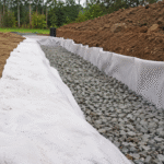
Riprap Underlayment
Riprap underlayment uses PET non-woven geotextile as a separation and filtration layer between angular stone and the prepared subgrade. In slope channels, reservoir banks, culvert outlets, drainage ditches, and shoreline protection works, riprap may range from small graded stone to large armor rock, with D50 sizes from about 100 mm to more than 600 mm depending on hydraulic loading. The geotextile must prevent soil migration, reduce subgrade pumping, and tolerate installation stress from stone placement. Selection should consider mass per unit area, CBR puncture resistance, tensile strength, apparent opening size, permittivity, overlap width, and drop height during rock placement.
Separation Between Stone and Subgrade
Riprap placed directly on soil can press angular stone into the subgrade and allow fine particles to migrate upward into rock voids. Over time, this can reduce drainage capacity, cause settlement, and create uneven riprap coverage. A PET non-woven geotextile underlayment provides a continuous separation layer so the stone layer remains open while the soil base stays in place.
| Site Condition | Risk Without Geotextile | Underlayment Requirement |
|---|---|---|
| Fine sandy subgrade | Soil migration into rock voids | Stable filtration and sufficient overlap |
| Silty or erodible soil | Pumping and washout under flow | Suitable AOS and water flow capacity |
| Soft slope surface | Local settlement under stone | Higher mass and careful subgrade preparation |
| Channel bend or outlet | Turbulence and concentrated flow | Secure edge treatment and stone confinement |
| Large angular riprap | Puncture during placement | Higher puncture resistance and controlled drop height |
The underlayment should be installed on a trimmed and compacted surface. It should not be placed over soft pockets, loose fill, standing water, roots, or sharp debris. If the subgrade is unstable before installation, the geotextile will not correct the foundation problem.
- Grade the slope or channel bed to the design line.
- Remove sharp stones, roots, construction waste, and loose clods.
- Compact or proof-roll the subgrade where specified.
- Place geotextile without dragging it across rough ground.
- Keep panels flat with limited wrinkles and continuous soil contact.
- Place riprap from the toe upward on slopes to reduce fabric displacement.
Puncture Resistance Under Angular Rock
Angular riprap creates localized pressure on the geotextile during placement and service. The risk increases with large stone size, sharp edges, steep slopes, greater drop height, and equipment movement over placed rock. For this reason, puncture resistance is often more relevant than fabric weight alone.
PET continuous filament non-woven geotextile is commonly selected where underlayment must absorb irregular contact stress. Its thickness, elongation, and multidirectional fiber distribution help reduce damage from stone contact. Fabric damage can still occur if large rock is dropped from excessive height or if equipment turns directly on thin stone cover.
| Riprap Condition | Installation Stress | Geotextile Direction |
|---|---|---|
| Small rounded stone | Lower puncture risk | Medium non-woven geotextile may be sufficient |
| Angular graded stone | Moderate point loading | Higher puncture resistance and controlled placement |
| Large armor rock | High localized stress | Heavy non-woven geotextile or cushioning layer |
| Steep slope placement | Sliding and drag stress | Stronger tensile properties and toe restraint |
| Equipment-assisted placement | Rutting and turning risk | Minimum stone cover before traffic access |
Field control matters as much as product selection. Large rock should not be dropped directly onto exposed geotextile from high elevation. Where large riprap is used, the first stone layer should be placed carefully to form a protective bedding zone. Equipment should not drive on exposed geotextile, and traffic over thin stone cover should be restricted.
- Check for tears caused by stone edges.
- Check for holes caused by rock impact.
- Confirm the fabric has not displaced downslope.
- Confirm no subgrade is exposed between panels.
- Remove major wrinkles before heavy stone placement.
- Patch damaged sections with the same or stronger geotextile.
Filter Opening Size for Soil Retention
A riprap underlayment must allow water to pass while retaining soil particles. If the geotextile opening size is too large, fine soil can migrate through the fabric and into the riprap voids. If the opening size is too small, the fabric may clog, reduce drainage, and increase pore pressure behind the slope or channel lining.
Apparent Opening Size is commonly referenced through ASTM D4751, while water flow capacity may be reviewed through permittivity or flow rate testing such as ASTM D4491. These values should be checked against soil gradation, hydraulic condition, and expected sediment load.
| Design Factor | Why It Matters | Review Direction |
|---|---|---|
| Soil grain size distribution | Determines soil retention requirement | Match AOS to fine soil content and gradation |
| Silt and clay content | Affects clogging risk | Review permeability and clogging sensitivity |
| Flow direction | Controls water movement through fabric | Confirm the filtration path below riprap |
| Hydraulic gradient | Higher gradient increases migration risk | Use conservative filtration design |
| Sediment load | May block the fabric surface | Provide surface protection and maintenance access |
The geotextile should not be treated as a waterproof layer. Its function is filtration and separation. Water must pass through the underlayment without carrying soil out of the slope or channel bed. This is especially relevant at culvert outlets, spillways, detention basin inlets, drainage channels, reservoir embankments, and stormwater discharge points.
Edge Anchoring
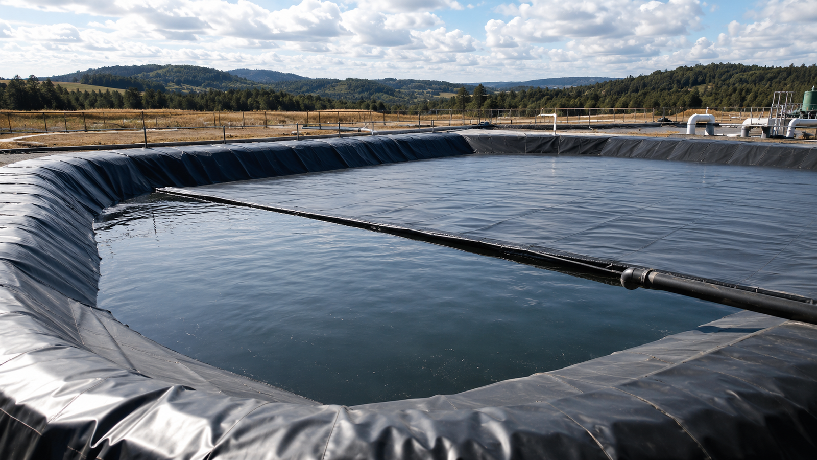
Edge anchoring keeps geotextile erosion control layers fixed against wind, runoff, slope movement, and stone placement stress. On exposed slopes, drainage channels, reservoir banks, and stormwater outlets, unsecured edges can lift within hours under wind or concentrated flow, allowing water to enter beneath the fabric and remove subgrade soil. Anchor trenches are commonly placed at the crest and side boundaries, with typical dimensions ranging from 300–600 mm deep and 300–600 mm wide depending on slope height, soil strength, hydraulic load, and cover material. Toe fixing at the slope bottom prevents downslope sliding, while edge protection controls underflow, overlap opening, and fabric displacement during service.
Anchor Trench Size and Placement
Anchor trenches lock the geotextile into stable ground before the fabric runs down a slope or across a channel lining. The trench should be positioned outside the active erosion zone, usually at the slope crest, side edges, or transition areas where flow could enter beneath the geotextile.
| Site Condition | Anchoring Concern | Design Direction |
|---|---|---|
| Short mild slope | Limited fabric tension | Smaller trench may be acceptable if soil is firm |
| Long slope face | Higher fabric drag and runoff exposure | Deeper trench and closer edge fixing |
| Loose sandy soil | Pullout risk | Wider trench and well-compacted backfill |
| Channel or spillway edge | Flow entry under fabric | Trench outside the main flow path |
| Exposed installation period | Wind uplift before cover | Temporary weights plus trench anchoring |
- Excavate the trench to the specified width and depth before deployment.
- Place the geotextile into the trench without tearing, folding, or excessive tension.
- Extend enough fabric into the trench to allow full backfill contact.
- Backfill with approved soil or aggregate, not construction waste or sharp debris.
- Compact trench backfill in layers where specified.
- Keep the trench line continuous at corners, slope breaks, and side transitions.
For PET non-woven geotextile, anchoring should not rely only on pins or surface weights where the slope is exposed to stormwater or wind. Pins may provide temporary positioning, but they do not provide the same restraint as a properly backfilled trench.
Toe Fixing at Slope Bottom
Toe fixing controls the lower end of the geotextile where gravity, runoff, and cover material can pull the fabric downslope. The slope bottom is also where water velocity may increase, sediment may collect, and riprap or soil cover may shift during heavy rainfall. If the toe is not secured, the geotextile can slide, wrinkle, fold, or expose the subgrade.
| Toe Condition | Main Risk | Fixing Direction |
|---|---|---|
| Vegetated slope bottom | Fabric exposure and soil washout | Buried toe with compacted soil cover |
| Riprap-covered slope | Fabric pullout during stone placement | Toe trench plus stone confinement |
| Drainage ditch transition | Flow entry under geotextile | Overlap into channel lining or protected cutoff |
| Reservoir bank | Wave action and water level change | Buried toe below erosion exposure zone |
| Culvert outlet slope | Turbulence and scour | Toe apron, riprap lock, or lined transition |
Toe fixing should be completed before heavy cover placement creates fabric movement. On slopes receiving riprap, placement should generally start at the toe and proceed upward. This helps lock the lower edge and reduces the chance of dragging the fabric downslope.
- Confirm the toe line follows the design elevation.
- Remove loose soil, mud, and standing water before burial.
- Avoid placing the geotextile over sharp grade breaks without support.
- Keep the fabric in full contact with the subgrade at the toe.
- Secure overlaps before placing riprap or soil cover.
- Prevent machinery from pulling or stretching exposed fabric.
Wind Uplift and Flow Edge Protection
Wind uplift and flow entry are common causes of edge failure during geotextile erosion control installation. Non-woven geotextile has an open and flexible structure, which supports filtration and soil contact, but exposed panels can move if edges are not secured. Wind can lift fabric, create wrinkles, open overlaps, and expose subgrade before final cover is placed.
| Exposure Type | Failure Mode | Control Measure |
|---|---|---|
| Wind before cover | Panel lifting and overlap opening | Temporary ballast, pins, trench anchoring |
| Sheet runoff | Water entry at upper edge | Crest trench and drainage diversion |
| Concentrated flow | Subgrade washout under fabric | Protected inlet, cutoff trench, riprap apron |
| Side flow | Edge peeling and soil loss | Side trench and overlap extension |
| Construction delay | UV exposure and fabric movement | Shorter exposure period and inspection after weather |
Temporary controls should be installed immediately after roll deployment, especially on large exposed areas. Sandbags, approved pins, soil cover strips, or staged backfilling can reduce movement before final cover is placed. These measures should not replace permanent anchoring where the design requires trenches, buried edges, or structural transitions.
- Check wind forecast before deploying large panels.
- Do not leave loose roll ends exposed overnight where strong wind is expected.
- Inspect crest, side, and toe edges after rainfall.
- Look for lifted corners, open overlaps, tears, and soil tracks.
- Repair displaced panels before placing permanent cover.
- Confirm drainage is diverted away from uncovered geotextile edges.
Edge protection should be coordinated with drainage design. If stormwater from roads, pads, or construction areas discharges directly onto an exposed geotextile edge, anchoring alone may not be enough. The site may need berms, diversion channels, check structures, riprap aprons, or lined flow paths to prevent underflow.