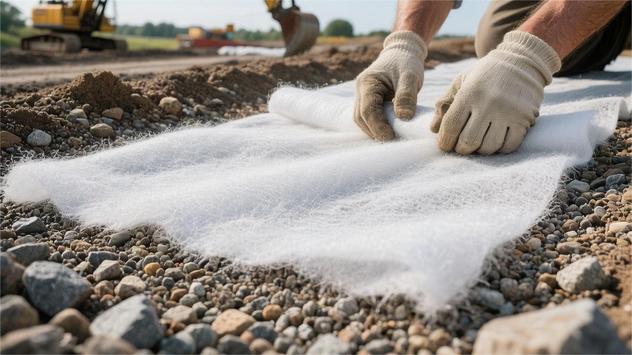
Non-woven geotextile resembles felt and has excellent water permeability; its primary uses are filtration, separation, and protection.
In subsurface drainage (such as French drains), it provides a water flow rate of up to 100 gallons per minute while providing 100% silt interception to prevent pipe clogging. In road construction, laying it between gravel and soft soil effectively prevents subgrade mixing and settlement.
This material is mostly made of high-strength polypropylene (commonly in 4-8 oz/sq yd specifications). It is corrosion-resistant and extremely difficult to degrade, with an underground burial life typically exceeding 50 years, making it an essential, cost-effective material for modern civil engineering and yard landscape drainage.
French Drains and Trench Drains
When installing French Drains and Trench Drains, 3.5 to 4.0 oz/sq yd polypropylene non-woven geotextile is typically used to wrap the gravel and perforated pipe. This material achieves a water flow rate of 100-120 gallons/minute/square foot and can block silt and clay particles larger than 0.15 mm. Once wrapped with geotextile, the system’s maintenance-free period typically reaches 15 to 20 years, physically isolating the soil and preventing groundwater from carrying silt that would clog the 4-inch PVC drainage pipes.
Material Parameters
According to the American Association of State Highway and Transportation Officials (AASHTO) M288 specification, subsurface French drains must have physical layer calibrations based on soil particle size distribution. The weight of polypropylene non-woven geotextile fluctuates between 3.0 and 8.0 oz/sq yd, with thicknesses corresponding to 40 to 90 mils. Lightweight 3.5 oz material is suitable for shallow surface trenches, while heavy-duty 6.0 oz material should be selected for deep collector trenches over 6 feet deep.
Thickness and weight together determine the Apparent Opening Size (AOS), which is tested according to the ASTM D4751 standard. The AOS value represents the maximum particle diameter the fabric can block, calibrated using US Standard Sieve numbers. A higher sieve number corresponds to a smaller physical pore diameter; heavy clay environments require non-woven fabric with an AOS of 100 (pore size 0.15 mm).
When the surrounding soil is ML-grade soil containing more than 50% silt, the pore size selection must balance water permeability and sand blockage. A 4.0 oz needle-punched fabric set at AOS 70 sieve (0.212 mm) provides an excellent filtration balance. Fine particles gradually accumulate on the outside of the fabric, forming a natural soil bridging filter zone outside the trench.
- Water flow carries mixed particles of 0.1 mm to 0.3 mm toward the drainage ditch.
- Coarse particles larger than 0.212 mm are blocked on the surface of the non-woven fabric.
- Fine silt of 0.1 mm then accumulates behind the coarse particles.
- The inner side of the native soil extends 1 to 2 inches outward to form a natural graded filter layer.
Once the natural filter layer is formed, the Water Flow Rate of the material itself becomes the parameter for maintaining the discharge pressure of the trench. Under the ASTM D4491 test specification, 4.0 oz non-woven fabric can maintain a vertical penetration of 120 gallons per minute (GPM) per square foot. The groundwater infiltration rate in North American coarse sand environments is approximately 10 inches/hour; the 120 GPM design capacity leaves a significant margin for flood drainage.
| Regional Soil Class (USCS) | Recommended Non-Woven Parameters | Min Tensile Strength (lbs) | Water Flow Rate (gpm/ft²) | Apparent Opening Size (AOS) |
|---|---|---|---|---|
| Gravel/Coarse Sand (GW/SP) | 3.0 oz – 3.5 oz | 90 – 100 | 135 – 150 | #50 (0.300 mm) |
| Silt/Loam (ML/SM) | 4.0 oz – 4.5 oz | 100 – 120 | 110 – 120 | #70 (0.212 mm) |
| Fine Clay (CL/CH) | 6.0 oz | 160 | 70 – 75 | #100 (0.150 mm) |
| Mixed Backfill/Silt | 8.0 oz | 205 | 90 | #80 (0.180 mm) |
After the flow velocity parameters meet the standards, the material’s resistance to damage during aggregate dumping must be evaluated. The ASTM D4632 test item is used to determine the Grab Tensile Strength of the material. The tensile strength of 3.5 oz non-woven fabric is around 90 lbs, while 6.0 oz industrial-grade fabric can withstand a tensile break limit of 160 lbs.
Tensile strength deals with various instantaneous physical loads generated by backfilling operations. Mechanical operations at the construction site and the physical characteristics of the aggregate will cause different levels of puncture pressure on the geotextile.
- 1/2 to 3/4 inch granite gravel has many sharp angular edges.
- A Skid Steer dumps 0.5 cubic yards of aggregate at once.
- Gravitational acceleration acts on the bottom of deep trenches exceeding 36 inches.
Testing CBR puncture strength according to the ASTM D6241 standard, 4.0 oz material withstands a concentrated penetration force of 250 lbs. When the construction environment meets the high-load conditions mentioned above, an upgrade to 6.0 oz thick fabric with a CBR puncture strength of 410 lbs is mandatory. The long-term stability of physical strength is further strictly constrained by the polymer’s chemical composition.
Non-woven fabrics made of Virgin Polypropylene have excellent resistance to acids and alkalis. In soil cross-sections with a pH range between 3 and 12, the physical degradation rate of polypropylene fibers buried for 20 years remains below 2%. North American municipal construction mandates the use of only 100% continuous extruded polypropylene filament needle-punched geotextiles.
Recycled polyester fiber materials undergo irreversible hydrolysis reactions in alkaline soils with a pH higher than 8.0. In some North American states with abundant limestone strata, the groundwater pH often reaches 8.5 or higher. Polypropylene materials are completely immune to chemical erosion in high-alkaline groundwater environments.
The duration of light exposure during surface construction affects the material’s ultraviolet (UV) resistance parameters. The ASTM D4355 specification requires geotextiles to undergo 500 hours of continuous xenon arc lamp irradiation in a test chamber. Qualified materials must retain more than 70% of their original tensile strength to ensure performance does not attenuate during a 14-day construction period.
If a French drain passes through areas with heavy vehicle traffic, the AASHTO M288 specification requires the selection of Class 2 geosynthetic materials. The Elongation of the roll must be greater than 50%. High elongation allows the geotextile to undergo deep physical deformation with the base soil when subjected to a 5000 lbs static wheel crushing load.
For Trench Drains installed at driveway edges, surface runoff often contains car motor oil and winter road de-icing salts. The Trapezoidal Tear Strength of the non-woven geotextile must exceed 40 lbs. The dense polymer network prevents the bristles of mechanical sweeping equipment from causing tear damage to the material edges.
Installation Process
When excavating trenches for French drains, physical dimensions must refer to drainage calculations. A standard North American residential flood prevention system will excavate a trench 18 to 24 inches deep and 10 to 12 inches wide. The bottom of the trench is set with a 1% to 1.5% slope using a laser level, ensuring a 1-inch drop for every 10 feet (approx. 3 meters) of extension.
Clear tree roots and sharp stones from the bottom of the trench. Unroll the 4.0 oz non-woven geotextile along the trench, pressing the material into the bottom and sides. The U-shaped seam area faces the soil side, while the inner side provides a smooth surface to contact the gravel. The fabric should have at least 12 inches (approx. 30 cm) of extra edge pre-reserved above both sides of the trench.
Long-distance drainage ditches often splice multiple sections of non-woven fabric. When laying multiple rolls of material, follow the reverse water flow overlap rule. The downstream fabric is pressed under the upstream fabric, with an overlap of no less than 18 inches. Maintain the continuity of the Apparent Opening Size (AOS) under the ASTM D4751 test standard.
- Seams are sealed using two rows of double-sided butyl tape.
- The width of industrial tape should reach 2 to 3 inches.
- In windy weather, use 6-inch long U-shaped landscape staples to fix the edges every 3 feet.
- Fabric at corners is cut at a 45-degree angle and overlapped by 24 inches.
After the fabric is fixed, dump the first layer of aggregate into the bottom of the trench. Use washed river stone or granite gravel sized between 1/2 and 3/4 inches. Lay it to a thickness of 2 to 3 inches and use a hand compactor to level the gravel surface, maintaining the preset 1% slope. Unwashed gravel has dust on its surface, which forms mud when encountering rain, clogging the micropores of the geotextile.
Place 4-inch diameter perforated PVC pipe (SDR-35 or ASTM D2729 specification) in the center of the gravel bedding. The holes in the pipe are placed facing down, arranged in the 4 o’clock and 8 o’clock directions. Water seeps into the pipe from the bottom, and air circulates from the top. When using corrugated pipe, ensure the pipe runs straight within the trench to avoid recessed blind spots.
Dump the same washed gravel along the sides and top of the pipe. The gravel covering the top should reach 3 to 4 inches thick until only about 4 to 5 inches of depth remains from the surface. Avoid using tracked heavy machinery to crush the polypropylene material at the trench edges during operation.
- Reserve at least 3 inches of gravel space on both sides of the 4-inch pipe.
- Aggregate porosity reaches the 35% to 40% standard.
- Prohibit the use of mixed-graded aggregates such as CR-6 containing limestone powder.
- Total gravel weight calculation is prepared at 0.5 cubic yards per 10 feet.
- Lateral displacement of the pipe during backfilling must not exceed 1/2 inch.
Fold the reserved geotextile edges over the top gravel layer like folding an envelope. The left side fabric is laid flat on the gravel, followed immediately by the right side fabric covering the top. The width of the top overlap reaches 8 to 12 inches, forming a completely enclosed physical filtration barrier, commonly known in the industry as the “burrito” wrap method.
The overlap area is fixed with landscape staples every 2 feet to prevent displacement when backfilling soil. If the construction environment is in a rainy zone, complete the backfilling operation within 14 days after laying the non-woven fabric. Long-term exposure of 4.0 oz polypropylene material to strong sunlight will cause its tensile strength (Grab Tensile typically 100 lbs) to drop significantly due to UV degradation.
Fill 3 to 4 inches of standard topsoil over the enclosed geotextile. The topsoil should be slightly higher than the surrounding lawn surface by about half an inch to allow for natural soil settlement. Then sow tall fescue grass seeds or lay sod. Roots growing in the topsoil will be blocked upon reaching the geotextile surface and will not penetrate the fibers to damage the internal structure.
Trench Drains are mostly used for driveways and hard pavement edges. Excavation depth is determined by the height of the prefabricated trench modules, with the bottom deepened by 4 to 6 inches to lay a compacted sand bed. Use 3.5 oz non-woven geotextile laid flat on the soil surface to wrap the entire foundation pit, isolating the surrounding clay from the drainage base at the bottom.
Place modules made of polymer concrete or high-density polyethylene (HDPE). Each module is about 3.28 feet (1 meter) long and connected through interlocking clips. In the gaps reserved on both sides of the module, drive in a #4 specification rebar every 2 feet for fixation. The non-woven fabric continues to provide soil filtration functionality beneath the hardened base.
When the native soil is heavy clay with an infiltration rate lower than 0.1 inches/hour, the drainage network needs to be connected to a Dry Well. Lay heavy-weight 6.0 oz non-woven geotextile around the sides and bottom of the dry well. Polyester fiber material maintains a flow rate of 120 GPM under soil hydrostatic pressure at a depth of 10 feet underground.
- Inject 150 gallons of clear water into the upstream catch basin for flow testing.
- Observe continuous water flow at the outlet within 45 seconds.
- Install a Pop-up emitter at the end of the network, at least 10 feet from the wall foundation.
- Apply light rolling to the surface after sod is laid, with roller weight not exceeding 200 lbs.
Retaining Walls
In retaining wall engineering, non-woven geotextile is wrapped around the drainage gravel (usually 3/4-inch clean stone) behind the wall as a physical filtration layer. According to the US AASHTO M288 specification, polypropylene needle-punched non-woven fabric with a unit weight of 4 oz/yd² to 6 oz/yd² is typically selected.
This material provides a permeability of 110 to 140 gallons/minute/square foot (gpm/ft²), allowing groundwater to quickly enter the bottom perforated drainage pipe (such as 4-inch ADS corrugated pipe). Its Apparent Opening Size (AOS) is controlled at US Standard Sieve #70 (0.212 mm), intercepting fine particles in the backfill soil and preventing drainage aggregate from silting up and causing hydrostatic pressure overload on the wall.
Selection Reference
State Departments of Transportation (DOT) in the US, when approving physical drainage layers for retaining walls, set the AASHTO M288 specification as the baseline physical parameter threshold. The mass per unit area of polypropylene staple fiber needle-punched non-woven fabric is based on the ASTM D5261 test standard, with values controlled within the range of 4.0 to 8.0 oz/yd².
Under the ASTM D5199 test environment, applying a vertical pressure of 2 kPa, the nominal thickness of 6.0 oz/yd² class material is recorded at 80 to 90 mils (approx. 2.0 to 2.3 mm). Thickness data forms the basis for the material to maintain physical space under gravel compression.
Thickness parameters are physically bound to the material’s mechanical tensile performance. According to the ASTM D4632 Grab Tensile Strength test, using clamps to stretch at a speed of 12 inches/minute, the material’s Machine Direction (MD) and Cross Direction (CD) breaking force both reach 160 lbs.
The breaking elongation index during the stretching process is set to be greater than or equal to 50%. High elongation allows the geotextile to undergo up to 50% local physical extension when wrapping 1.5-inch angular gravel and bearing the weight of the upper fill, avoiding the breakage of the fiber network structure.
When encountering irregular trench edges or buried objects, Trapezoidal Tear Strength becomes a quantitative indicator of the material’s damage resistance. Based on the ASTM D4533 specification, the tear strength threshold for materials used in medium-sized retaining wall projects is controlled between 60 and 85 lbs.
Puncture resistance is evaluated quantitatively through ASTM D6241 (CBR Puncture Test). A flat-head steel probe with a diameter of 50 mm is pressed vertically into a suspended geotextile sample at a speed of 50 mm/minute; the vertical force recorded at the moment the probe penetrates the material must be greater than 410 lbs.
The Federal Highway Administration (FHWA) integrates test data into the Survivability Class parameter system specified by AASHTO M288, based on the mechanical stress levels of the construction environment:
| Physical Performance Index (Based on ASTM tests) | Survivability Class 3 (Normal Backfill) | Survivability Class 2 (Rough Gravel Backfill) |
|---|---|---|
| Grab Tensile Strength (D4632) | 120 lbs (533 N) | 160 lbs (711 N) |
| Elongation at Break (D4632) | ≥ 50% | ≥ 50% |
| Trapezoidal Tear Strength (D4533) | 50 lbs (222 N) | 60 lbs (267 N) |
| CBR Puncture Strength (D6241) | 310 lbs (1378 N) | 410 lbs (1822 N) |
Once the physical barrier is established, the Apparent Opening Size (AOS) is screened by dry sieve testing according to the ASTM D4751 standard. The test uses glass beads of different diameters to pass through the geotextile, calculating the physical pore size at which 95% of the glass beads are intercepted.
- For soil environments with a silt proportion between 15% and 50%, the AOS parameter is required to reach US Standard Sieve #70 (0.212 mm).
- When the proportion of clay particles (fineness less than 0.075 mm) in the backfill exceeds 50%, the AOS index is adjusted to US Standard Sieve #100 (0.150 mm).
- For non-cohesive sandy soil environments (fine particle proportion less than 15%), the AOS is relaxed to Standard Sieve #40 (0.425 mm).
Under the condition of establishing a pore size range of 0.150 to 0.425 mm, the material must provide ample water passage channels. The ASTM D4491 test specification requires that under a constant head pressure of 50 mm, the Permittivity of the material remains at 1.5 to 1.7 sec⁻¹.
Converted into a water flow coefficient, 110 to 135 gallons of water must be allowed to pass through per minute per square foot of material surface. This value aims to handle instantaneous subsurface runoff water pressure generated under a 50-year storm event.
2% to 3% carbon black powder is mixed into the polypropylene resin raw material as a carbon inhibitor. According to the ASTM D4355 test, samples are placed in a xenon arc lamp aging chamber to simulate solar radiation; after 500 hours of continuous irradiation, the physical indicators of the material retain more than 70% of their initial factory values.
Once buried underground, polypropylene fibers provide an extremely wide acid and alkali tolerance range from pH 2.0 to 13.0. In trench environments contacting limestone backfill materials (pH often between 8.5 and 9.5) for 360 consecutive days of immersion, the tensile strength attenuation rate is controlled below 5%.
Microbial resistance is verified through the ASTM D3083 test. A 12-inch by 12-inch sample is buried and incubated for 90 days in active compost soil rich in actinomycetes and fungi; the weight loss rate after removal is set at 0%.
Engineering procurement and on-site installation also need to refer to the physical specifications of rolled materials.
| Factory Specifications of Roll | Common Physical Parameter Values | Construction Application Notes |
|---|---|---|
| Roll Width | 12.5 ft or 15.0 ft (3.8m / 4.5m) | Fits foundation pit widths excavated by medium excavators |
| Roll Length | 360 ft (109.7m) | Reduces longitudinal seams, meets continuous laying needs |
| Area per Roll | 500 sq. yds (418 m²) | Convenient for quantity calculation and stock management |
| Roll Weight | 150 lbs – 200 lbs (68 – 90 kg) | Allows manual lifting operations by two personnel |
The outer layer of rolled materials is wrapped with a 4 to 6 mil thick black opaque polyethylene plastic film. The encapsulation film prevents ultraviolet light with wavelengths of 290 to 400 nanometers from penetrating, protecting the inner fibers from photo-oxidative degradation for up to 6 months during transport and storage at the job site.
The surface temperature of the storage area is limited to below 140 degrees Fahrenheit (60 degrees Celsius). Temperatures above a specific threshold will promote micro-scale thermal contraction of polypropylene fibers, changing the factory-set 0.212 mm Apparent Opening Size parameter.
Installation Indicators
When excavating drainage trenches behind retaining walls, the native soil at the bottom must reach 95% Standard Proctor density (ASTM D698 test specification). The trench bottom is required to maintain a physical slope of at least 1% toward the drainage outlet. Construction personnel must remove all sharp rocks and root fragments larger than 1 inch from the contact surface.
Physical tolerance for flatness is controlled to not exceed a 0.5-inch vertical drop within any 10-foot (approx. 3-meter) length.
Unroll the geotextile along the wall at the bottom of the trench; the contact rate between the material surface and the soil must reach over 90% to prevent suspended or wrinkled areas.
Use U-shaped steel fixing pins (typically 6 or 8 inches long, using 11-gauge wire) to anchor the material onto the soil slope. On inclined backfill surfaces with a slope of 3:1, the pin spacing is set to one every 3 feet (0.9 meters). Pin spacing for the flat bottom is relaxed to one every 5 feet (1.5 meters).
When splicing two adjacent rolls, the overlap width is determined by the California Bearing Ratio (CBR) value of the on-site soil. When the CBR value is greater than 3, adjacent fabric edges physically overlap by 12 to 18 inches. When the CBR value is between 1 and 3, the overlap width increases accordingly to 24 to 36 inches.
Weak soil layers (CBR less than 1) require material overlaps of more than 36 inches or physical sewing using industrial sewing machines. Sewing uses high-strength UV-resistant polyester thread, employing a Double-thread Lockstitch, with a parallel spacing of 0.5 inches between the two rows of stitches.
After laying the geotextile, use loading machinery to pour in clean 3/4-inch to 1.5-inch angular gravel aggregate. To prevent physical drop impact from tearing 4 oz/yd² to 6 oz/yd² class fabric, the aggregate release height from the mechanical bucket is limited to below 3 feet (0.9 meters).
In low-temperature environments (below 32 degrees Fahrenheit/0 degrees Celsius), the breaking elongation of polypropylene material undergoes physical changes; the dumping height of aggregate must be further limited to within 1.5 feet (0.45 meters).
At the top of the C-wrap structure, the folded-over part of the geotextile wrapping the gravel must reach a coverage width of 12 inches. Backfill at least 6 inches of low-permeability topsoil over the folded layer.
A 4-inch PVC perforated drainage pipe (such as SDR 35 specification pipe) is placed in the gravel bedding above the geotextile, with the bottom of the pipe maintaining at least 2 inches of gravel gap from the geotextile at the bottom of the trench. The inlet holes of the perforated pipe are placed facing down (oriented at 4 and 8 o’clock).
In some independent projects, geotextile is used to wrap the drainage pipe separately; the longitudinal overlap seam during wrapping is set directly above the pipe, with an overlap amount of no less than 20% of the pipe’s outer circumference.
The upper limit for polypropylene non-woven fabric exposure to natural sunlight is 14 days. Beyond the 14-day exposure window, UV irradiation causes polymer chain degradation, and the material’s grab tensile strength drops by more than 30% (based on ASTM D4355 standard testing). Aggregate coverage must be completed within two weeks after the material is unpacked and laid.
The compaction of backfill gravel is operated separately in two physical zones.
- Within 3 feet (0.9 meters) of the back of the retaining wall: Limited to using hand-held Vibratory Plate Compactors with an operating weight not exceeding 250 lbs, with a single-layer compaction thickness limited to 6 to 8 inches.
- Beyond 3 feet from the back of the retaining wall: Use 1-ton to 3-ton ride-on single-drum vibratory rollers, with single-layer compaction thickness relaxed to 10 to 12 inches.
When compaction equipment is working above the geotextile, the material surface must already be covered with at least a 6-inch thick layer of gravel. Any heavy machinery with tracks or steel wheels is strictly prohibited from turning or braking on the exposed geotextile surface; instantaneous shear force generated by tracks will break through the material’s 100-160 lbs tensile strength threshold.
According to the FHWA construction manual, a physical cycle of backfilling and compaction is performed for every 2-foot increase in wall construction height.
For soil environments containing a large amount of fine silt (particles passing through a #200 standard sieve exceeding 50%), the roughness coefficient of the contact surface between the geotextile and native soil must be maintained above 0.8. Contractors will spray a small amount of water on the soil slope to bring the soil moisture content within ±2% of the Optimum Moisture Content (OMC), increasing friction to prevent the material from sliding down.
When encountering 90-degree internal or external corner wall structures, the material is not allowed to be excessively mechanically stretched. Construction specifications require reserving an extra 15% pleat length at corner areas to accommodate physical displacement caused by subsequent backfill soil settlement. The number of overlapping seams at a single wall corner should not exceed two.
Asphalt Overlays and Driveways
In asphalt overlay and driveway projects, 4.0 to 8.0 oz/sq yd non-woven geotextile is typically used. Contractors spray 0.20 to 0.25 gallons/sq yd of asphalt Tack Coat on the old pavement. After absorbing the hot asphalt, the material forms a waterproof membrane, delaying the appearance of reflective cracks on the old pavement by 2 to 3 years.
In residential or commercial driveways, it is laid on soft soil subgrades with a CBR (California Bearing Ratio) below 3% to isolate clay from the 6 to 8-inch thick gravel aggregate above, preventing vehicles from crushing gravel into the mud.
Asphalt Overlays
State DOT specifications require pre-treatment of old pavement cracks with widths exceeding 3/8 inch. Construction teams use heavy milling machines to cut off the top 1.5 to 2 inches of oxidized, aged asphalt layer and clean debris from within the gaps with 120 psi high-pressure compressed air. Cracks wider than 0.25 inches must be filled with hot-melt rubberized asphalt sealant heated to 350°F. After industrial sweepers remove surface debris, dust residue on the pavement surface must be strictly controlled below 0.01 lbs/sq yd.
| Old Pavement Pre-treatment Items | FHWA Quantitative Indicators | Physical Treatment Purpose |
|---|---|---|
| Milling Depth | 1.5 – 2.0 inches | Remove aged surface oxidation layer |
| Crack Repair Threshold | > 0.25 inch width | Prevent sealant from sinking or loss |
| Surface Cleanliness | < 0.01 lbs/sq yd dust | Ensure tack coat adheres fully to original pavement |
| Ambient Construction Temp | > 50°F (10°C) | Prevent liquid materials from cooling/solidifying too early |
On the cleaned asphalt surface, asphalt distributors spray PG 64-22 grade undiluted hot asphalt Tack Coat at a rate of 0.22 to 0.28 gallons/sq yd. Mechanical spray temperature is controlled within the 290°F to 325°F range. The spray width of liquid asphalt is 2 to 4 inches wider than the non-woven geotextile to be laid. Spraying operations must be suspended when ambient air temperature is below 50°F or pavement moisture exceeds specified limits.
Specialized paving tractors pull mechanical spindles loaded with 4.0 to 5.0 oz/sq yd non-woven polypropylene geotextile, moving forward at a steady speed of 15 to 20 feet per minute. The equipment applies a constant tension of 5 to 10 lbs/linear inch via tension rollers.
- Paver tracks align with the white line, with error within 2 inches
- Geotextile is laid flat on the not-yet-cooled hot tack coat
- Heavy broom trailers follow immediately, applying 200 lbs of downforce for rolling
- Residual bubbles larger than 1 inch in diameter at the bottom are all squeezed out
If overlapping wrinkles exceeding 1 inch appear in the material, workers use utility knives to cut the overlap. An additional 0.1 gal/sq yd of hot tack coat must be sprayed at seams to re-bond them flatly. Longitudinal and transverse overlap widths of adjacent geotextile rolls are strictly controlled within 4 to 6 inches.
| AASHTO M288 Geotextile Parameters | Lab Test Standard | Min Qualified Value |
|---|---|---|
| Mass per Unit Area | ASTM D5261 | 4.0 – 5.0 oz/sq yd |
| Grab Tensile Strength | ASTM D4632 | > 101 lbs (450 N) |
| Asphalt Retention Capacity | ASTM D6140 | ≥ 0.20 gal/sq yd |
| Fiber Melting Point | ASTM D276 | > 300°F (150°C) |
Tracked pavers then uniformly cover the laid geotextile with a 2 to 3-inch thick layer of Hot Mix Asphalt (HMA) at a temperature between 275°F and 300°F. The polypropylene continuous fiber melting point is as high as 320°F, withstanding high-temperature paving equipment operation without thermal physical degradation. The high temperature of the HMA transfers to the bottom, causing the previously laid tack coat to re-liquefy and penetrate upward into the microscopic pores of the non-woven geotextile via capillary action.
10 to 12-ton double-drum rollers perform static pressure and 70 Hz high-frequency vibration compaction on the newly laid asphalt layer at a speed of 3 mph. Mechanical vertical pressure forces the liquefied hot asphalt to fully saturate the three-dimensional network structure of the geotextile. Once the material cools, the geotextile combines with the tack coat to solidify into a moisture-proof separation membrane approximately 0.06 inches (60 mils) thick.
Laboratory water permeability testing (ASTM D5084) indicates that needle-punched non-woven fabric fully saturated with asphalt has a permeability coefficient (k value) dropping below 1.0 × 10^-7 cm/s. Surface runoff from rainfall cannot penetrate the moisture barrier; the underlying old roadbed and gravel layers maintain their original moisture content. The subsoil layer will not undergo suction softening due to moisture saturation, maintaining a California Bearing Ratio (CBR) above the design threshold of 8%.
Old asphalt pavements often develop transverse or longitudinal cracks due to thermal expansion and contraction. When new asphalt is added above, the old crack tips have highly concentrated shear and tensile stresses. When a heavy truck with an 18,000-pound single-axle load passes at 65 mph, the strain rate at the tip of the underlying crack soars. For a conventional 1.5-inch asphalt overlay without geotextile, reflective cracks from the bottom usually spread to the new pavement surface within 12 to 18 months.
The asphalt-saturated needle-punched geotextile layer provides the mechanical function of a Stress Absorbing Membrane Interlayer (SAMI). The geotextile itself possesses a breaking elongation greater than 50%.
- Locally concentrated microscopic tensile strain is transferred to the polypropylene fiber network
- Fibers with grab strength greater than 101 lbs provide mechanical buffering in the horizontal direction
- Vertical destructive forces are converted into lateral tensile forces and dispersed outward
- Stress peaks at the crack tip are reduced by 40% to 60%
Field monitoring data from the Texas DOT (TxDOT) shows that in asphalt overlay sections with geotextiles, the time for reflective cracks to reach the road surface is delayed by 24 to 36 months. After 3 to 5 years of winter freeze-thaw cycles, very few reflective cracks extend to the pavement surface, and crack widths are physically limited to within 0.05 inches. In adjacent sections without anti-cracking interlayers, crack widths typically exceed 0.25 inches.
| Pavement Structure Test Comparison (5-year period) | Overlay without Geotextile (1.5″ HMA) | Overlay with Geotextile (1.5″ HMA) |
|---|---|---|
| Appearance of Reflective Cracks | 12 – 18 months | 36 – 54 months |
| Avg Surface Crack Width | > 0.25 inch | < 0.05 inch |
| Sub-base Water Permeability | 60% – 80% | < 5% |
| De-icing Salt Internal Corrosion | High (Aggregate stripping) | Extremely Low (Effective barrier) |
Tiny gaps make it difficult for external accumulated water and winter de-icing salts (sodium chloride) to intrude, sparing the internal aggregate from chemical stripping. In the AASHTO Guide for Design of Pavement Structures, a layer of asphalt-saturated 4.0 oz geotextile provides fatigue resistance equivalent to a 1.2 to 1.5-inch thick HMA layer.
Pavement engineers appropriately reduce the paving thickness of the top HMA based on structural equivalence calculations. Paving teams do not need to significantly raise the road surface elevation, maintaining the original elevation difference of lateral drainage ditches.
Private and Commercial Driveways
In driveway construction across North America, engineering teams first test the subgrade California Bearing Ratio (CBR). When encountering soft clay or silt environments with CBR values below 3%, vertical loads applied by vehicles easily destroy the soil structure. Excavators dig down 12 to 18 inches into the topsoil and use vibratory rollers to compact the subsoil to 95% Standard Proctor Density.
The compacted mud surface is then covered with 6.0 to 8.0 oz/sq yd non-woven geotextile. Laying the material requires adjacent roll edges to overlap to accommodate uneven subgrade settlement. On firmer soils, overlap width is maintained at 12 to 18 inches; if tests show soil moisture content exceeds 20%, the overlap should increase to 24 to 36 inches.
Workers drive 6-inch long U-shaped steel staples along seams every 3 to 5 feet to prevent material displacement during subsequent gravel dumping. Non-woven material provides a physical barrier above the subgrade, with driveway aggregate laid in layers according to these specs:
- Bottom layer of 4 to 6 inches of #2 or #3 large aggregate (2-3 inch diameter)
- Middle layer of 3 to 4 inches of #57 clean gravel (1-1.5 inch diameter)
- Top layer of 2 inches of #411 dense-graded gravel for leveling and surface friction
When dumping the bottom #2 large stones, loaders or dump trucks drop the stone from a height of 2 to 3 feet from the ground. The 8.0 oz/sq yd non-woven geotextile possesses a CBR Puncture Strength exceeding 220 lbs (ASTM D6241 standard). Polypropylene fibers have over 50% elongation at break, generating local stretching under stress to wrap around sharp gravel edges without being punctured.
Commercial garbage trucks or delivery vans often have gross weights exceeding 25,000 lbs, with single-axle loads reaching over 10,000 lbs. Pressure generated at the tire-pavement contact area reaches 80 to 100 psi. In areas without geotextiles, high pressure stress is transmitted downward in a funnel shape, and the pressure on the bottom mud exceeds 15 psi, exceeding the physical yield limit of soft soil.
With the introduction of 8.0 oz needle-punched geotextile, the material generates a Membrane Effect under pressure. Local concentrated vertical loads become horizontal tensile forces, dispersing over a broader soil area. Pressure transmitted to the underlying soft soil surface is uniformly reduced to below 5 psi, which is below the bearing limit of the foundation soil, preventing ruts deeper than 2 inches from appearing on the driveway surface.
During rainfall, surface water penetrates downward through the gaps in the gravel layer. The Apparent Opening Size (AOS) of the non-woven geotextile matches US Standard Sieve #70 to #100 (pore size 0.212 mm to 0.150 mm). Water flow through the geotextile reaches 110 to 150 GPM/sq ft, quickly draining into deep subsoil or preset lateral French Drain ditches.
The material’s micron-level pores filter silt while allowing water through; the specific physical process consists of three working stages:
- Initial water flow carries extremely fine silt particles below 50 microns through the geotextile
- Coarse sand grains from 0.15 to 0.2 mm are blocked at the material’s mesh surface
- Intercepted sand grains stack together, forming a natural Filter Cake about 2 mm thick
- The underlying subgrade structure stabilizes, and foundation soil loss stops
In regions such as northern North America where frost lines exist, winter temperatures drop below 32°F (0°C). Groundwater slowly climbs upward in soil pores via capillary action. When water enters the gravel layer near the surface and freezes, its volume expands by 9%, pushing up the asphalt or concrete above and producing surface network cracks.
Polypropylene fibers in non-woven geotextiles are inherently hydrophobic. Laying it at a depth above the underground frost line physically cuts off the rising path of capillary water. Moisture in the subsoil stays below the geotextile, while the aggregate layer above maintains low moisture content. During the Thaw Weakening period in spring, the base gravel maintains 100% of its design compressive modulus.
After the gravel base is completed, the ambient temperature requirement for asphalt surface paving is above 50°F. Pavers lay Hot Mix Asphalt (HMA) at a temperature of 280°F with a thickness of 2 to 3 inches on the compacted #411 gravel. 12-ton double-drum rollers perform initial compaction at 3 mph, while the underlying geotextile and gravel composite structure provide a high-strength rigid support platform.


Leave a reply