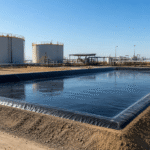
Floating covers are used on reservoirs, industrial wastewater ponds, process water storage, leachate basins, and environmental containment systems where open-water exposure creates operational risk. A properly designed floating cover can reduce sunlight penetration, limit airborne contamination, lower VOC release, control odor, and protect stored water from wind-driven debris. The cover system is not only a geomembrane sheet. It includes material selection, welded seams, edge sealing, buoyancy support, anchoring, venting, drainage, and maintenance access. For engineering projects, HDPE and LLDPE geomembranes are commonly selected based on chemical exposure, UV resistance, water-level movement, wind load, and site geometry.
Algae Growth Prevention
A floating cover helps control algae growth by reducing sunlight exposure, limiting wind-driven mixing, and lowering the amount of airborne debris entering the reservoir. Algae growth is usually linked to three conditions: light, nutrients, and warm stagnant surface water. A black HDPE or LLDPE geomembrane floating cover can block most photosynthetically active light from reaching the water surface when seams, overlaps, edges, and access openings are properly closed. In municipal water storage, irrigation reservoirs, industrial ponds, and wastewater-related containment, algae control should also include nutrient input reduction, regular water quality testing, and inspection of cover movement after wind, rain, or water-level changes.
Light Blocking Performance
Algae need sunlight for photosynthesis. In open reservoirs, the surface layer receives direct solar radiation every day, especially in warm climates, shallow zones, and low-flow areas. A floating cover reduces this exposure by placing an opaque barrier directly on the water surface.
For reservoir protection, the cover material should be selected for:
- Opaque surface color: Black geomembrane is commonly used because it limits light penetration.
- UV resistance: Outdoor exposed covers need UV-stabilized material. Black HDPE geomembrane formulations commonly use carbon black content around 2%–3%.
- Suitable thickness: Floating covers are often designed with geomembrane thickness such as 1.0 mm, 1.5 mm, or 2.0 mm, depending on wind exposure, installation method, cover movement, and maintenance access.
- Low light leakage at joints: Welded seams, sealed penetrations, and controlled edge details are as important as the sheet surface.
A cover with good material opacity can still perform poorly if it has gaps, loose edges, open inspection ports, or poorly sealed pipe penetrations. These areas allow sunlight and debris to enter the water, which can support localized algae growth near edges or service openings.
| Control Point | Engineering Purpose | Practical Check |
|---|---|---|
| Black geomembrane surface | Reduces light entry into the water | Check for exposed water zones |
| Welded seams | Reduces light leakage between panels | Inspect seam continuity and wrinkles |
| Edge sealing | Limits light and debris at reservoir perimeter | Check anchor trench or perimeter fixing |
| Access openings | Allows maintenance without leaving gaps open | Use sealed hatches or controlled covers |
| Floating movement | Keeps cover in contact with water surface | Check wind displacement after storms |
For material selection, LLDPE geomembrane is often useful where the cover needs flexibility, such as floating covers with frequent movement, irregular reservoir shapes, or changing water levels. HDPE geomembrane is often used where chemical resistance, UV exposure resistance, and higher stiffness are required. The final choice should match reservoir geometry, water chemistry, wind conditions, and installation method.
A practical design target is not only “dark material,” but continuous light control across the whole exposed surface. If 5%–10% of the water surface remains uncovered near edges, corners, or equipment zones, algae may still develop in those areas during warm seasons.
Nutrient Input Control
Light reduction is only one part of algae prevention. Algae also need nutrients, mainly nitrogen and phosphorus. A floating cover cannot remove existing nutrients from the water. It helps reduce new nutrient input by limiting direct contact between water and external contamination sources.
Common nutrient sources include:
- stormwater runoff carrying soil, fertilizer, or organic matter;
- bird droppings and animal access near open water;
- leaves, dust, and airborne organic debris;
- wastewater inflow with high nutrient concentration;
- sediment disturbance in shallow zones;
- poorly controlled inlet structures.
A floating cover can reduce windblown debris and bird access, but it should be combined with site-level controls. For reservoirs used in municipal water storage, irrigation, industrial process water, or environmental containment, nutrient control should start before water enters the reservoir.
Recommended control measures include:
- Inlet screening: Use screens, sediment traps, or forebays where suspended solids may enter the reservoir.
- Runoff separation: Keep stormwater from flowing directly into the reservoir unless it is part of the designed system.
- Bank and slope stabilization: Use erosion control measures around the reservoir to reduce soil and organic material entering the water.
- Animal access control: Perimeter fencing, bird deterrent design, and covered edges can reduce biological contamination.
- Sludge and sediment review: Bottom sediment can release nutrients back into the water, especially under low-oxygen conditions.
For reservoirs with a geomembrane liner system, nutrient control should also consider the relationship between the floating cover and the bottom liner. If sludge accumulates on the liner surface, operators should plan removal intervals based on solids loading, water depth, and access conditions. Cleaning tools should not be dragged directly across exposed geomembrane surfaces unless protection methods are in place.
A simple inspection checklist can be used during operation:
- Are inlet zones showing visible algae or floating debris?
- Is runoff entering from slopes, roads, or nearby soil areas?
- Are leaves or organic materials collecting near cover folds?
- Are birds or animals accessing the water edge?
- Is sediment accumulation visible at shallow areas?
- Are nutrient test results increasing over time?
For water quality tracking, operators usually monitor parameters such as total nitrogen, total phosphorus, turbidity, pH, dissolved oxygen, temperature, and chlorophyll-a where algae risk is a concern. The exact test plan should match reservoir use, water source, and project requirements.
Water Quality and Odor Management
Algae growth can affect water appearance, odor, dissolved oxygen levels, and maintenance frequency. In covered reservoirs, water quality management should focus on preventing stagnant pockets, controlling organic load, and checking whether the floating cover creates trapped gas or odor zones.
A floating cover changes the air-water interface. It reduces sunlight and surface contamination, but it also reduces direct atmospheric exchange. The design should consider venting, water circulation, inlet and outlet layout, and inspection access.
| Condition | Possible Effect | Management Method |
|---|---|---|
| Warm surface water | Faster biological activity | Monitor water temperature and turnover |
| Low dissolved oxygen | Odor and anaerobic conditions | Review circulation and inlet/outlet design |
| Organic debris under cover | Local odor formation | Remove debris during scheduled inspection |
| Poor cover drainage | Ponding on top of cover | Add drainage sumps or pump-off points |
| Trapped gas pockets | Cover lifting or odor release | Include controlled venting where needed |
| Stagnant corners | Local algae or biofilm growth | Adjust cover layout and water movement |
Odor is not always caused by algae alone. It can also come from anaerobic decomposition, sludge buildup, sulfide formation, or trapped gases under the cover. For industrial wastewater ponds or reservoirs with organic loading, odor management should not rely only on covering the surface. The project should evaluate water chemistry, sludge depth, gas formation, and maintenance access.
Floating cover design should include practical inspection routes. Operators need safe access to check:
- welded seams and cover tension;
- floating modules or buoyancy lines;
- pipe penetrations and hatches;
- rainwater collection points;
- edge anchoring and perimeter sealing;
- odor release points after water-level changes.
If the floating cover includes ballast tubes, floats, or tensioning systems, these components should not create large folds where debris can collect. Folded areas can hold rainwater above the cover and organic matter below the cover. Both conditions increase maintenance work and may affect water quality near the surface.
For many reservoir projects, the material system may include:
- LLDPE geomembrane floating cover for flexibility and movement tolerance;
- HDPE geomembrane liner for base containment where chemical resistance and stiffness are needed;
- PET non-woven geotextile protection layer under liner zones with higher puncture risk;
- textured geomembrane on slopes where interface friction and slip resistance need review.
Algae prevention should be treated as a system requirement. The cover reduces light, the site design limits nutrient input, and the operation plan manages water quality, odor, and inspection access. Without all three, algae may still appear near open edges, inlet zones, access hatches, or shallow stagnant areas.
VOC Emission Control
A floating cover can reduce VOC release from reservoirs, industrial wastewater ponds, and process water storage by limiting direct contact between contaminated water and open air. VOC control depends on cover material, surface coverage, welded seam quality, edge sealing, vent layout, and gas handling design. For ponds containing hydrocarbons, solvents, leachate, or high-organic wastewater, the cover should be selected after chemical compatibility review, not only by thickness. HDPE geomembrane is often used where chemical resistance and UV exposure are major concerns, while LLDPE geomembrane is useful when the cover must tolerate movement, settlement, and irregular geometry. Good VOC control requires sealed edges, controlled venting, and scheduled inspection after wind, rain, and water-level changes.
Vapor Barrier Material Selection
VOC emission control starts with the vapor barrier material. A floating cover cannot perform well if the geomembrane is not compatible with the stored liquid, expected vapor concentration, operating temperature, and outdoor exposure conditions.
For reservoir and industrial pond covers, the most common material options are HDPE geomembrane and LLDPE geomembrane.
| Material Option | Suitable Conditions | Design Notes |
|---|---|---|
| HDPE geomembrane | Hydrocarbon contact, chemical containment, UV-exposed ponds, industrial wastewater | Higher stiffness; good chemical resistance; needs careful detailing around folds and corners |
| LLDPE geomembrane | Floating covers with movement, variable water levels, irregular pond shapes, flexible cover systems | Better flexibility; useful where cover movement and settlement are expected |
| Textured geomembrane | Slopes, sidewalls, areas needing higher interface friction | Mainly used where slip resistance matters, not as the first choice for floating areas |
| PET non-woven geotextile | Protection layer under liner or high-puncture-risk zones | Used for puncture protection, separation, and cushioning; not a vapor barrier |
For VOC control, thickness alone is not enough. A 2.0 mm geomembrane may still perform poorly if seams, edges, and pipe penetrations are not sealed. A thinner but properly welded and sealed cover may provide better field performance than a thicker sheet with open gaps.
Common geomembrane thickness ranges for floating cover systems include:
- 1.0 mm: lighter-duty applications with lower mechanical stress;
- 1.5 mm: common range for many reservoir and wastewater cover projects;
- 2.0 mm: higher mechanical stress, stronger wind exposure, or more demanding industrial service.
Material selection should check:
- chemical compatibility with stored liquid and vapor;
- resistance to hydrocarbons, oils, solvents, or organic compounds;
- UV resistance for exposed outdoor service;
- carbon black content, commonly around 2%–3% for black HDPE formulations;
- oxidative resistance, often reviewed through OIT or HPOIT testing;
- stress crack resistance for HDPE geomembrane;
- flexibility requirements during water-level movement;
- welding method and seam testing plan.
For chemical exposure, project teams should not assume all geomembranes behave the same. Hydrocarbon exposure, high-temperature wastewater, acidic wastewater, alkaline wastewater, and solvent-containing liquid may affect polymer performance differently. Before final material approval, the stored liquid profile should be reviewed with the geomembrane supplier, especially when VOCs are associated with fuels, oils, leachate, or industrial process water.
A practical material review should include:
- Liquid composition: Identify hydrocarbons, solvents, acids, alkalis, salts, oils, surfactants, and organic load.
- Operating temperature: Higher temperature can increase vapor pressure and may accelerate material aging.
- Exposure condition: Check whether the cover will be continuously exposed to sunlight, wind, rainwater, and floating debris.
- Mechanical movement: Floating covers move with water-level change, wind load, waves, and gas pressure. Material flexibility matters.
- Seam reliability: Field welding, trial seams, destructive testing, and non-destructive seam testing should be planned before installation.
For VOC service, the cover should be treated as a containment component, not just a surface sheet. The material must work together with seams, penetrations, anchoring, ballast, vents, and gas handling equipment.
Edge Sealing Design
Even when the central cover sheet has low vapor transmission, VOCs can still escape through poorly sealed edges. Edge sealing is one of the most common weak areas in floating cover systems because the cover must move with water-level changes while still reducing vapor release.
Edge sealing design should consider:
- water-level fluctuation range;
- wind uplift pressure;
- reservoir side slope angle;
- anchoring method;
- perimeter access requirements;
- wave movement near the bank;
- rainwater drainage on top of the cover;
- pipe penetrations, overflow zones, and inspection points.
Typical edge details may include anchor trenches, perimeter batten systems, ballast tubes, floating skirts, flexible flashing, or sealed transition strips. The correct method depends on whether the reservoir has concrete walls, compacted earth slopes, lined embankments, or steel/concrete containment structures.
| Edge Area | VOC Risk | Control Method |
|---|---|---|
| Perimeter bank | Vapor leakage along open edges | Anchor trench, ballast tube, or sealed perimeter strip |
| Pipe penetration | Leakage around inlet, outlet, or monitoring pipe | Prefabricated boot, welded collar, clamp detail, compatible sealant |
| Access hatch | Vapor escape during inspection | Gasketed hatch or controlled opening design |
| Overflow point | Cover displacement and open water exposure | Reinforced transition and protected overflow detail |
| Corners and irregular shapes | Wrinkles and gaps | Flexible detailing and extra field fitting |
| Water-level change zone | Pulling, folding, or tension stress | Slack allowance and floating edge design |
A good edge design should not pull the cover too tight. Floating covers need controlled slack to move with water level, but excessive slack can create folds where gas, debris, or rainwater collects. Both conditions affect VOC control and maintenance.
Important edge sealing checks include:
- no continuous open gap between cover and bank;
- no exposed water strip along the perimeter;
- no sharp concrete edge cutting into the geomembrane;
- no unsupported pipe penetration;
- no loose clamp or unsealed collar;
- no edge uplift after strong wind;
- no rainwater load pulling the cover away from the perimeter.
For lined reservoirs, the floating cover should also be coordinated with the bottom and side liner system. If the reservoir uses an HDPE geomembrane liner, the edge transition between bottom liner, side slope liner, and floating cover must be planned before installation. Poor coordination at this transition can cause wrinkles, stress concentration, or difficult seam access.
Wind conditions also affect edge sealing. In open sites, wind can lift loose cover edges, expose water, and increase vapor release. A cover used in windy regions should include ballast, tension control, and inspection after storm events. For larger reservoirs, wind uplift review should include cover panel size, float layout, anchoring points, and maintenance access.
Recommended inspection points:
- perimeter seal continuity;
- anchor trench settlement;
- ballast tube position;
- seam condition near the edge;
- cover movement after water-level change;
- exposed water near corners;
- pipe penetration sealing;
- odor release near access points.
If odor is strongest near the perimeter, the first inspection should focus on edge gaps, open hatches, pipe penetrations, and wind-lifted cover areas.
Gas Collection and Venting
A floating cover can reduce uncontrolled VOC release, but it may also trap vapor under the cover. For industrial wastewater ponds, leachate storage, hydrocarbon-contaminated water, or process reservoirs, gas collection and venting should be planned as part of the cover system.
Without controlled venting, vapor pressure may accumulate under the cover. This can cause cover lifting, ballooning, stress around seams, odor release during access opening, or unsafe working conditions around inspection points. The design should allow gas to move toward controlled collection or vent points instead of escaping randomly through seams and edges.
Gas handling options may include:
- passive vents for low vapor load conditions;
- vent risers with weather protection;
- gas collection headers;
- flexible gas collection lines;
- condensate traps or drain points;
- connection to activated carbon treatment;
- connection to vapor treatment equipment where required;
- pressure relief points designed by the project engineer.
The correct option depends on VOC concentration, vapor flow rate, water temperature, pond size, cover area, and site safety requirements.
| Design Item | Function | Field Concern |
|---|---|---|
| Vent riser | Releases or directs trapped vapor | Must be protected from rainwater entry |
| Collection header | Moves vapor to treatment or control point | Needs slope and condensate management |
| Pressure relief | Prevents cover lifting from gas buildup | Must not become an uncontrolled emission path |
| Condensate drain | Removes condensed liquid from gas lines | Needs safe access and maintenance |
| Gas treatment connection | Sends vapor to carbon or other treatment | Must match vapor type and flow rate |
| Inspection port | Allows monitoring and maintenance | Should be sealed when not in use |
For VOC control, venting does not mean simply opening holes in the cover. Random openings reduce cover efficiency and may create odor release points. Venting should be deliberate, located, protected, and connected to monitoring or treatment where needed.
Gas collection design should consider cover slope and floating geometry. Gas tends to collect at high points under the cover. If the floating cover has folds, raised areas, or uneven float spacing, vapor can accumulate in pockets. These pockets may increase stress on seams and make odor more noticeable during maintenance.
Good gas management usually includes:
- Defined gas flow paths: The cover should guide vapor toward selected vent or collection points.
- Controlled pressure release: Pressure should not lift the cover or force vapor through weak edge areas.
- Condensate handling: VOC vapor streams can contain moisture. Condensed liquid can block gas lines if drainage is not planned.
- Sealed inspection access: Hatches and ports should close tightly after maintenance.
- Monitoring plan: Odor checks, gas readings, and visual inspection should be scheduled based on the stored liquid risk.
For reservoirs with low VOC potential, simple venting may be enough. For industrial wastewater or hydrocarbon-related containment, gas collection may need to connect to a treatment unit. Activated carbon is often used for certain organic vapor streams, but suitability depends on vapor composition, humidity, concentration, and service conditions.
Operational teams should check the cover after:
- rapid water-level rise or drawdown;
- strong wind;
- heavy rain;
- warm weather periods;
- changes in wastewater composition;
- odor complaints near the reservoir;
- visible ballooning or lifted cover sections.
VOC emission control is a system problem. The geomembrane provides the vapor barrier, edge sealing limits leakage, and venting moves trapped gas to controlled points. If one part is ignored, VOCs may escape through perimeter gaps, access hatches, pipe penetrations, or stressed seams.
Buoyancy Systems
A buoyancy system keeps a floating reservoir cover in controlled contact with the water surface while allowing movement during water-level changes, wind loading, rainfall, and maintenance access. For HDPE or LLDPE geomembrane floating covers, buoyancy design normally includes float spacing, ballast lines, perimeter anchoring, drainage sumps, access zones, vents, and tension control. Float spacing is project-specific, but preliminary layouts often tighten spacing near vents, pump points, corners, pipe penetrations, and inspection routes. The system must support the cover weight, rainfall ponding load, localized maintenance load, and wind uplift without overstressing welded seams or exposing open water.
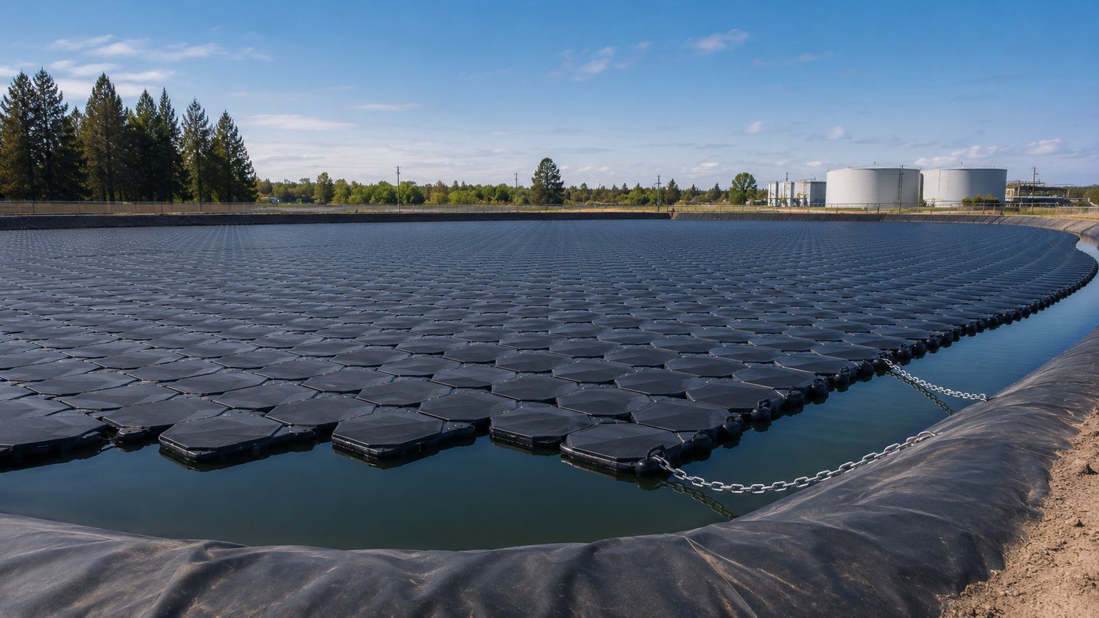
Float Layout and Spacing
Float layout determines how evenly the cover moves on the reservoir surface. Poor spacing can create deep folds, trapped gas pockets, rainwater ponding, seam stress, and uncovered water zones near edges. A good layout does not make the cover rigid. It allows controlled movement while keeping the geomembrane surface stable.
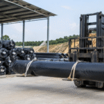
Common buoyancy components include:
- HDPE pipe floats for long floating lines and perimeter support;
- closed-cell polyethylene foam floats inside protective sleeves;
- geomembrane-wrapped flotation logs for controlled buoyant zones;
- ballast tubes to resist uplift and keep cover geometry stable;
- floating drainage sump supports for rainwater pump-off areas;
- access floats for inspection routes and service points.
The correct float type depends on cover area, water-level fluctuation, wind exposure, reservoir geometry, chemical exposure, and maintenance method.
| Design Area | Buoyancy Requirement | Field Control Point |
|---|---|---|
| Central cover field | Prevents excessive sagging and folding | Check float line spacing and panel movement |
| Rainwater collection zone | Supports water load above the cover | Place floats around sump and pump points |
| Pipe penetrations | Reduces stress around fixed details | Add localized float support and flexible boots |
| Vent locations | Keeps gas paths stable | Avoid low spots that trap vapor |
| Perimeter zone | Controls edge movement | Combine floats with ballast or anchor details |
| Access route | Supports inspection and maintenance load | Use reinforced floating support where needed |
Float spacing should be calculated, not guessed. The layout should consider:
- Geomembrane weight: Thicker geomembrane has higher self-weight. A 1.5 mm or 2.0 mm cover needs more support than a lighter cover.
- Rainfall load: Rainwater on top of the cover can create localized load. Even 50 mm of standing rainwater equals about 50 kg/m² of added load.
- Wind and wave movement: Large exposed reservoirs need closer review of uplift, wave movement, and cover drift.
- Water-level fluctuation: Floating covers must rise and fall without tearing at anchors, penetrations, or welded transitions.
- Maintenance access: Walk-on access zones need reinforcement and flotation support. They should not rely only on the geomembrane sheet.
As an early design reference, float lines may be placed closer in high-load zones and wider in low-load central areas, but final spacing should be set by project engineering. For large reservoirs, the difference between a stable cover and a high-maintenance cover is often the spacing around corners, sumps, vents, and penetrations, not only the spacing in the open center.
A practical float layout review should check:
- Are floats aligned with cover drainage direction?
- Are rainwater sump areas supported on all sides?
- Are vents located at high points under the cover?
- Are pipe penetrations protected from pulling stress?
- Are float sleeves welded continuously without sharp folds?
- Are access zones separated from thin unsupported cover areas?
- Are float lines arranged to reduce cover twisting during wind?
For material selection, LLDPE geomembrane is often preferred for floating covers with frequent movement because it has better flexibility than HDPE. HDPE geomembrane is often selected where chemical resistance, UV exposure, and dimensional stability are stronger design requirements. In high-puncture-risk areas near concrete edges, equipment zones, or rough subgrade transitions, a PET non-woven geotextile protection layer may be used below liner areas, but it does not replace the buoyancy system.
Wind Uplift Resistance
Wind can lift, fold, displace, or overstress a floating cover. The risk increases on large reservoirs, open terrain, high side slopes, and sites without wind breaks. Wind action affects the exposed surface, seams, edges, floats, ballast tubes, vents, and pipe penetrations.
A floating cover should be reviewed for:
- uplift at loose edges;
- cover billowing between float lines;
- open water exposure near the perimeter;
- stress around fixed penetrations;
- movement of ballast tubes;
- seam fatigue caused by repeated movement;
- rainwater redistribution after wind events.
Wind uplift control usually combines cover weight, ballast, float layout, anchoring, perimeter sealing, and controlled slack. A cover that is too tight can tear at fixed details. A cover that is too loose can fold, collect rainwater, and move excessively during storms.
| Wind Risk | Likely Effect | Design Response |
|---|---|---|
| Loose perimeter edge | Open water exposure and vapor release | Add ballast, sealed edge detail, or anchor control |
| Wide unsupported cover span | Billowing and seam movement | Reduce float spacing or add support lines |
| Strong gusts across open reservoir | Cover displacement | Review ballast weight and perimeter restraint |
| Poor drainage on cover surface | Rainwater ponding after wind | Add sump support and pump-off route |
| Fixed pipe penetration | Tearing or local stress | Use flexible boot and reinforced floating support |
| High gas pressure under cover | Cover lifting from below | Add controlled venting and gas collection |
Wind resistance should be checked together with rainfall drainage. A cover lifted by wind can shift rainwater into low spots, increasing localized loading. If 100 m² of cover area collects 50 mm of water, that ponded area carries about 5,000 kg of water load. The cover system must drain or support this load without pulling seams or exposing reservoir water.
For outdoor geomembrane covers, UV resistance also matters because wind movement and sunlight exposure act together over time. Black HDPE and LLDPE geomembranes commonly use carbon black for UV stabilization, often around 2%–3% in properly formulated materials. The project should also review thickness, antioxidant properties, stress crack resistance, and welding performance.
Wind uplift resistance should not depend on one detail. A stable system normally includes:
- perimeter anchor trench or mechanical fixing;
- ballast tubes along selected lines;
- controlled slack for water-level movement;
- reinforced seams near high-stress zones;
- protected pipe boots and access hatches;
- drainage points for rainwater pump-off;
- venting to reduce trapped gas pressure;
- inspection after high-wind events.
Post-wind inspection checklist:
- Check whether any edge has lifted or shifted.
- Look for exposed water near corners or bank transitions.
- Inspect ballast tubes for rolling or displacement.
- Check wrinkles near welded seams.
- Inspect pipe penetrations for pulling marks.
- Confirm that rainwater pumps and sump zones still work.
- Check vents for blockage, tilting, or water entry.
- Record cover movement patterns for later adjustment.
If repeated wind movement occurs in the same area, adding more ballast may not be enough. The layout may need float adjustment, seam reinforcement, improved drainage, or a different edge restraint detail.
Anchor and Tension Design
Anchoring controls the relationship between the floating cover and the reservoir perimeter. Tension design controls how the cover moves without overstressing seams, penetrations, and edge details. These two parts must be designed together.
Common anchoring methods include:
- anchor trench in compacted soil embankments;
- mechanical batten fixing on concrete structures;
- deadman anchors outside the reservoir edge;
- perimeter ballast tubes for flexible edge restraint;
- cable or strap systems for tension control;
- transition strips between floating cover and fixed liner zones.
The anchor detail should match the reservoir structure. A concrete tank edge, HDPE-lined embankment, compacted earth slope, and steel containment wall all need different fixing methods.
| Anchor Method | Suitable Area | Design Concern |
|---|---|---|
| Anchor trench | Earth embankment reservoirs | Soil compaction, trench size, cover pullout resistance |
| Mechanical batten | Concrete wall or rigid edge | Bolt spacing, gasket, liner compression, corrosion resistance |
| Deadman anchor | Sites needing external restraint | Load transfer and access for maintenance |
| Ballast tube | Floating or semi-floating edge | Rolling, displacement, and water-level movement |
| Cable tension system | Large covers with controlled geometry | Over-tensioning and connection stress |
| Flexible transition strip | Pipe or irregular edge zones | Wrinkling, sealing, and field fitting |
A typical anchor trench is often designed with project-specific dimensions based on soil condition, slope geometry, cover stress, and installation method. Generic trench dimensions should not be copied into a project without calculation. Poor trench compaction, sharp trench edges, and insufficient cover embedment can reduce pullout resistance.
Tension design should allow movement. A floating cover must respond to:
- normal water-level rise and drawdown;
- thermal expansion and contraction;
- wind movement;
- wave action;
- rainfall loading;
- gas pressure below the cover;
- maintenance access load.
Over-tensioning is a common installation problem. It may make the cover look clean after installation, but it can increase stress when the water level changes. Under-tensioning creates large folds, rainwater pockets, and unstable wind behavior. The correct condition is controlled slack with defined movement paths.
Installation control should include:
- Panel layout review: Cover panels should be positioned so seams do not concentrate stress at corners, drains, vents, or pipe penetrations.
- Trial welding and seam testing: Field welding should include trial seams, temperature control, pressure setting, and seam inspection. Double-wedge seams may be air-channel tested where applicable. Extrusion welds may require vacuum box or spark testing depending on detail and material.
- Edge detail inspection: Anchors, battens, ballast tubes, and transition strips should be checked before water-level changes.
- Tension adjustment: Final tension should be checked after the cover floats, not only while panels are dry on the bank.
- Penetration protection: Pipe boots, vents, hatches, and sump details should allow movement without tearing the geomembrane.
For floating cover systems, anchor and tension design should also account for thermal movement. Dark geomembrane surfaces can heat significantly under direct sunlight. This can expand the sheet during the day and contract it at night. If the cover is fixed too rigidly, repeated movement may stress seams and edge details.
Recommended maintenance checks:
- perimeter anchor condition;
- batten bar tightness and gasket condition;
- ballast tube position;
- cover slack after water-level change;
- wrinkles near fixed penetrations;
- seam condition near anchor points;
- tension cable or strap wear;
- exposed sharp edges at concrete or metal contact points;
- settlement near anchor trenches.
The safest design approach is to treat buoyancy, wind resistance, anchoring, and tension as one system. Floats support the cover, ballast controls movement, anchors restrain the perimeter, and tension design prevents stress concentration. If one part is undersized or poorly installed, the cover may still float, but inspection frequency and repair risk will increase.