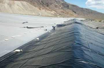

- An approved landfill liner design and panel layout.
- Qualified geomembrane installers and suitable welding equipment.
- Independent construction quality assurance, or CQA.
- Traceable inspection, testing, repair, and as-built records.
In the United States, the federal design standard for municipal solid waste landfill units defines a composite liner as a flexible membrane liner over a compacted soil component. Where HDPE is used under that federal standard, the geomembrane must be at least 60 mil thick. This is a regulatory reference, not a universal specification for every country or landfill type. Local regulations, permit conditions, project drawings, and the site-specific CQA plan remain controlling documents. (eCFR, 40 CFR §258.40)
This guide explains the practical installation sequence without presenting welding temperatures, machine speeds, anchor trench dimensions, test pressures, or sampling frequencies as universal values. Those parameters must be established by the approved project specification, geomembrane manufacturer, trial weld results, and CQA engineer.
Understand the Landfill Base Liner Before Installation
The Geomembrane Is One Component of a Composite System
An HDPE geomembrane creates a low-permeability barrier, but a landfill base liner normally depends on several materials working together.
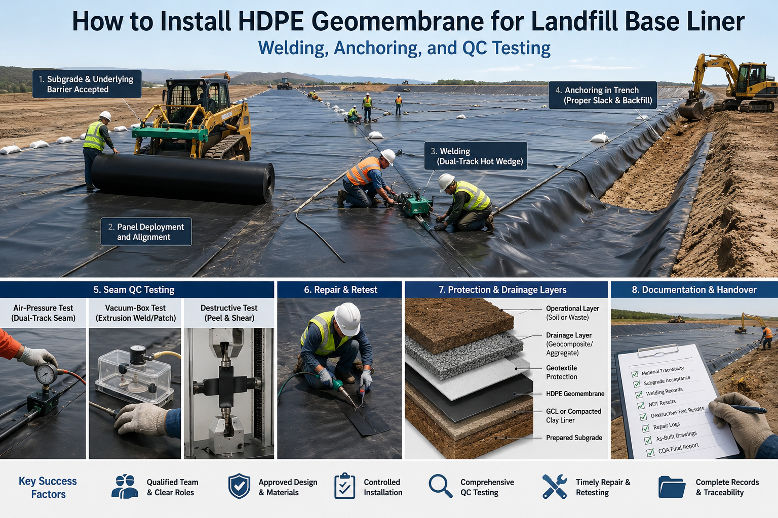
A typical system may include, from bottom to top:
- Prepared subgrade.
- Compacted clay liner or geosynthetic clay liner.
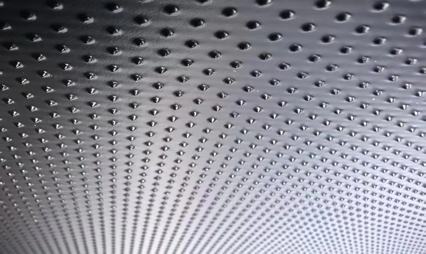
- Smooth or textured HDPE geomembrane.
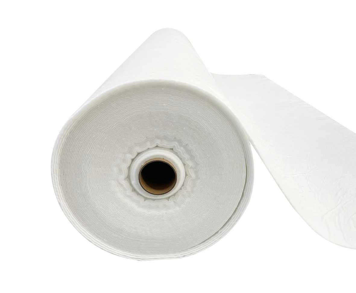
- Protective nonwoven geotextile.
- Geocomposite or aggregate drainage layer.
- Perforated leachate collection pipes.
- Operational protection soil or waste-placement layer.
The exact sequence differs by design. Some projects use a single composite liner, while higher-risk facilities may use primary and secondary geomembranes separated by a leak detection layer.
The International Geosynthetics Society notes that composite barriers can reduce contaminant release substantially compared with a geomembrane or compacted clay layer acting alone. Intimate contact between the geomembrane and the underlying low-permeability layer is particularly important because wrinkles, bridging, or voids can increase leakage if the sheet is later damaged. (International Geosynthetics Society)
For a more detailed explanation of the system layers, see Jinseed’s guide to landfill bottom liner system layers.
Separate Design, Installation, CQC, and CQA Responsibilities
A reliable project separates responsibilities instead of allowing one party to approve its own work.
The main roles usually include:
- Design engineer: Defines materials, interfaces, slopes, anchorage, penetrations, acceptance criteria, and the CQA plan.
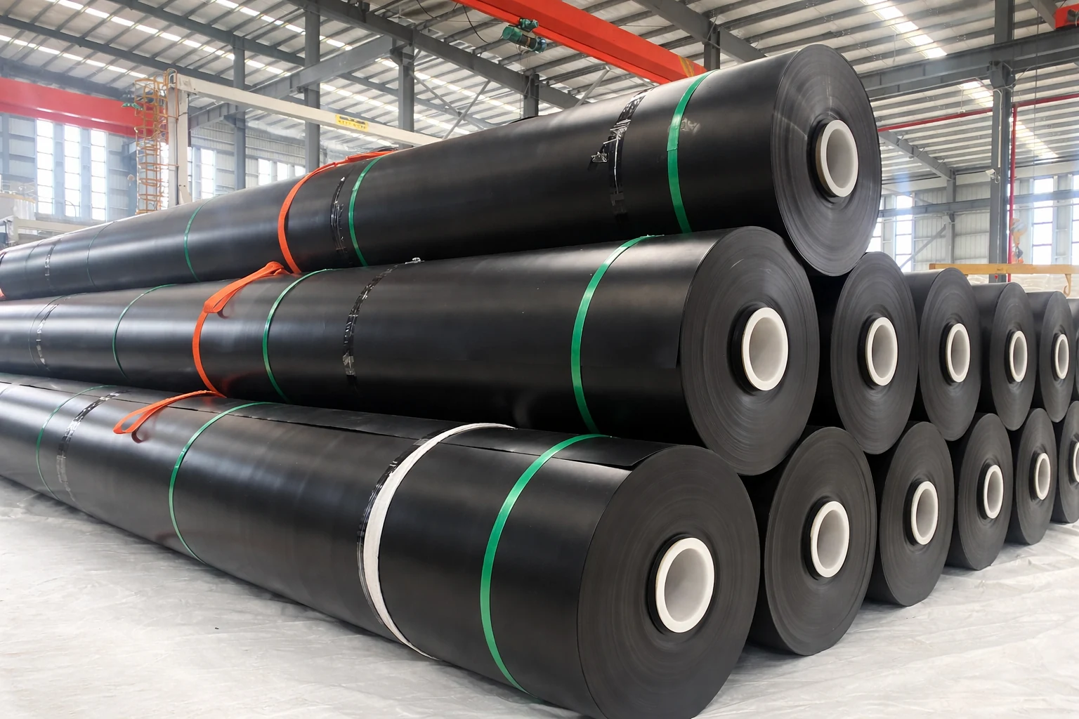
- Geomembrane manufacturer: Supplies rolls, manufacturing quality control certificates, roll identification, and material test data.
- Installation contractor: Deploys panels, performs welding, conducts construction quality control, and repairs identified defects.
- CQA personnel: Observe the work independently, verify compliance, witness testing, review records, and document deviations.
- Owner or operator: Controls site access, work sequencing, approvals, and final acceptance.
Construction quality control, or CQC, is performed by the installer to control its own work. Construction quality assurance, or CQA, provides independent observation and verification on behalf of the owner or responsible engineer.
EPA technical guidance identifies material preparation, welding equipment, trial seams, field seaming, inspection, testing, and documentation as essential parts of geomembrane construction quality assurance. (U.S. EPA)
Complete the Pre-Installation Review
Confirm the Approved Documents
Installation should not begin from a material quotation or general construction drawing alone. The site team should have the latest approved versions of:
- Liner system drawings.
- Technical specifications.
- CQA plan.
- Panel layout or deployment plan.
- Anchor trench and termination details.
- Pipe penetration and concrete attachment details.
- Material submittals and manufacturer certificates.
- Welding and testing procedures.
- Repair procedures.
- Health and safety plan.
- Rainwater and surface-water management plan.
The CQA team should verify the revision number of every controlled document. An outdated slope detail or penetration drawing can create an installed condition that cannot be corrected without removing completed liner work.
Verify Material Traceability at Delivery
Each geomembrane roll should be checked before unloading and again before deployment.
The receiving record should normally identify:
- Manufacturer.
- Product type and surface finish.
- Nominal thickness.
- Roll number.
- Resin batch or production lot where available.
- Roll width and length.
- Production date.
- Packaging condition.
- Visible transit damage.
- Storage location.
- Corresponding manufacturing QC certificate.
GRI-GM13 provides material property and testing requirements for smooth and textured HDPE geomembranes. It covers properties such as thickness, density, tensile performance, tear resistance, puncture resistance, carbon black content and dispersion, stress crack resistance, and oxidative induction time. The project specification should identify the required edition and any project-specific values. (Geosynthetic Institute, GRI-GM13)
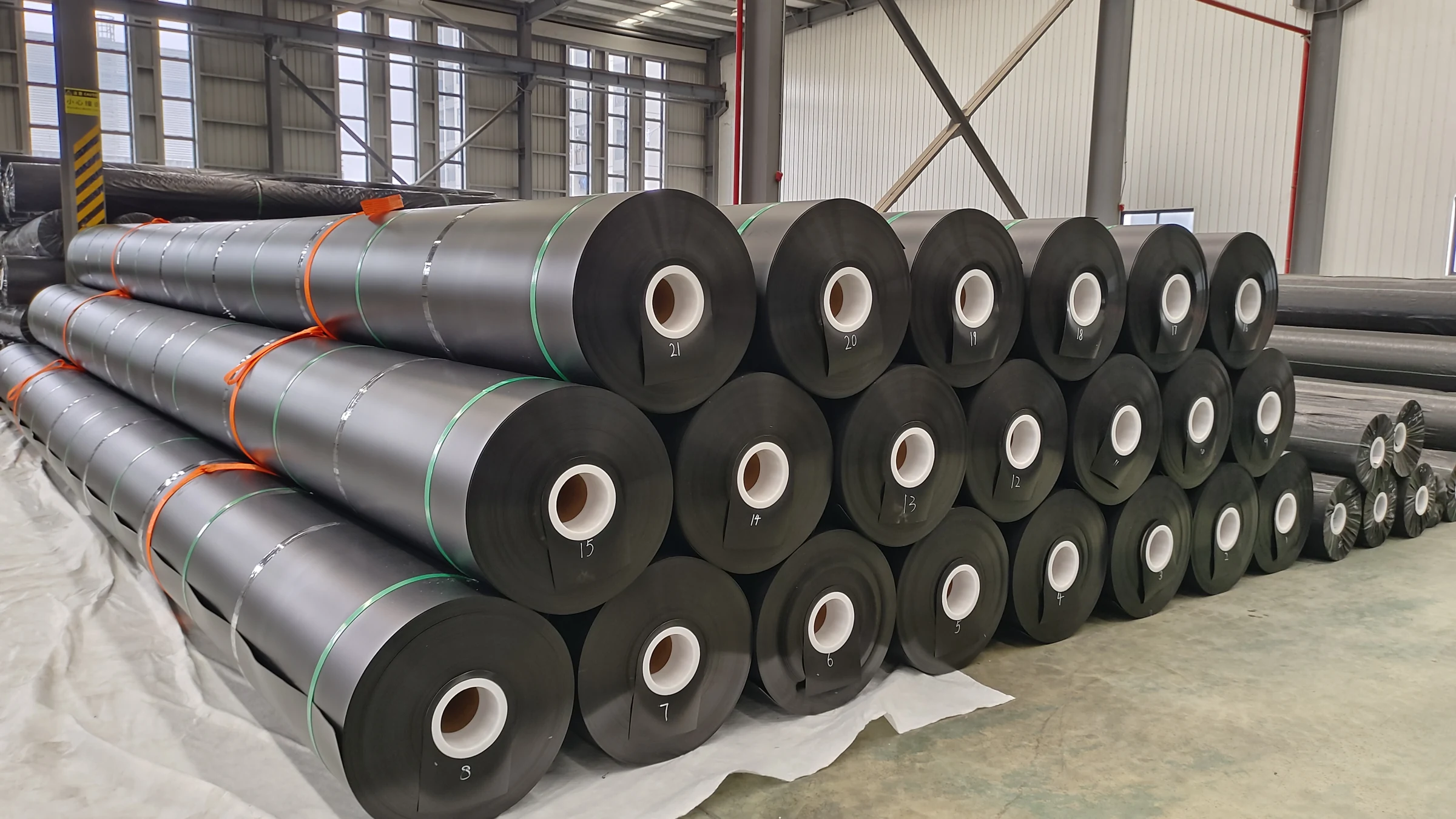
Rolls should not be dragged, dropped, pushed directly with unprotected equipment, or lifted in a way that damages their cores or edges. Damaged roll edges can later become seam defects when contaminated or distorted material enters the welding area.
Store the Rolls on a Suitable Surface
Storage areas should be firm, dry, accessible to lifting equipment, and separated from standing water, sharp debris, fuel, solvents, and active traffic routes.
The storage arrangement should prevent:
- Roll deformation.
- Damage to protective wrapping.
- Contamination by mud or aggregate.
- Uncontrolled rolling.
- Excessive stacking loads.
- Loss of roll identification.
- Mixing of accepted and rejected materials.
The delivery sequence should also match the deployment plan. Moving heavy rolls repeatedly around the site increases handling risk and wastes installation time.
Accept the Subgrade and Underlying Barrier
Inspect the Surface Before Panel Deployment
The geomembrane should only be deployed after the underlying layer has been formally accepted.
The prepared surface should be:
- Stable under construction foot traffic.
- Smooth and free from abrupt elevation changes.
- Free from exposed stones, roots, metal, glass, waste, and other sharp objects.
- Free from standing water, mud, ice, and soft areas.
- Graded to the approved elevations and drainage direction.
- Free from unapproved penetrations or temporary stakes.
- Suitable for intimate contact with the geomembrane.
A subgrade that appears visually smooth can still contain isolated hard points. The CQA inspection should cover the full deployment area, including transitions, slope toes, sump zones, pipe trenches, and perimeter terminations.
The accepted area should be limited to the amount that can reasonably be covered before rain, erosion, desiccation, construction traffic, or wind changes its condition.
Protect a GCL or Compacted Clay Layer
Where a geosynthetic clay liner is installed beneath the HDPE geomembrane, the GCL should be protected from premature hydration, displacement, contamination, and damage during geomembrane deployment.
Where compacted clay is used, the site team should prevent:
- Desiccation cracking.
- Erosion.
- Rutting.
- Freezing.
- Standing water.
- Surface contamination.
- Damage from equipment turning or braking.
If the accepted clay or GCL surface is damaged after approval, the affected area must be repaired and reaccepted before geomembrane deployment continues.
Jinseed’s comparison of GCL and compacted clay liners explains why the installation controls for these two underlying barriers are different.
Establish a Formal Subgrade Acceptance Record
A useful subgrade acceptance form should identify:
- Area or grid accepted.
- Date and time.
- Weather conditions.
- Underlying material.
- Survey status.
- Observed defects.
- Corrective actions.
- Installer representative.
- Earthwork contractor representative.
- CQA representative.
- Restrictions or unresolved items.
This creates a clear transfer of responsibility. Once the installer accepts an area and deploys the geomembrane, later claims that the subgrade was unsuitable become more difficult to evaluate without a signed record.
Plan the Panel Layout and Deployment Sequence
Reduce Field Seams Where Practical
The panel layout should use available roll dimensions efficiently while accounting for slopes, anchor trenches, sumps, penetrations, access routes, and installation direction.
A good layout aims to:
- Reduce unnecessary field seams.
- Avoid four-panel intersections.
- Keep complex seam intersections away from sumps and penetrations.
- Limit cross-slope seams where the design discourages them.
- Avoid seams through known areas of concentrated stress.
- Provide access for welding and testing equipment.
- Identify every panel with a unique number.
- Coordinate with the construction sequence for drainage components.
Larger rolls can reduce the total seam length, but only when the site has suitable lifting equipment, deployment access, and crew capacity. Selecting the widest possible roll without checking site handling conditions can increase deployment damage.
Deploy Panels Without Damaging the Underlying Layer
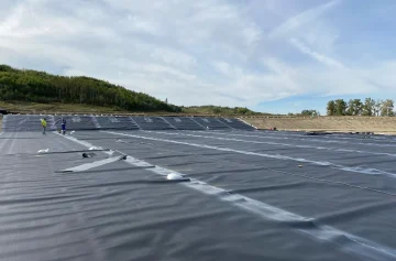
Geomembrane panels are normally unrolled using equipment that supports the roll core or a purpose-designed spreader system.
During deployment:
- Keep vehicles off the exposed geomembrane unless specifically approved.
- Do not drag the sheet over rough soil or aggregate.
- Do not allow workers to smoke on the liner.
- Use footwear that will not cut, puncture, or contaminate the sheet.
- Remove tools, loose wire, stones, and welding debris promptly.
- Inspect each deployed panel for manufacturing or handling damage.
- Record the roll and panel relationship on the deployment log.
Workers should avoid walking repeatedly on the same hot, softened sheet during high surface temperatures. Traffic routes and tool storage areas should be controlled.
Manage Wind and Thermal Expansion
HDPE expands and contracts with temperature. A panel deployed during a cold morning may develop substantial wrinkles as the surface heats, while a tightly anchored panel installed at peak temperature may contract and create stress later.
The installer should therefore coordinate:
- Time of deployment.
- Time of welding.
- Temporary ballasting.
- Panel slack.
- Anchor trench backfilling.
- Final cover placement.
- Daily temperature cycle.
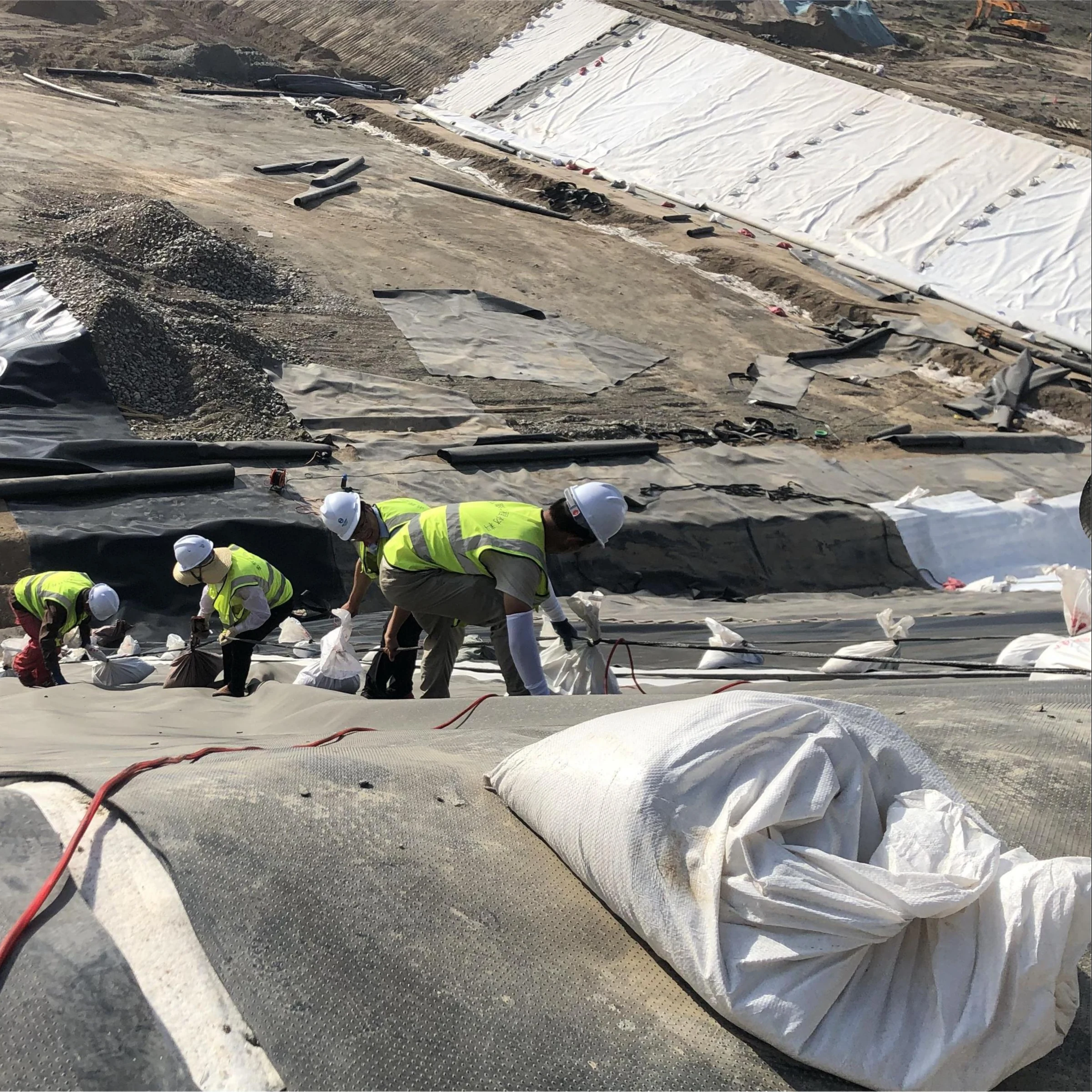
Sandbags or other approved ballast should be placed so they do not damage or contaminate the liner. Soil, loose aggregate, sharp metal, tires with exposed wire, or uncontrolled equipment should not be used as makeshift ballast.
Deployment should stop when wind conditions prevent safe control of the panels. A partially unrolled HDPE sheet can act like a sail and endanger personnel, damage completed seams, or pull material from an anchor trench.
Anchor the Geomembrane Correctly
Use Temporary Anchorage During Installation
Temporary anchorage stabilizes deployed panels before permanent terminations are completed.
Temporary measures may include:
- Sandbags.
- Approved ballast tubes.
- Temporary burial at designated locations.
- Controlled clamping at prepared structures.
- Sequenced placement into an open anchor trench.
Temporary anchorage must not puncture the geomembrane or interfere with later welding and inspection. Ballast should also be moved carefully so that dirt is not dragged into seam areas.
Build Anchor Trenches to the Approved Design
There is no single anchor trench dimension suitable for every landfill.
Required dimensions depend on factors such as:
- Slope length and inclination.
- Geomembrane surface type.
- Interface shear resistance.
- Construction loads.
- Thermal contraction.
- Wind uplift.
- Soil type and compaction.
- Liner system geometry.
- Distance from the slope crest.
- Long-term settlement.
- Project-specific safety factors.
The trench should be excavated, inspected, and accepted before geomembrane placement. Its corners should not create sharp bends that overstress the sheet.
Generic instructions such as “use a 0.6 m × 0.6 m trench” are not reliable design guidance. The engineer’s approved anchorage detail controls.
For design considerations, see Jinseed’s guide to geomembrane liner anchorage trench design.
Do Not Backfill the Anchor Trench Too Early
Premature backfilling can prevent the sheet from adjusting during thermal expansion and can conceal damaged material or incomplete seams.
Before permanent backfilling, the project team should confirm that:
- The correct panel is positioned in the trench.
- Required slack has been provided.
- Nearby seams are complete.
- Seam testing has been accepted.
- Termination details are approved.
- No bridging or sharp folds are present.
- The CQA representative has released the area.
Backfill should be placed and compacted without driving equipment directly over exposed geomembrane or pulling the sheet out of position.
Weld the HDPE Geomembrane
Perform Trial Welds Before Production Seaming
Trial welds are used to establish whether the selected equipment settings can produce an acceptable seam under the actual site conditions.
A new trial weld should be considered when there is a meaningful change in:
- Welding machine.
- Operator.
- Sheet thickness.
- Geomembrane formulation.
- Surface type.
- Ambient temperature.
- Sheet temperature.
- Wind.
- Humidity or condensation.
- Machine interruption.
- Shift or work period, as required by the CQA plan.
Trial weld material should be representative of the panels being installed. The trial seam is then cut into specimens and tested using the field tensiometer or other approved equipment.
The purpose is not to find one permanent machine temperature and use it for the entire project. The purpose is to verify that the complete combination of temperature, speed, pressure, operator technique, sheet condition, and weather can create an acceptable weld at that time.
ASTM D6392 identifies hot wedge, hot air, and extrusion processes and describes destructive peel and shear testing for nonreinforced geomembrane seams. (ASTM D6392)
Use Dual-Track Hot Wedge Welding for Accessible Production Seams
Dual-track hot wedge welding is commonly used for long, accessible HDPE field seams.
The welder creates two parallel fusion tracks separated by an unwelded air channel. This allows the seam continuity to be evaluated later using a pressurized air channel test.
Before the welder enters the overlap, the crew should verify that:
- The overlap is adequate for the machine and approved detail.
- Both sheet surfaces are clean and dry.
- The panels are correctly aligned.
- Wrinkles are controlled.
- No dirt, moisture, oil, grinding debris, or foreign material is trapped in the overlap.
- The machine has completed an accepted trial weld.
- The operator can maintain continuous movement.
- The seam identification has been assigned.
A clean seam area is critical. Welding over dust or moisture does not become acceptable simply because the machine completes the pass.
The operator should continuously observe machine travel, roller pressure, alignment, and the appearance of the completed seam. Stops, starts, fishmouths, wrinkles, burn marks, and visible discontinuities should be marked for inspection.
Reserve Extrusion Welding for Details and Repairs
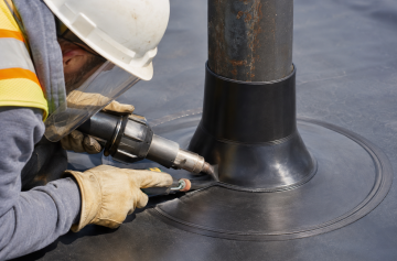
Extrusion welding is normally used where wedge welding is impractical, including:
- Repair patches.
- Pipe boots.
- Sump details.
- Short tie-in seams.
- T-connections.
- Corners.
- Mechanical attachment transitions.
- Destructive sample locations.
- Irregular geometry.
Extrusion weld areas generally require surface preparation. Oxidized or contaminated material is removed by controlled grinding immediately before welding, following the approved procedure.
Over-grinding can reduce sheet thickness and create a new weak area. Grinding too far in advance can also allow the prepared surface to become contaminated again.
The extrusion rod must be compatible with the geomembrane and maintained free from moisture and contamination. The technician should avoid abrupt starts, voids, excessive bead buildup, and sharp bead terminations.
Stop Welding When Conditions Are Unsuitable
Production welding should stop when:
- Rain, condensation, frost, or standing water is present.
- Wind prevents stable temperature control or sheet alignment.
- The sheet is contaminated.
- The machine cannot maintain its calibrated operating condition.
- Trial welds fail.
- Required testing equipment is unavailable.
- Lighting is insufficient for inspection.
- The subgrade or underlying layer has deteriorated.
- The sheet temperature is outside the approved procedure.
Continuing to weld in unsuitable conditions usually creates more rework than stopping and protecting the area.
Perform Geomembrane Seam QC Testing
Start With Continuous Visual Inspection
Visual inspection should be performed during welding and again after the seam has cooled.
Inspectors should look for:
- Misalignment.
- Unwelded sections.
- Burned or excessively thinned material.
- Fishmouths and wrinkles.
- Contaminated welds.
- Inconsistent extrusion bead shape.
- Voids.
- Excessive grinding.
- Damage adjacent to the seam.
- Uncontrolled seam intersections.
- Incomplete repairs.
- Unsealed test needle holes.
Visual inspection cannot prove seam continuity or strength, but it identifies conditions requiring immediate correction and determines whether the seam is ready for formal testing.
Air-Pressure Test Dual-Track Seams
ASTM D5820 covers nondestructive evaluation of parallel geomembrane seams separated by an unwelded air channel.
The basic procedure involves:
- Sealing both ends of the air channel.
- Inserting the approved pressure device.
- Pressurizing the channel to the project-specified value.
- Allowing pressure to stabilize where required.
- Monitoring pressure for the specified test period.
- Checking the opposite end to confirm that the full channel was tested.
- Recording the initial pressure, final pressure, duration, seam length, temperature, and result.
- Sealing and inspecting the needle hole.
The acceptance pressure, test duration, allowable pressure loss, and retest procedure must come from the project specification. They should not be copied from an unrelated project.
ASTM specifically states that air-channel testing evaluates seam continuity but does not replace destructive strength testing. (ASTM D5820)
Vacuum-Box Test Extrusion Welds and Accessible Repairs
ASTM D5641/D5641M covers vacuum-chamber evaluation of geomembrane seams, patches, and defects.
A typical test sequence includes:
- Cleaning the test area.
- Applying an approved bubble-forming solution.
- Positioning the vacuum chamber over the seam.
- Creating the specified vacuum.
- Observing the area through the transparent chamber.
- Marking any continuous bubble formation.
- Repairing identified defects.
- Retesting the repair.
The test is suitable only where the chamber can form an effective seal. Uneven corners, curved penetrations, thick bead transitions, or inaccessible areas may require another approved nondestructive method.
The current ASTM practice also identifies limitations on uneven surfaces, curved areas, thick seams, corners, and certain thin extensible geomembranes. (ASTM D5641/D5641M)
Test Destructive Seam Samples in Peel and Shear
Nondestructive testing checks continuity. Destructive testing evaluates seam strength and failure behavior.
Samples are removed from selected field seams at the locations and frequency required by the CQA plan. The sample is normally divided among:
- Installer field testing.
- CQA or independent laboratory testing.
- Archive or dispute-resolution storage.
ASTM D6392 provides the test procedure for peel and shear evaluation of nonreinforced geomembrane seams. GRI-GM19 provides seam strength and related acceptance values for thermally bonded polyolefin geomembranes.
The result should not be judged by peak strength alone. Inspectors should also review:
- Peel separation.
- Film tearing bond behavior.
- Shear elongation.
- Location of failure.
- Consistency among specimens.
- Whether both tracks of a dual-track seam were evaluated as required.
- Conformance with the approved specification.
If a destructive sample fails, the project procedure should define how the failing seam is bounded. This may involve taking additional samples on both sides of the failed location until acceptable limits are established, followed by repair or replacement of the affected seam length.
GRI-GM29 recommends evaluating field seam integrity through a progression of visual inspection, nondestructive testing, and destructive seam testing rather than relying on a single method. (Geosynthetic Institute, GRI-GM29)
Consider Electrical Leak Location Testing
Electrical leak location, or ELL, can identify holes in the installed geomembrane that may not be associated with field seams.
Possible defects include:
- Punctures caused during deployment.
- Damage beneath ballast.
- Tool drops.
- Holes created during geotextile placement.
- Damage from drainage aggregate.
- Unrecorded cuts or temporary attachments.
- Defective repairs.
ASTM D7007 covers electrical methods for locating leaks in geomembranes covered with water or earthen materials. Other ASTM methods apply to exposed geomembranes or conductive-backed systems.
ELL is not a replacement for seam testing or CQA observation. It is an additional whole-area integrity check. Its effectiveness depends on liner configuration, electrical isolation, underlying conductivity, cover condition, equipment, calibration, and technician competence. (ASTM D7007)
| QC method | Primary purpose | Typical application | Does it verify seam strength? |
|---|---|---|---|
| Visual inspection | Identify visible workmanship defects | Panels, seams, repairs and details | No |
| Air-channel test | Check continuity of dual-track seams | Hot wedge seams | No |
| Vacuum-box test | Locate discontinuities by bubble emission | Extrusion seams and accessible repairs | No |
| Peel and shear testing | Evaluate seam strength and failure behavior | Destructive field samples | Yes |
| Electrical leak location | Locate holes across installed liner area | Exposed or covered geomembrane, depending on method | No |
Repair Defects and Retest the Area
Mark Every Defect With a Unique Number
Defects should be marked immediately and entered in the repair log.
The record should identify:
- Repair number.
- Panel number.
- Seam number where applicable.
- Location or coordinates.
- Type of defect.
- Suspected cause.
- Repair method.
- Technician.
- Date and time.
- Nondestructive test method.
- Test result.
- CQA acceptance.
Numbered repair records prevent marked defects from being forgotten when the crew moves to another area.
Select the Repair Method Based on Defect Geometry
Common repair methods include:
- Extrusion-welded patch.
- Cap strip.
- Removal and replacement of a seam section.
- Extrusion bead repair.
- Replacement of an entire damaged panel area.
- Approved mechanical termination at structures.
Patches should be large enough to extend beyond the damaged area and should use rounded corners to reduce stress concentration.
A patch should not be used to conceal an unknown defect. The damaged area must first be inspected so that the repair covers the full affected zone.
Retest Every Completed Repair
A repair is not complete when the welding technician leaves the area.
It is complete only after:
- The weld has cooled.
- The repair has been visually inspected.
- The specified nondestructive test has passed.
- The repair log has been completed.
- The CQA representative has accepted the repair.
Where a defect is discovered after placement of a protective layer, the repair procedure may require careful removal and replacement of the overlying materials, followed by additional leak location testing.
Protect the Completed Landfill Geomembrane
Install the Protective Geotextile Carefully
A nonwoven geotextile is commonly placed over the geomembrane to reduce puncture risk from drainage aggregate, pipe bedding, or operational layers.
The required geotextile properties must be selected by engineering evaluation. Mass per unit area alone is not enough to determine whether a product provides adequate puncture protection.
During installation:
- Do not drag contaminated geotextile across the geomembrane.
- Remove wire, staples, broken pallets, and packaging debris.
- Use approved seams or overlaps.
- Prevent folds that could disturb the drainage layer.
- Maintain the designed relationship around pipes and sumps.
- Inspect the geomembrane immediately before covering.
- Record the area released for cover placement.
Jinseed supplies PET nonwoven geotextile for protection, filtration, separation, and drainage applications. The selected grade should be confirmed against project-specific puncture protection and hydraulic requirements.
Place Drainage Aggregate Without Direct Impact
Drainage aggregate should not be dumped from excessive height directly onto the geomembrane or thin protection layer.
The approved placement method should define:
- Minimum protection thickness before equipment access.
- Maximum equipment ground pressure.
- Acceptable aggregate gradation and angularity.
- Maximum drop height.
- Spreading direction.
- Turning and braking restrictions.
- Pipe-placement sequence.
- Required spotters and CQA observation.
Equipment should push material over previously placed cover rather than drive directly on the exposed liner system.
Coordinate Pipes, Sumps, and Penetrations
Sump areas concentrate multiple liner details and are therefore especially sensitive.
The sequence should allow:
- Smooth geomembrane placement.
- Access for welding.
- Access for nondestructive testing.
- Installation of pipe boots and attachments.
- Surveying.
- Leak location testing where specified.
- Placement of protection layers without excessive bridging.
Changes to pipe elevations or sump geometry should be reviewed by the design engineer before the liner is cut.
Prepare Complete CQA and Handover Records
Maintain Daily Installation Records
Daily reports should normally include:
- Date and work area.
- Weather and sheet temperature observations.
- Installer personnel and equipment.
- Panels deployed.
- Roll-to-panel traceability.
- Seams completed.
- Trial weld results.
- Nondestructive tests.
- Destructive samples.
- Repairs.
- Delays and stop-work conditions.
- Subgrade acceptance areas.
- Cover placement.
- Nonconformance reports.
- Instructions issued by the engineer.
- Photographs.
Records should be completed during the work rather than reconstructed several days later.
Produce an As-Built Panel and Seam Map
The as-built drawing should show:
- Final panel boundaries.
- Panel identification.
- Roll identification.
- Seam numbers.
- Destructive sample locations.
- Repair locations.
- Penetrations.
- Sumps.
- Anchor trenches.
- Mechanical attachments.
- Tie-ins to previous construction phases.
- Surveyed coordinates or reference grids.
- Areas covered before final inspection, if any.
The map should reflect the actual installation, not simply repeat the original panel layout.
Assemble the Final Acceptance Package
A complete landfill geomembrane acceptance package may include:
- Approved material submittals.
- Manufacturer QC certificates.
- Delivery inspection records.
- Subgrade acceptance forms.
- Panel deployment logs.
- Trial seam records.
- Production seam logs.
- Air-pressure test records.
- Vacuum-box test records.
- Destructive test reports.
- Repair logs.
- Electrical leak location report where required.
- Nonconformance reports and resolutions.
- Survey information.
- As-built drawings.
- Photographs.
- CQA certification or final report required by the permit.
EPA guidance emphasizes that CQA documentation should demonstrate that the liner was built in accordance with the approved design and that inspection and testing requirements were implemented. (U.S. EPA)
Avoid Common Landfill Geomembrane Installation Mistakes
Using Fixed Welding Settings Throughout the Project
Welding temperature and speed are not universal material constants. They are machine settings influenced by sheet thickness, surface temperature, wind, equipment condition, operator technique, and other site factors.
Trial weld acceptance should control production welding.
Copying Anchor Trench Dimensions From Another Project
An anchor trench must resist the forces calculated for the actual slope and liner system. Copying a standard-looking trench detail without design verification can create either inadequate anchorage or unnecessary excavation.
Welding Over Dust, Moisture, or Ground Material
A seam can look continuous from above while containing contamination within the bonded area. Cleaning must occur immediately before welding, not only at the beginning of the shift.
Allowing Excessive Wrinkles to Become Trapped
Some temporary thermal wrinkling is unavoidable, but large wrinkles should not be folded into seams, trapped beneath drainage layers, or forced into sumps.
Panel positioning, welding time, cover placement, and temperature conditions should be coordinated.
Covering the Liner Before Testing Is Complete
Once geotextile, drainage aggregate, and pipes are installed, access to the geomembrane becomes difficult and expensive.
No area should be covered until required inspection, seam testing, repair testing, documentation, and CQA release have been completed.
Treating Nondestructive Testing as a Strength Test
Air pressure and vacuum testing identify discontinuities. They do not establish peel strength, shear strength, or acceptable failure mode.
Destructive testing remains necessary where required by the project CQA plan.
Treating the Supplier as the Project Designer
A geomembrane manufacturer can provide material specifications, roll dimensions, certificates, installation recommendations, and technical data. The manufacturer should not replace the project engineer’s responsibility for landfill design, slope stability, anchorage, interface shear, drainage, settlement, or regulatory approval.
Landfill Base Liner Installation Checklist
Before Deployment
Confirm that:
- Approved drawings and CQA documents are available.
- Geomembrane rolls match the purchase specification.
- Roll certificates and identification are traceable.
- Storage and lifting methods are suitable.
- The subgrade, clay liner, or GCL has been accepted.
- Anchor trenches and details match the drawings.
- Survey control is available.
- Weather conditions are suitable.
- The panel layout has been reviewed.
During Deployment and Welding
Confirm that:
- Panel numbers and roll numbers are recorded.
- The sheet is not dragged or punctured.
- Wind ballast is non-damaging.
- Weld zones are clean and dry.
- Trial welds have passed.
- Wedge welds and extrusion welds are used in suitable locations.
- Seams remain accessible for testing.
- Daily records are current.
- Defects are marked immediately.
Before Cover Placement
Confirm that:
- Visual inspection is complete.
- Dual-track seams have passed air-channel testing.
- Extrusion seams and patches have passed the specified test.
- Destructive samples have been accepted.
- Failed seams have been bounded and repaired.
- Every repair has been retested.
- Electrical leak location has been completed where specified.
- The as-built map has been updated.
- The CQA representative has released the area.
- The protective geotextile and cover-placement method are approved.
Final Installation Guidance
A successful HDPE landfill base liner installation depends on controlled sequencing rather than one welding parameter or one final leak test.
The strongest project controls are:
- Design-specific material and anchorage requirements.
- Formal acceptance of the underlying layer.
- Traceable panel deployment.
- Trial-weld-based machine calibration.
- Dual-track welding for accessible production seams.
- Extrusion welding for details and repairs.
- Visual, nondestructive, destructive, and electrical testing where applicable.
- Complete repair and retest records.
- Controlled placement of protection and drainage layers.
- Independent CQA documentation.
Jinseed supplies smooth and textured HDPE geomembrane, nonwoven geotextile, and other geosynthetic materials for landfill liner systems. Before requesting a quotation, buyers should prepare the project thickness, surface type, roll dimensions, required standard, total area, destination, and approved technical specification.
Material selection should always be reviewed together with the landfill design, site conditions, interface shear requirements, installation method, and local regulatory obligations.
Sources and Technical References
- Electronic Code of Federal Regulations — 40 CFR §258.40, Design Criteria
- U.S. EPA — Quality Assurance and Quality Control for Waste Containment Facilities
- U.S. EPA — Inspection Techniques for the Fabrication of Geomembrane Field Seams
- Geosynthetic Institute — GRI-GM13, HDPE Geomembrane Specification
- Geosynthetic Institute — GRI-GM19a, Seam Strength and Related Properties
- Geosynthetic Institute — GRI-GM29, Integrity Evaluation of Geomembrane Field Seams
- ASTM International — ASTM D5820, Pressurized Air Channel Evaluation of Dual-Seamed Geomembranes
- ASTM International — ASTM D5641/D5641M-25, Geomembrane Seam Evaluation by Vacuum Chamber
- ASTM International — ASTM D6392-25, Integrity of Nonreinforced Geomembrane Seams
- ASTM International — ASTM D7007-24, Electrical Methods for Locating Leaks in Covered Geomembranes
- International Geosynthetics Society — Geosynthetic Barriers in Waste Containment Facilities