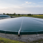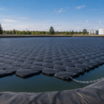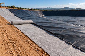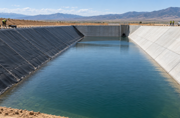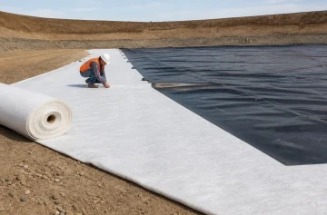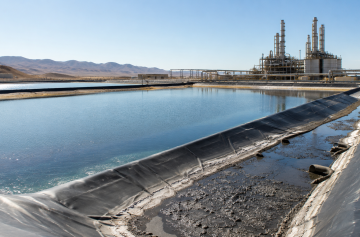


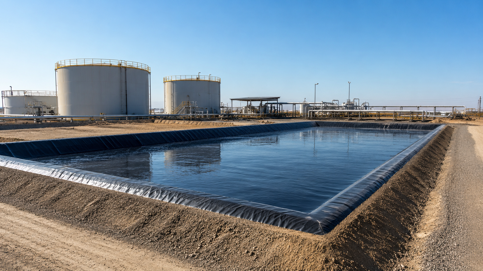
Once an oil or gas storage tank ruptures and leaks, it will directly threaten soil and groundwater. According to EPA SPCC regulations, oil storage facilities must be equipped with a secondary containment system—capturing and retaining oil products within the levee area before they can spread into the environment. A properly designed secondary containment system can reduce the probability of environmental pollution caused by leaks by more than 85%.
Hydrocarbon Resistance
Oil Contact Risk
The oil contact risks faced by the secondary containment layer of oil and gas pools mainly come from three dimensions: static immersion, dynamic permeation, and chemical corrosion. Static immersion risk occurs during the period of oil accumulation in the containment area, where the containment liner is in prolonged contact with high-concentration hydrocarbon liquids, causing the material surface to soften, swell, or even delaminate and peel off. Dynamic permeation risk is caused by the capillary adsorption effect of oil products at the geomembrane interface—light oils (such as gasoline and diesel) can penetrate into the inner layer along the micropore structure of the geomembrane due to their low viscosity and small surface tension, contaminating the subsoil.
Chemical corrosion risk shows significant oil-type dependency: phenolic compounds in acidic crude oil have moderate corrosivity to HDPE; biodiesel containing alcohols will accelerate plasticizer leaching from PVC film; fuel oil with high aromatic content operating above 40℃ will have an erosion rate on ordinary polyethylene 3-5 times higher than that under normal temperature conditions. Additionally, dissolved water in oil products (when salinity exceeds 5,000mg/L) will form a weakly acidic environment at the interface between the geomembrane and concrete base, promoting localized electrochemical corrosion. It should be noted that accidental oil contact with oil and gas pool containment layers is often accompanied by a sudden temperature rise—when hot oil (≥60℃) leaks into the containment area, the interlayer shear stress caused by the difference in thermal expansion coefficients between the containment layer material and the base can cause delamination between the liner and base.
Liner Material Selection
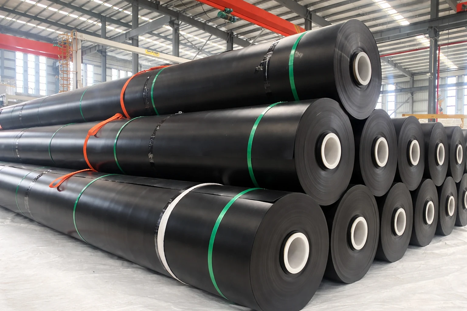
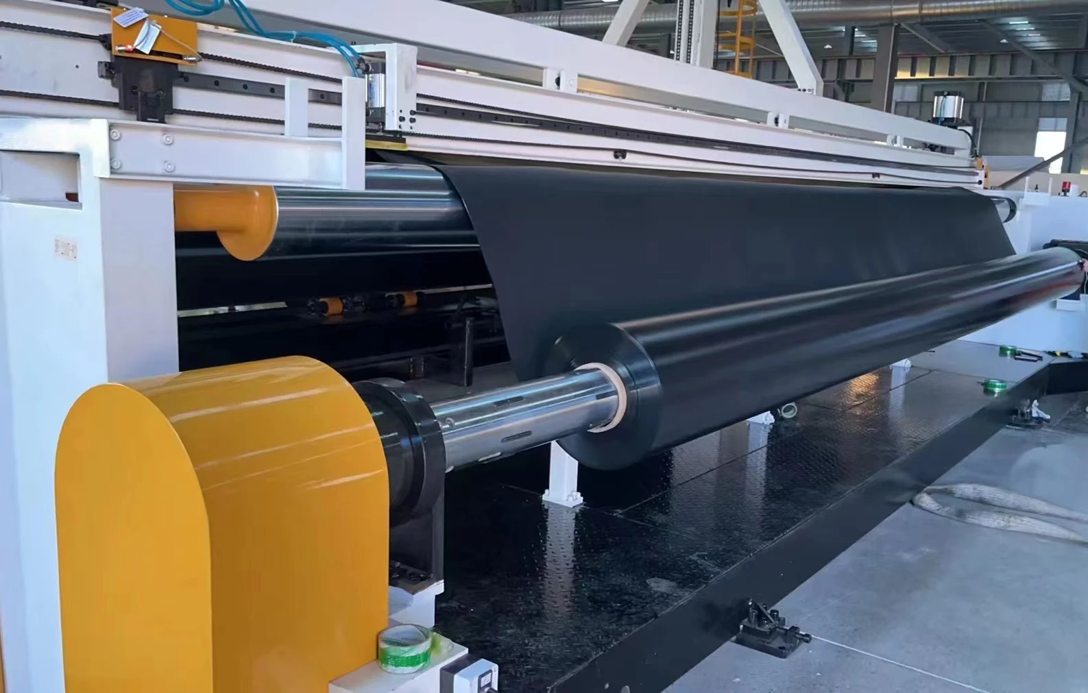
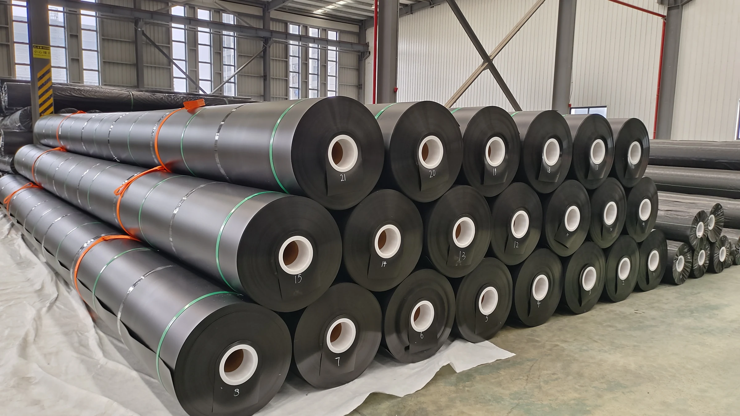
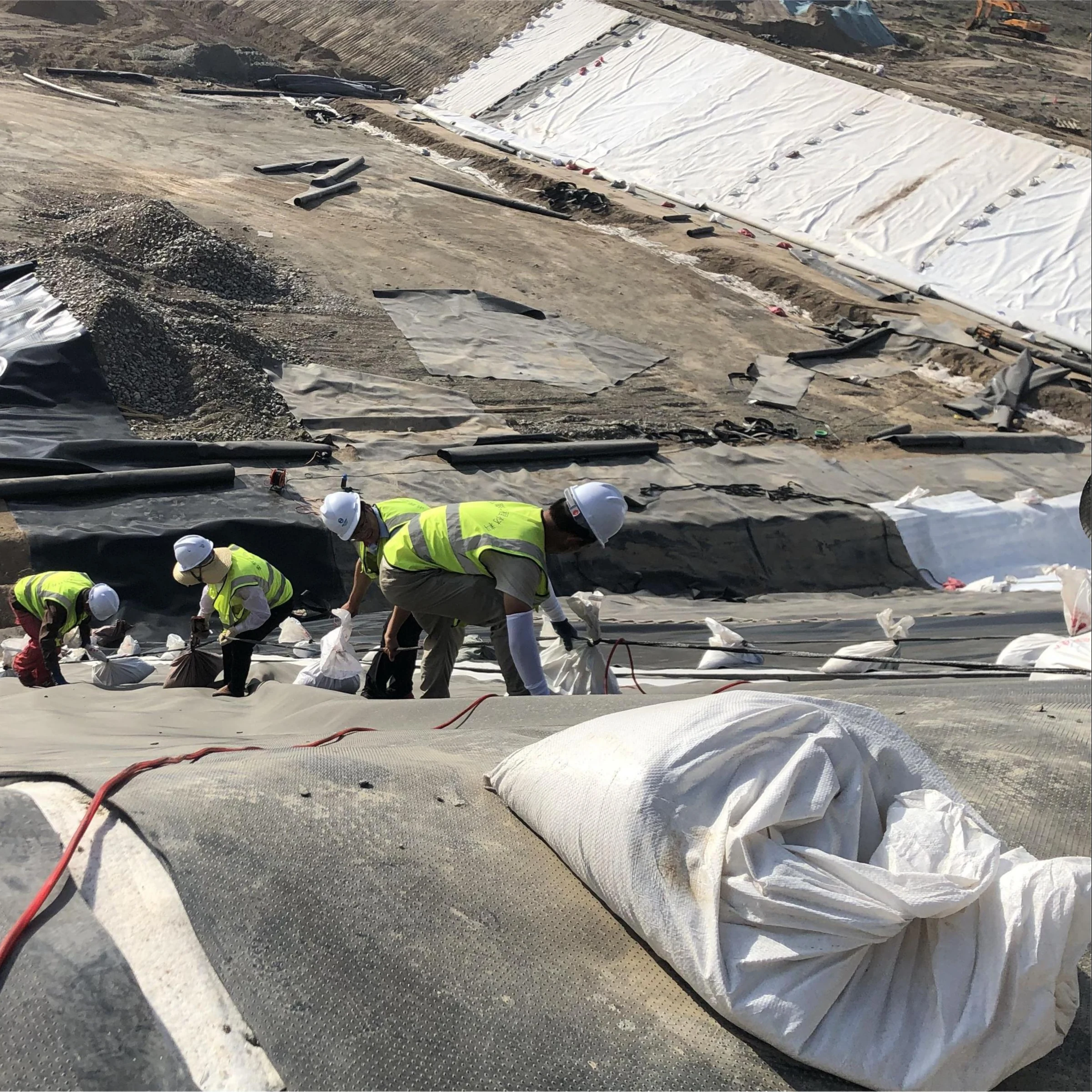
The liner materials for secondary containment layers must achieve a balance among hydrocarbon resistance, mechanical strength, and construction feasibility. The performance differences among the three mainstream containment liner materials on the market under oil contact conditions are significant:
| Material | Hydrocarbon Resistance | Tensile Strength | Temperature Range | Suitable Oil Products |
| HDPE (smooth) | Excellent | ≥20MPa | -40℃ to +80℃ | Crude oil, diesel, fuel oil |
| HDPE (textured) | Excellent | ≥15MPa | -40℃ to +80℃ | Crude oil, diesel, fuel oil |
| PP (polypropylene) | Good (poor with aromatics) | ≥25MPa | 0℃ to +100℃ | Diesel, engine oil, hydraulic oil |
| PVC (flexible) | Moderate (poor aromatic resistance) | ≥12MPa | -20℃ to +60℃ | Diesel, engine oil |
| FPP (fluoroalloy membrane) | Excellent | ≥18MPa | -30℃ to +120℃ | All oil types |
For crude oil and fuel oil storage facilities, **2.0mm HDPE** is recommended as the primary containment liner material, with a permeability coefficient for hydrocarbon molecules lower than 1×10⁻¹² cm³·cm/cm²·s·Pa, and it can withstand the high-concentration benzene series compounds commonly found in crude oil. For facilities storing high-aromatic-content fuel oil (benzene content >5%) or biodiesel, upgrading to FPP (fluoroalloy-modified polypropylene) liner is recommended. The fluoroalloy surface layer has a barrier efficiency for aromatic molecules approximately more than 10 times that of HDPE, but the material cost is approximately 4-6 times that of HDPE, and selection should be based on a comprehensive evaluation of leak probability and environmental sensitivity.
PVC liner in oil and gas pool containment is only recommended for light diesel storage, and a concrete protective layer must be installed above the liner to prevent membrane deformation under compression. When selecting liner thickness, the influence of oil temperature on material performance must also be considered: for hot oil conditions (≥50℃), the nominal thickness of HDPE should be increased one grade to 2.5mm, and a thermal insulation buffer layer should be installed below the liner. For marine-deposited crude oil storage facilities (sulfur content >0.5%), the liner must be treated with anti-H₂S coating.
Seam Leakage Inspection
Levee Construction
Levee Height Diagram
The determination of levee height is the core calculation problem in the design of a secondary containment system. The U.S. SPCC regulations stipulate that the effective volume of the levee must be ≥110% of the maximum single container volume of the protected object; if the containment area houses multiple tanks, the levee must cover 100% of the largest single tank volume plus 10% of the total volume of the remaining tanks. The design height of the levee also needs to reserve an additional clearance of no less than 300mm above the calculated volume to accommodate rainwater accumulated during heavy rain and the volume increase due to thermal expansion of the oil under extreme operating conditions.
For a compartmentalized containment area with internal partition walls, the volume of each compartment shall independently satisfy the above requirements. The calculation of levee height must consider the bearing capacity of the foundation – when constructing a levee on soft soil foundation (bearing capacity < 80 kPa), if the design height exceeds 2.0 m, a finite element analysis must be performed to verify the differential settlement of the foundation, ensuring that the levee inclination caused by non‑uniform settlement does not exceed H/100 (where H is the levee height).
The construction tolerance for levee height is ±20 mm, and the deviation of the top surface flatness shall not exceed 10 mm per 2 m. In typical petrochemical parks, the levee height for single‑tank areas is generally between 1.0–1.8 m, while for double‑tank or larger contiguous containment areas the levee height is usually 1.2–2.5 m. The top of the levee must be equipped with collision‑proof guardrails (height ≥1.1 m), with guardrail post spacing no greater than 2.0 m, to prevent operational vehicles from accidentally colliding with the levee slope. The oil‑facing side (inner slope) of the levee is recommended to be covered with linked hinge‑type slope protection mats or three‑dimensional vegetation geogrid, to reduce the erosive impact of oil wave action on the slope surface and provide a safe walking surface for inspection personnel.
Slope and Bottom
The inner slope gradient of the levee is a key parameter affecting the oil retention capacity and structural stability of the containment area. The SPCC guidelines recommend a levee inner slope ratio of 1:2 (vertical:horizontal, i.e., 26.6°) to 1:3 (18.4°). A slope that is too steep (steeper than 1:1.5) will generate larger lateral thrust under the static pressure of the oil, increasing the risk of levee sliding; a slope that is too gentle (gentler than 1:4) will occupy too much site area. The top of the levee should be provided with an operational platform at least 600 mm wide to allow inspection personnel passage and placement of emergency equipment.
The bottom design of the containment area must ensure that the liquid does not create local accumulation during oil retention, forming a “dead zone”. The longitudinal bottom slope is recommended to be 1:100 to 1:200 (longitudinal direction referring to the main direction of oil leakage), and the transverse slope is 1:100 to 1:150, sloping toward the oil collection point or oil collection trench. The intersection of the bottom with the levee (the reentrant corner area) should be provided with a rounded transition, with a radius of no less than 300 mm, to prevent oil from forming a stagnant dead zone at this location.
After compaction of the subsoil base, the compaction degree shall reach K ≥95% (light compaction standard), and the permeability coefficient shall be less than 1×10⁻⁷ cm/s, to ensure that the base itself has a secondary containment function – even if the containment liner is partially damaged, the base can still retain the leaked oil for a sufficient time to allow emergency response. At the external corner where the levee meets the base slab (the external corner), a waterstop strip (made of neoprene rubber or PVC material) should be installed embedded in the concrete haunch, with a width of no less than 300 mm, to seal the interface gap between the liner and the levee structure. The oil collection trench should preferably be a cast‑in‑place concrete trench, with the inner walls coated with a hydrocarbon‑resistant anti‑corrosion coating, the trench width no less than 400 mm, and the trench depth determined based on the calculated rainwater volume but not shallower than 200 mm.
Soil Compaction Inspection
Oil Spill Prevention
Drainage Valve Control
The internal drainage system of the protected area is a key control node for preventing rainwater accumulation from submerging the protected area, and also for blocking the discharge of oil products when an oil spill occurs. The drainage valve in the protected area should adopt **normally closed electric ball valve** or **pneumatic butterfly valve**, and be equipped with a manual emergency operation mechanism. Under normal operating conditions, the drainage valve remains closed, and the rainwater accumulated in the protected area is gravity-discharged to the wastewater treatment system through a drainage well with a water seal structure; once the oil spill alarm is triggered, the control system should automatically close the drainage valve within 30 seconds to cut off the oil discharge channel.
The selection of drainage valve must meet the following technical requirements: the valve body material should be stainless steel 316L or chloroprene rubber lining to withstand oil immersion corrosion; the valve closing torque should have a safety margin of no less than 30% to cope with the increased opening/closing resistance after the valve seat is covered with oil fouling; the protection level of electric/pneumatic actuator should be no less than IP67. An **oil spill monitoring device** (capacitance or ultrasonic level sensor) must be installed at the first inspection well outside the protected area. When the oil content in the discharged liquid exceeds 15mg/L, it sends an oil spill alarm to the control system and locks the drainage valve. The control logic should follow the “oil alarm takes priority over water alarm” principle – that is, as long as the oil spill sensor alarms, regardless of the liquid level, the drainage valve shall not be opened.
Rainwater Treatment
Rainwater management in the protected area is the most frequent operation in daily maintenance. Large amounts of rainwater accumulating in the protected area will dilute the oil product concentration, accelerate corrosion, and create hydrostatic pressure on the embankment structure. If rainwater is not discharged in time, the protected area may be in a semi-submerged state during the rainy season, causing the protective lining to be immersed in oil-water mixture for a long time, accelerating aging and failure.
The standard practice is: install an automatic rainwater drainage system at the bottom of the protected area, with ultrasonic level gauge linked to the drainage valve, automatically detecting the liquid accumulation height in the area once per hour. When the liquid level exceeds 200mm and the oil spill sensor has not alarmed, the control system automatically opens the drainage valve for rainwater drainage; if the liquid level reaches 300mm and no significant decrease is observed, a “drainage abnormality” alarm is sent, prompting maintenance personnel to conduct on-site inspection. When the oil spill sensor alarms, the drainage valve is immediately locked, and the liquid in the area shall not be discharged, and automatic drainage function can only be restored after the professional team completes the oil spill cleanup.
A rainwater intercepting ditch should be set at the top of the embankment to divert the water collected at the top of the embankment outside the protected area, preventing top rainwater from flowing directly into the area and increasing the drainage burden. The intercepting ditch should adopt reinforced concrete structure, with ditch width no less than 300mm and ditch wall thickness no less than 150mm. In cold winter regions, anti-freezing measures for drainage pipes must also be considered – in areas where the monthly average minimum temperature is below 0°C, drainage pipes should be buried below the permafrost layer (usually depth ≥1.2m), or electric tracing tape should be wrapped on the outer wall of exposed pipes with a temperature monitoring system to prevent valve jamming caused by water accumulation and freezing.
Emergency Oil Spill Response Procedures
When the oil spill sensor alarms or an oil spill is confirmed manually, the following standardized procedures must be followed for emergency response:
- Step 1: Trigger oil spill alarm, close all non-emergency drainage valves, and cut off the discharge channel. Set up warning signs in the control room and oil spill area, notify the emergency command center
- Step 2: Assess the oil spill volume and spread range. Use portable PID detector to delimit three-level control areas – core area (within 5m), buffer area, monitoring area
- Step 3: Deploy inflatable or solid floating booms at the inner toe of the embankment to slow down the oil climbing, boom length should cover 1.2 times the spread width
- Step 4: Oil spill recovery. Use explosion-proof vacuum oil suction equipment (≥500L/min) for recovery, waste oil sent to hazardous waste temporary storage area, wastewater treated to meet standards before discharge
- Step 5: Contaminated soil treatment. Replace contaminated soil in bottom and corner areas, depth determined according to oil product type (light 300-500mm, heavy 500-800mm), backfill soil must pass inspection
- Step 6: Recovery and summary. Conduct comprehensive inspection of protective lining, repair damaged areas. Complete oil spill accident report (time, location, product type, quantity, process, lessons learned), archive for no less than 20 years
The design quality of the secondary protection system of the oil and gas tank directly determines the environmental impact consequences when a leak occurs. The correct selection of hydrocarbon-resistant lining is the basis of protection performance, the compaction control of embankment construction is the prerequisite for structural safety, and the reliable linkage of drainage valves and the institutionalization of oil spill emergency procedures are the last line of defense to control the accident impact within the embankment. The three aspects are all indispensable, and any design defects or construction negligence in any one area may be amplified in actual leak incidents, causing irretrievable environmental damage.
For facilities already in operation, it is recommended to conduct a comprehensive technical assessment of the secondary protection system every three years, including: lining aging ultrasonic thickness measurement, joint air tightness retest, valve linkage function test, and oil spill emergency plan tabletop exercise. The assessment results should be used as a required attachment for facility life extension permit approval.