Before installation, make sure the subgrade is compacted to at least 90%, with surface flatness controlled within 1 cm. Welding temperature should be kept between 260–320°C, welding speed at 2–3 m/min, and overlap width at 100–150 mm. For air-pressure testing, maintain 0.2–0.3 MPa for 5 minutes.

Welding Techniques
Dual-Track Thermal Fusion Welding
This type of dual-track wedge welder weighs about 15–25 kg and uses a 150 mm copper heating wedge. Once the machine is powered on, the copper wedge is inserted between the upper and lower sheets. It heats the contact surfaces to 350–420°C, which is hot enough to soften the HDPE surface into a tacky molten state without scorching it.
- Machine travel speed: 1.5–2.5 m/min
- Copper wedge preheating time: at least 10 minutes
- Overlap width: 100–120 mm
- Membrane surface condition: no water or mud within 300 mm on either side of the seam
As the machine moves forward, the pressure rollers immediately follow behind. For 1.5 mm sheet, the rollers should apply about 600 N of force. For 2.0 mm sheet, the pressure should be increased to 850 N. This pressure forces the molten polymer molecules together so that, once cooled, the two sheets become one continuous body.
A properly made seam will show a small bead of squeezed-out material along the edge, typically 1–2 mm wide. This indicates that the weld penetration has reached about one-third of the sheet thickness, which is a sign of an acceptable weld. Dual-track welding forms two solid weld tracks, each 15 mm wide, with a 10 mm air channel between them for later pressure testing.
- Morning work: dew is common, so the sheet must be wiped dry with cotton cloth
- Midday work: under strong sun, machine speed should be about 15% faster than in the morning
- Wind warning: stop work when wind speed exceeds 24 km/h, to prevent temperature-control failure
- Avoid sand contamination: sand in the seam can reduce strength by more than 10%
Before starting work each day, a 1-meter trial weld must be made on scrap material at the site. After welding, it should be cut into 25 mm strips and pulled with a tensile tester. The day’s work may begin only if the sheet itself tears first and the weld remains completely intact.
- Sample width: standard 25 mm strip
- Tensile requirement: 1.5 mm sheet must withstand 17.5 N/mm
- Testing frequency: one sample sent to the lab every 150 meters of installed seam
- Acceptance criterion: weld strength must reach at least 90% of the parent material strength
After welding, insert a needle into the central air channel and inflate it to 30 psi. Watch the gauge for 5 minutes. If the pressure drop does not exceed 2 psi, the seam—possibly hundreds of meters long—passes inspection. If air leaks are found, apply soapy water to locate bubbles. Even pinhole leaks must be repaired.
- Inflation pressure: about 207 kPa
- Hold time: 300 seconds
- Allowable variation: within 10%
- Closure method: the needle hole must be sealed with a hot-air gun, and the repair patch must be at least 75 mm in diameter
Extrusion Welding
A handheld extrusion welder usually weighs 5–8 kg and uses an internal screw to melt 3 mm or 4 mm HDPE welding rod. This equipment is mainly used in areas the dual-track machine cannot reach, such as around pipe penetrations, inside and outside corners, and repair patches.
Before pulling the trigger, the operator must grind the seam area with a handheld grinder fitted with 60-grit or 80-grit abrasive. The goal is to remove about 0.01 mm of oxidized surface layer and expose fresh polyethylene. The grinding marks should run perpendicular to the seam direction, and the prepared area must extend 10–15 mm beyond the final weld edge.
- Welding output: 1.5–3.5 kg/hour
- Welding rod material: must match the membrane batch and density
- Maximum grinding depth: no more than 10% of sheet thickness
- Welding rod storage: when ambient temperature is below 10°C, rods must be kept in a constant-temperature box
Different PTFE welding shoes can be fitted to the front of the extrusion gun. As the molten material is extruded, the shoe preheats the membrane surface. Preheat air temperature is typically set to 240–280°C, so the parent material reaches a lightly molten state. The molten plastic itself, at around 210°C, is then pressed into the joint, allowing the molecules to recombine under pressure.
The finished weld bead is usually 20–40 mm wide and about 2–4 mm thick. A sound weld should have a smooth surface with no pores or black burned spots. The edges should show a uniform ripple pattern, which reflects a steady hand movement and consistent travel rhythm.
T-joints where three sheets meet require more careful treatment. The operator must first trim the square edge of the top sheet into a 45-degree bevel, then grind away all raised areas within 150 mm around the joint. This eliminates the physical step and prevents hollow leak points from forming as the welding shoe passes over it.
- Welding shoe angle: 45–60 degrees relative to the sheet surface
- Preheat nozzle distance: 5–10 mm above the sheet
- Joint overlap length: at least 150 mm
- Shutdown procedure: if the machine is stopped for more than 2 minutes, the residual material in the nozzle must be cleaned out
Fine airborne dust can easily create false welds during extrusion welding. On exposed sites with wind speeds above 20 km/h, a wind shield must be set up. If moisture remains on the sheet surface, the preheating air will turn it into bubbles trapped inside the weld bead, reducing strength by more than 30%. After each seam is completed, it must be allowed to cool naturally to below 40°C before being moved.
For pipe penetrations, a specially fabricated pipe boot is required. The weld between the base ring and the vertical sleeve must use double extrusion welding, with the overlap of the weld beads measuring at least 50 mm. When grinding around the outer edge of the ring, the pattern should radiate outward so the molten material can fully cover the cut edges of the membrane.
- Cooling: never force-cool with sprayed water
- Patch shape: must be circular or a rectangle with rounded corners
- Patch size: edges must extend 100–150 mm beyond the damaged area
- Temporary fixing: use a hot-air tack welder; adhesive is strictly prohibited
Because extrusion welds do not contain an air channel, they must be tested with a vacuum box. The inspector applies a 1:10 soap solution over the seam, then places a transparent vacuum box over it. A vacuum pump is used to reduce pressure inside the box to -35 kPa to -55 kPa and hold it there for 15 seconds.
If the soap film forms expanding bubbles, the weld contains pinholes. For certain special seam shapes, spark testing may also be used. In such cases, a fine copper wire is embedded along the seam edge before welding, and once the seam is complete, a high-voltage pulse detector is moved along the weld.
- Vacuum box standard: -5 psi (about 35 kPa)
- Overlap for each test placement: 75 mm
- Testing environment: adequate lighting is required to detect fine bubbles
- Spark test voltage: 15–30 kV, depending on membrane thickness
Destructive testing also applies to extrusion welds. At patches or long extrusion seams, one set of test samples must be cut every 150 meters. On the site tensile tester, a 25 mm wide strip must undergo peel testing. For 2.0 mm HDPE membrane, extrusion weld peel strength must reach at least 120 lb/in (21 N/mm).
If the weld peels completely off the parent sheet, it indicates inadequate grinding or insufficient preheat temperature. In that case, all seams completed by that operator on the same day must either be covered with a new extrusion bead or reground and repaired with larger patches. All inspection records must match the identification number printed beside the seam.
- On-site tensile speed: 50 mm/min
- Number of strips: 5 peel and 5 shear specimens
- Acceptance mark: FTB (Film Tear Bond—the parent sheet fails first)
- Weld bead reinforcement: not lower than the parent sheet thickness and not higher than 5 mm
Daily construction records should also include ambient humidity. When humidity exceeds 80%, extrusion weld peel strength often fluctuates by about 15%. Operators must recalibrate extrusion temperature every 4 hours to keep the molten zone depth consistently between 20% and 30% of the membrane thickness.
On slopes steeper than 1:3, extrusion welding should proceed from the bottom upward. This allows gravity to assist compaction under the welding shoe. The operator must secure their body with a safety rope and maintain steady hand pressure between 20 N and 40 N to prevent uneven weld thickness.
- Slope welding direction: bottom to top
- Constant pressure range: 2–4 kgf
- Overlap at weld start: overlap the previous seam by 50 mm
- Waste removal: molten residue on both sides of the seam must be cleaned off before cooling
Essential Tools
Welding Equipment
The dual-track hot wedge welder uses an electrically heated plate made from aluminum alloy. The plate temperature is typically set between 320°C and 420°C. Different temperatures are used for 1.5 mm and 2.0 mm sheets. The plate travels between the overlapped sheets and melts the contact surfaces.
The pressure rollers then apply force in the range of 800–1200 N. The molten plastic is pressed together and, once cooled, becomes two 10 mm wide weld tracks. A 10 mm air channel is left in the middle for inflation testing.
The machine travels across the membrane at 1.5–3.5 m/min. Operators adjust the speed according to ambient heat. If it moves too slowly, the sheet will burn through; if it moves too quickly, the sheets will not fuse properly.
- Material: high-conductivity aluminum alloy or stainless steel
- Pressure: 800–1200 N
- Weld seam: two 10 mm tracks
- Air channel: 10 mm in the middle
- Speed: 1.5–3.5 m/min
The machine above is used for long, continuous seams. For corners, small penetrations, and places it cannot reach, a handheld extrusion welder is used instead. Inside the machine, a screw feeds and melts 3 mm or 4 mm welding rod. Hot air at 260–300°C blows from the front nozzle, drying the membrane surface and preheating the edges.
The molten material is extruded at 2.0–4.0 kg/hour and deposited over the overlap between the two sheets. The welder must be held at about a 45-degree angle. Only when the flow is full and steady will the edges seal properly.
After welding, the bead is typically 20–30 mm wide. At the center, the bead thickness should be about 1.5 times the membrane thickness. It is used for pipe penetrations, corners, and any confined area too small for the larger machine.
- Rod diameter: 3 mm or 4 mm
- Output: 2.0–4.0 kg/hour
- Air temperature: 260–300°C
- Power: at least 1100 W
- Material temperature: 230–260°C
These machines draw significant power, so they must be connected to a 5 kW generator. Unstable voltage will cause temperature fluctuations, which must stay within 5%. If the power cable runs as long as 50 meters, it must have a cross-section of at least 4 mm².
For thin sheets below 0.5 mm, a single-track hot-air welder may be used. It has no heating wedge and instead blows 350°C air onto the overlap while the operator presses it with a Shore 70 plastic roller.
Field Equipment Table
| Equipment | Accessories | Key Parameters |
|---|---|---|
| Dual-track welder | Spare heating tube, chain | Pressure, travel speed |
| Extrusion welder | PTFE welding shoe, brass brush | Melt temperature, airflow |
| Generator | 92-octane gasoline, engine oil | 220V or 380V voltage |
| Grinder | 80-grit sanding disc | Check whether carbon brushes are worn |
The plastic welding shoe at the front of the extrusion welder wears out easily. After every 500 meters of welding, check whether the bottom remains flat. If it has worn down by 1.0 mm, the pressure on both sides will become uneven, and the shoe must be replaced.
The machine display monitors the operating parameters. If the actual temperature deviates from the set value by 5°C, the machine alarms automatically and stops moving. That prevents a faulty heating element from producing a long defective seam.
Every morning and afternoon before work begins, a trial weld must be made. Weld a 1-meter strip, let it sit for 20 minutes, and then pull it apart on a tensile tester. Work can begin only if the membrane tears first and the weld itself remains intact.
- Trial welding: once every morning and once every afternoon
- Length: at least 1000 mm each time
- Records: ambient temperature and membrane temperature logged every 2 hours
- Rule: no welding when ambient heat exceeds 40°C or when the membrane is wet
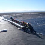
When laying large membrane sheets, several machines move forward in a staggered pattern like steps, leaving 20–30 meters between them. Power cables must be watched carefully to prevent the breakers from tripping.
At the start and end of each seam, the weld must overlap by 50 mm. At staggered T-joints, a handheld welder must be used to apply a patch. The circular patch must be larger than 150 mm, and the edges should be ground into a 45-degree bevel.
Auxiliary Tools & Surface Preparation
A variable-speed angle grinder is used to prepare the membrane surface by creating the necessary physical roughness. Operating speed should be kept between 3500 and 4500 rpm to prevent HDPE from overheating and becoming polished into a glossy surface. An 80-grit sanding disc is used to lightly break the smooth outer layer of polyethylene.
Grinding depth must be kept within 10% of the membrane thickness. For 1.5 mm liner, the groove depth must remain below 0.15 mm. Technicians use mechanical depth gauges for random spot checks to ensure the surface is not damaged beyond the safe limit.
The cleaning zone must extend 10–20 mm beyond the seam edge. Once the oxidized layer is removed, the newly exposed polyethylene allows the extruded molten material to bond tightly to the parent sheet. Areas that are not cleaned thoroughly are prone to false welds and peel failure later on.
The on-site grinding parameters are as follows:
- Abrasive disc: 80-grit semi-open coated disc
- Grinder speed: 3500–4500 rpm
- Bevel angle: 45 degrees
- Maximum grinding depth: 10% of the original membrane thickness
- Cleaning width: seam width plus 15 mm on each side
Once the physical surface has been prepared, chemical cleaning is carried out with isopropyl alcohol. HDPE often carries a trace amount of wax from manufacturing, and may also accumulate oil during transport and exposure. Industrial-grade isopropyl alcohol with 99.7% purity can dissolve these organic residues quickly.
Cotton cloth must not be used during wiping, because any residual fibers will char under welding heat and create micropores in the seam. Instead, use a 120 g/m² polyester filament lint-free cloth, which prevents foreign matter from being trapped inside the weld.
The chemical cleaning parameters are:
- Solvent purity: 99.7% isopropyl alcohol
- Wiping cloth: 100% polyester filament lint-free cloth
- Evaporation time: 10–15 seconds at 20°C
- Surface acceptance standard: no white marks and no water residue
Once the membrane surface is clean, a 1600 W industrial hot-air gun is used for positioning. Two HDPE sheets must be overlapped by 100–150 mm. The hot-air gun is used to make tack welds at intervals of 150–300 mm.
The air temperature at the nozzle must be kept between 350°C and 400°C. Each tack weld should form a spot 15–20 mm in diameter. The nozzle must remain 5–10 mm above the membrane surface to prevent local overheating and burn-through.
After the sheets are fixed in place, heavy-duty hook knives are used for major cutting work. A 60-degree hooked blade can cut through 2.0 mm polyethylene sheet without letting the tip puncture the 300 g/m² geotextile underneath.
Blades must be replaced every 50–80 meters of cutting. Layout marking is done with a 50-meter steel tape, and overlap lines are marked with silver or white wax crayon that contains no oily ingredients.
Ordinary oil-based markers contain solvents that can attack the polyethylene chain structure. Such ink must never be used in the weld zone. A proper silver wax crayon provides accurate guidance for the welding machine and keeps overlap error within 5 mm.
The positioning and cutting parameters are:
- Hook blade angle: 60-degree high-carbon steel
- Blade replacement frequency: every 50–80 meters of cutting
- Overlap width: 100–150 mm
- Marking tool: non-oily silver wax crayon
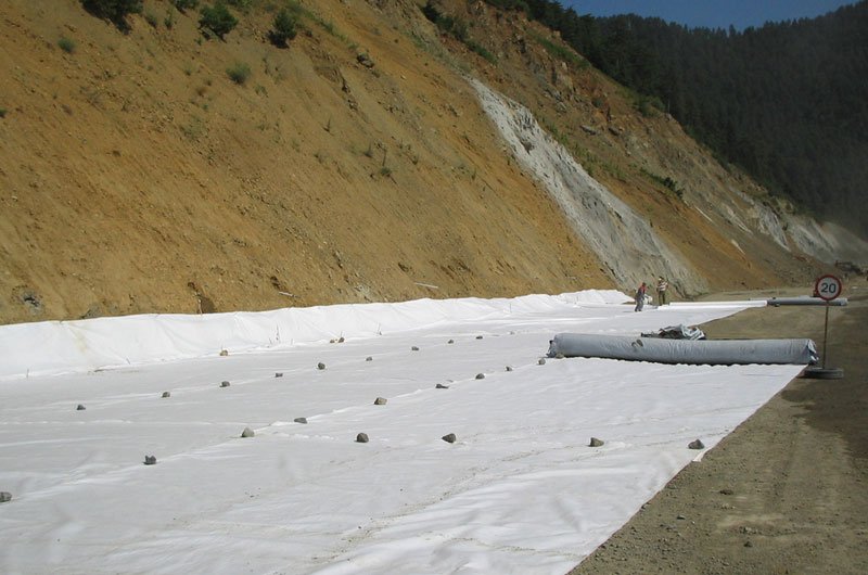
To stop the membrane from shifting in the wind, sandbags are used as ballast. Each woven sandbag should weigh 15–20 kg. Over the membrane surface, the ballast should provide at least 5 kg/m² of downward load.
When wind speed reaches 20–30 km/h, sandbag spacing must be reduced to 2 meters. Strong wind can create airflow beneath the membrane, and if ballast is insufficient, the entire sheet can lift like a sail and tear away from the tack welds.
A handheld manganese-steel scraper is used to remove excess flashing produced during extrusion welding. After each meter of seam is completed, a 1.2 mm-thick scraper should trim away any raised bead more than 0.5 mm above the parent material. This helps maintain even stress distribution and reduces cracking risk.
The preheating shoe at the front of the extrusion welder is made of PTFE. At working temperatures of 280°C, PTFE prevents molten polyethylene from sticking to the welding shoe, which helps keep forward resistance stable during welding.
The preheating shoe must be cleaned regularly with a brass brush. After 300–500 meters of continuous welding, carbonized polyethylene will accumulate in the grooves. A brass brush, which is softer than steel, can clean it away without damaging the PTFE coating.
Technical requirements for trimming tools:
- Scraper thickness: 1.2 mm, manganese steel
- Cleaning tool: brass brush softer than steel
- Roller material: silicone with Shore hardness 60–70
- End-pressure load: 15–20 kg
After a dual-track hot-melt seam is completed, the seam ends must be reinforced with a silicone roller of Shore hardness 60–70. Together with a 1600 W hot-air gun, this is used to finish the terminal sections that the machine cannot close fully. More than 15 kg of manual pressure must be applied to prevent moisture from entering through the seam ends.
Edge trimming should extend 30–50 mm from the seam end. The hot-air gun provides about 350°C of auxiliary heat, and the roller provides the pressure needed for physical consolidation.
Anchor trench finishing requires shovels and compactors. The trench should be 500 mm deep and 500 mm wide. After the membrane is laid into the trench, a small compactor operating at about 2000 vibrations per minute is used for layered backfilling.
The backfill must achieve at least 95% compaction, and each compacted layer must not exceed 150 mm in thickness.
Quality Control
Incoming Material Inspection
Every roll of geomembrane delivered to site must be accompanied by its corresponding MQA certificate. The resin batch number is the first item to verify. For HDPE membrane, density must remain between 0.941 and 0.958 g/cm³. When checked with portable weighing equipment, each roll should weigh between 1.4 and 1.8 tons. For 1.5 mm membrane, a standard roll is usually 150 meters long and 7 or 8 meters wide.
During unloading, only nylon slings wider than 15 cm may be used. Steel cables are prohibited because they can damage the edges. Rolls must not be stacked more than 5 high, to avoid deforming the core of the bottom rolls. The storage area must be level and free of sharp stones. When ambient temperature exceeds 35°C, shade netting should be used to prevent thermal expansion from altering the internal stress state of the rolls.
Appearance inspection must cover 100% of the membrane surface. Scratch depth is a measurable acceptance criterion: for 1.5 mm membrane, if a scratch is deeper than 0.15 mm, the roll must be rejected or downgraded. Check for bubbles or black contamination spots larger than 2 mm in diameter. The edge trim deviation must not exceed 3 cm, otherwise the later 100 mm overlap width cannot be controlled accurately.
- Carbon black content: 2.0%–3.0%
- Carbon black dispersion: must be Category 1 or 2 under microscopy
- Thickness uniformity: among 10 test points, the lowest single value must be at least 90% of nominal thickness
- Tensile performance: yield strength for 1.5 mm membrane must exceed 22 kN/m
- Elongation: at break, the sample must stretch to more than 7 times its original length
Thickness must be measured with a dedicated micrometer at a constant pressure of 20 kPa. A full-width transverse check must be made every 50 meters to ensure average thickness meets the design requirement. For textured membrane, asperity height must be measured according to ASTM D7466, and should remain stable between 0.4 and 0.5 mm. If asperity height drops below 0.25 mm, the anti-slip performance on slopes will fail.
Chemical resistance is evaluated through oxidative induction time (OIT). Under a 200°C high-temperature pure oxygen test, the sample must resist oxidation for 100 minutes. For high-risk acid or alkali applications, the high-pressure OIT test must exceed 400 minutes at 150°C. These numbers determine whether the liner system can perform for 30 or even 50 years underground.
- Puncture resistance: 1.5 mm membrane must withstand at least 500 N
- Melt index: less than 1.0 g per 10 minutes
- Brittleness temperature: no cracking at -70°C
- Tear resistance: at least 187 N in single-axis testing
After delivery, one sample set must be sent to a third-party lab for every 10,000 m² of material. The most time-consuming recheck is ESCR—environmental stress crack resistance. The sample is notched, stretched by 30%, and soaked in a 10% surfactant solution. If it fails within 500 hours, the batch may contain recycled plastic and must be removed from site completely.
The thermal expansion coefficient also affects layout and installation allowance. HDPE membrane has a linear thermal expansion rate of 0.00012. With a 20°C temperature swing, a 50-meter sheet can change in length by 12 cm. During inspection, the actual membrane surface temperature must be recorded, because it affects final layout adjustments.
All incoming records must be entered into an electronic log, with each roll linked to its production line number. Inspectors must spray the date of arrival and an acceptance mark on the first 30 cm of every roll.
Trial Welds
At 7:30 every morning, the dual-track hot wedge welder on site is switched on. Preheating must continue for 15–30 minutes. Depending on dew conditions and ambient temperature, the operator sets the wedge temperature between 380°C and 420°C. From the HDPE roll scheduled for that day’s work, a sample piece 1.0 meter long and 0.3 meter wide is cut using a utility knife.
The two sample sheets are overlapped with an exact seam width of 120 mm. Once the machine’s red light turns green, the operator feeds the sample into the silicone pressure rollers. Travel speed is controlled at 2.5–3.5 m/min. The fresh seam comes off the machine at over 100°C, so it must be set aside in the shade for 5–10 minutes before it can be handled.
Only after the surface has cooled completely can testing begin. Workers use a white marker to record the machine number, the operator’s name, and the travel speed used on the sample.
- A dumbbell-shaped steel die is used to punch out strips exactly 25 mm wide
- Each trial weld must provide 10 strips: 5 for shear, 5 for peel
- For the common 1.5 mm thickness, shear strength must reach at least 21 N/mm
- Peel strength must reach at least 14 N/mm; for extrusion-gun repairs, at least 11 N/mm
- Failure must occur in the parent sheet, with no visible crack in the welded zone
Inside the site shed, a portable electric tensile tester is set up. Each strip is clamped at both ends, with a gauge length of 50–100 mm between the grips. The tester then pulls at a constant rate of 50 mm/min. If even one out of the five test pieces fails to meet the standard, the operator must either increase the welding temperature by 10°C or reduce the travel speed by 0.2 m/min.
After adjusting the settings, a new sample must be cut and the whole procedure repeated. At 1:30 p.m., after lunch, the test must be repeated again, no matter how good the morning results were. By midday, the black membrane surface may rise to 60°C, becoming softened by solar heating. If the morning settings are used unchanged, the membrane can easily burn through or become brittle.
This afternoon trial is intended to correct for the parameter shift caused by solar heat. If the site anemometer shows wind speeds above 20 km/h, a windbreak tarp must be erected immediately. If air temperature falls below 5°C or rises above 40°C, work must stop. If there is any moisture on the membrane surface, every corner must be carefully dried with a hot-air gun.
Before using the handheld extrusion welder, an angle grinder must be used to remove the oxidized surface layer. For 1.5 mm membrane, grinding depth must not exceed one-tenth of the thickness, or about 0.15 mm.
- Ground surfaces remain valid for only 20 minutes; after that, oxidation returns and the area must be ground again
- Failed trial-weld samples must not be discarded; they must be archived in the site QA room until final project handover
- Once powered on, the extrusion welder must idle for 10 minutes to purge the charred plastic left inside the barrel from the previous day
- The ground area must extend 6–12 mm beyond the actual seam so the new molten plastic can bite in more firmly
- The welding rod used in the extrusion welder must match the composition of the installed liner exactly
If, during testing, the two sheets peel apart smoothly like adhesive tape, it means the plastic never truly fused. In most cases, this is because of fine dust contamination or because the hot-air temperature never reached 270°C. The inspector must record the ambient relative humidity as well; once it exceeds 80%, water vapor is easily trapped between the sheets and weakens the seam.
Every person on site carries a record sheet and writes down the daily operating condition of dozens of machines.
- Welder ID sprayed on the housing: W-02
- Time of strip cutting and tensile test: 08:15 a.m.
- Air temperature: 18°C; infrared membrane temperature: 16°C
- Wedge heating temperature: 400°C
- Travel speed reading: 2.8 m/min
- Test result: all 5 specimens failed in the parent sheet
- QA inspector signs and dates the record by hand
The site supervisor also spot-checks failed test strips from time to time to prevent falsified records. If the same machine fails tensile testing three consecutive times, it is shut down immediately. The mechanic must then dismantle it and check whether the silicone pressure rollers have worn flat or whether the heating element has partially burned out.
Quality Supervision
Once the morning startup tests are complete, two dual-track welders move into the base of the large reservoir area. The supervisor uses an infrared thermometer from 1 meter away to scan the hot wedge, and the display reads 395°C. The QC inspector walking beside the machine bends down and watches the two black molten edges coming out from under the silicone rollers. The machine advances at 2.8 m/min.
Ahead of it, another worker walks backward holding a dry pure-cotton towel. He wipes the 150 mm overlap strip of the lower sheet clean before the machine reaches it. The moment even a trace of dust blows onto the area—or even one droplet of dew the size of a soybean is brushed off nearby—the wiping force must be increased immediately. The two large HDPE sheets lie one over the other, guided by white chalk lines.
The overlap width shown on the drawings is 100–150 mm, and the edge of the track roller must run precisely along that line. The inspector measures it with a steel tape every 50 meters. If the overlap has shrunk to 80 mm, the operator must stop immediately. The seam leaves a 12 mm channel in the middle, reserved for later air-pressure testing.
- The width of the molten bead squeezed out by the machine must never exceed 3 mm
- The track imprint depth on the membrane surface must remain below 0.15 mm
- The offset between upper and lower sheet edges should stay around 50 mm to help shed rainwater
- After every full 150-meter roll, the pressure rollers must be cleaned of residual polymer
At locations where three sheets meet, the dual-track machine is no longer effective. Three layers of 1.5 mm sheet create a step 4.5 mm high. If the machine climbs over it, it leaves a triangular void. Workers call this a T-joint. The supervisor uses a wide utility knife to shave down the extra triangular edge from the middle sheet.
Once the step has been beveled, it is covered again with the handheld extrusion welder. The welder—carrying a 20 kg extrusion unit—sets the preheat air to 260°C. A 4 mm plastic rod feeds into the machine, which extrudes black molten plastic at a rate of 2 kg/hour, gradually sealing the step completely.
| Inspection Point | Tool Used | Standard Value | Corrective Action |
|---|---|---|---|
| Pressure roller force | Spring force gauge | 15–20 kg | Tighten the pressure-adjustment screw with a wrench |
| Extrusion nozzle temperature | Infrared thermometer | 260–280°C | Adjust the temperature dial on the rear handle |
| Edge indentation | Vernier caliper | Depth less than 0.15 mm | Reduce track speed by 0.2 m/min |
| T-joint transition slope | Steel tape | Slope transition greater than 50 mm | Grind for another 3 minutes |
At midday, under strong sun, the black membrane surface may rise to 65°C. The sheet begins to balloon upward into half-meter-high bulges, commonly called fish mouths. If the track welder runs across them, it will crush and rupture the membrane. Workers cut a 300 mm slit along the crest of each bulge.
The opened sheet then lies flat again, overlapping itself by about 75 mm. The welder grinds a rough strip about 100 mm wide along the overlap, keeping grinding depth at 0.15 mm—just enough to remove the smooth oxidized surface and expose a roughened texture for the extrusion weld to grip.
- Square patches over punctures must have all four corners trimmed into 25 mm radius curves
- Patch edges must extend at least 150 mm beyond the center of the defect
- Grinding time with the angle grinder must not exceed 20 minutes; after that, the abrasive disc must be replaced and the area reground
- A puncture may be repaired only twice; if a third repair is needed, the entire panel must be cut out and replaced
- The extrusion nozzle must be held at a 45-degree angle to avoid burning through the intact sheet below
By 5:30 p.m., once the strong sunlight fades, it becomes easier to locate tiny defects. The QC inspector walks slowly along the day’s seams with a 500-lumen flashlight held close to the ground at a 30-degree angle. At a pace of about 10 m/min, they inspect several kilometers of weld line. Under side lighting, even the slightest raised spot or unsealed pinhole casts a distinct shadow.
If a leak smaller than 3 mm is found, the inspector circles it with a white paint marker, writes the time—say 17:45—and notes the welder’s ID, such as W-07. The supervisor then returns to that spot, cuts a 150 mm circular patch, and the worker repeats the full grinding, preheating, and extrusion process to seal it completely.
At 9 p.m., the supervisor sits in the site office sorting through a thick stack of inspection drawings. Across the vast work area, 75 long seams were completed that day, each marked with the recorded ambient humidity of 65%. The hand-drawn layout is covered with dozens of red triangles, each corresponding to one of the day’s detected 3 mm pinholes. Those 300-plus real test numbers are all submitted to the supervising engineer’s office the next morning for archiving.
Common Pitfalls to Avoid
Inadequate Surface Flatness
A geomembrane only 1.5 mm thick may be laid over a jagged stone whose exposed tip is just 8 mm wide. If the reservoir water above reaches a depth of 10 meters, the pressure at the bottom rises to 100 kPa. At that point, the membrane is being forced down over that tiny point like a balloon pressed onto the tip of a needle.
On a site covering 5000 m², the human eye cannot detect these subtle irregularities. Place a 3-meter aluminum straightedge across the compacted subgrade, and you may see clear light beneath it. A feeler gauge slid into the gap might show a local void of 28 mm, far beyond the allowable flatness limit.
There is a rigid numerical standard for removing rocks and depressions from the subgrade:
- The gap beneath the straightedge must never exceed 20 mm
- Any stone projection with a detectable sharp edge must be removed completely
- All shrub roots must be excavated to a depth of at least 300 mm
- Any depression deeper than 40 mm must be backfilled with fine sand
- Any hard soil clod larger than 10 mm in diameter must be screened out
A 14-ton double-drum roller may compact the site repeatedly. If the moisture content of the soil is 5% below optimum, the top 100 mm can become as hard as iron, while the soil 200 mm below remains as loose as flour and unable to carry the load above.
As the reservoir is filled, the water level may rise by 1.2 meters per day. Pressure at the base keeps increasing, and the loose underlying soil may finally collapse under the weight of hundreds of thousands of tons of water. A 5 m² area may suddenly subside by 150 mm, leaving the membrane unsupported.
HDPE can generally elongate only about 12–15%. If the ground within a zone only 500 mm wide suddenly drops by 150 mm, the membrane is forced to stretch more than 18%. The polymer chains begin to break, and a 2.5-meter tear can quietly open beneath the water.
The subgrade fill must be selected almost as carefully as flour:
- The clay used to refill low spots must have particle size controlled below 2 mm
- The sand cushion layer above it must be at least 150 mm thick
- Compaction test readings must reach 95% of the heavy Proctor standard
- All hard soil lumps larger than 50 mm must be removed
- Lab-tested soil must contain less than 3% rotted leaves or vegetation
Tiny debris left on site can be surprisingly destructive. A discarded welding rod 30 mm long and 3.2 mm thick may remain hidden in the lower soil layer. When a 20-ton gravel truck passes nearby, vibration can gradually lift that metal fragment to the surface.
A 100 mm layer of river sand over the soil works like a cushion beneath the membrane. The sand must all pass through a 10-mesh sieve, with no particle larger than 2 mm. A small tractor dragging a 4-meter steel leveling screen can then smooth the area evenly.
Four workers stand shoulder to shoulder and clear a 6-meter wide working strip. Each uses a wide, flat-blade shovel to scrape off the top 10 mm of loose surface material. In less than an hour, a 5-liter bucket can be filled with rusty nails, broken glass, and discarded wire.
The proper tools for this rough groundwork are:
- A rigid 3-meter aluminum straightedge for flatness checks
- A smooth-drum roller weighing 14–18 tons
- A laser level with elevation error no greater than ±10 mm
- A metal standard sieve with 2 mm mesh
- A flat-blade steel shovel with a blade width of 300 mm
Now imagine the site has just had a 15-minute light rain. In low areas, shallow puddles about 5 mm deep remain. If the membrane is laid over this wet mud, moisture evaporating from the ground becomes trapped between the impermeable liner and the soil.
By noon, the surface temperature may rise to 36°C. That trapped water heats up, the vapor expands rapidly, and an 8-meter wide membrane can balloon upward into a blister 300 mm high, completely distorting the surface.
If a crawler dumper drives over that blister, the extra membrane gets crushed into a permanent fold. A 2-meter long crease then becomes a lasting stress point, and any future tension in the sheet will concentrate there until the membrane tears.
Before unrolling any membrane, the loose sand on the ground must be removed. Workers use an industrial blower with air speed up to 200 km/h to sweep away 0.1 mm dust particles. After cleaning, an adult walking over the prepared surface should leave footprints no deeper than 2 mm.
If the soil moisture exceeds 20%, the roller will create “rubber soil.” The ground will bounce like a sponge, and the surface may crack into a network of fissures up to 30 mm deep. In that case, excavators must remove the top 400 mm of weak soil, replace it with 150 mm of crushed stone, and then cover it with 250 mm of coarse sand.
Excavator bucket teeth can easily gouge long grooves while grading. These grooves are often 30–50 mm deep. Workers must use landscape rakes to pull the loose soil back level along the direction of drainage, reducing height differences to within 5 mm.
Even something as small as a discarded plastic bottle cap can be catastrophic. A hard cap 30 mm in diameter, half-buried in the soil, can remain hidden after covering and compaction. Its toothed edge may then cut 0.5 mm into the underside of the membrane, sharply reducing puncture resistance.
Anchor Trench Does Not Match the Design
On a slope as steep as 45 degrees, thousands of square meters of 1.5 mm geomembrane may be installed. Without the anchor trench at the top, the entire liner mass—possibly several tons—would slide downslope like a giant chute. To save fuel, excavator operators often reduce a 500 mm trench to only 300 mm.
Measure it with a tape, and the depth is often only about 250 mm. That amount of soil cover weighs less than 0.1 tons, far too little to hold a full 6-meter wide roll of membrane. Once the reservoir is filled, wave action on the water surface can pull the buried membrane edge straight out of the trench.
| Anchor Trench Parameter | Design Standard | Noncompliant Site Value | Result |
|---|---|---|---|
| Trench cross-section | 500 mm × 500 mm | 300 mm × 300 mm | Insufficient hold-down force; liner slips out |
| Distance from slope crest | 1000–1500 mm | 300–400 mm | Crest soil fails and collapses |
| Bottom corner radius | R = 300 mm | 0 mm (sharp corner) | Stress concentration causes tearing |
| Total liner embedment length | 1500 mm | 800 mm | Frictional resistance reduced by 50% |
The survey line at the slope crest is often laid out carelessly. Sometimes it sits only 400 mm from the break in slope. That narrow strip of soil has to resist several tons of pull from below. If a rainstorm soaks it for 3 hours, the softened soil may shift downslope by 600 mm, pulling the anchor trench and membrane with it.
The trench edges must be smoothed by hand with a shovel. A 1.5 mm HDPE sheet bent sharply across a hard 90-degree corner experiences intense localized stress. Workers must shave down the inner edge of the trench to form a smooth radius of about 300 mm. When the membrane lies over that curve, the load is spread across 3 times the area, instead of being cut by a hard soil edge.
Backfill quality also follows strict rules:
- Remove all stones larger than 20 mm
- Never bury cut turf or roots in the trench
- Mud with moisture content above 25% must be spread out and dried first
- The backfill must not contain hard soil clods larger than 50 mm in any direction
- Sandy soil must include a certain proportion of fines
A handheld rammer weighing about 80 kg must compact the trench fill in layers. Workers bounce it through the trench three times, keeping each layer at no more than 200 mm thick. A compaction tester inserted into the soil must show a reading above 95%. Only once the fill is as hard as stone is the anchor considered secure.
The membrane must never be stretched tight across the trench bottom like a guitar string. A slack fold of about 150 mm must be left at the bottom. At 3 a.m., if the temperature drops below 10°C, thermal contraction can shorten the membrane by 1–2%. Without that 150 mm buffer, the shrinking force can rip open the seam at the slope crest.
If several 20-ton trucks drive along the crest road, their vibration transmits through the foundation into the anchor trench. If the trench fill is not properly compacted, gaps can open in the soil. Once a crack just 5 mm wide appears, rainwater can travel along the membrane and turn the backfill into slurry.
Sometimes temporary site soil contains foreign metal. A discarded No. 12 rebar stub about 150 mm long may get buried at the trench corner. As the overburden is compacted, its sharp tip can gradually puncture the membrane. Underground, a hidden 12 mm hole has already completely compromised the liner in that area.
Excavator bucket teeth are usually about 150 mm wide. During final grading, one careless pass can scrape across the already installed membrane edge. A 300 mm tear may be opened along the sheet edge. Any such damaged section must be cut away—it cannot simply be buried in the trench to save material.
Five essential tools are required for anchor-trench work:
- A 5-meter national-standard steel tape
- An electric rammer weighing at least 80 kg
- A standard 20 mm ring sieve
- A core cutter sampler with density-reading precision of 0.01 g/cm³
- A laser level to define the setback line along the slope crest
In the afternoon, the ground surface may reach 45°C. Under that heat, HDPE softens and its tensile strength can drop by about 20%. At that time, it is strictly forbidden to dump several tons of backfill stone directly into the trench. Material must be placed gradually by wheelbarrow and spread carefully with a flat shovel, so the softened membrane is not crushed or cracked.
After backfilling, the surface should also be covered with 100 mm of river sand. This protects the trench from rain erosion. The sand’s silt content must be kept below 5%. If you squeeze a handful in your palm and it refuses to form a lump, its looseness is suitable for drainage and cushioning.
If drainage behind the trench is poorly designed, a small pond can form there. Hundreds of liters of rainwater can seep into the trench wall, and the resulting lateral pressure can push a 500 mm wide soil wall out of line. In some projects, the trench bottom is additionally cast with 100 mm of plain C20 concrete, using sheer mass to lock the membrane in place.
A worker standing by the trench can test the finished anchor by pulling on the exposed membrane edge. If it can be pulled more than 20 mm, the compaction is clearly inadequate. A proper anchor system should not move at all—even if pulled by a pickup truck.
No Pre-Layout Planning
Starting membrane installation without a layout drawing is like patching a wound with random strips. A crane places a roll weighing 1.2 tons onto the muddy ground. Once unrolled, it measures 50 meters long by 6 meters wide. Three workers, with no layout drawing in hand, simply cut the straps and start rolling it forward along the edge of the pit. When they hit a corner and find 2 extra meters, the foreman pulls out a utility knife and cuts it off.
This kind of unplanned installation is one of the worst habits on site. Material that should have remained neat and continuous gets cut into useless fragments. Across a site of tens of thousands of square meters, strips less than 1 meter wide end up scattered everywhere.
Cutting without a calculated layout means creating hundreds of extra meters of seam for no reason.
The more seams there are, the greater the chance of leakage. When two 6-meter wide geomembrane sheets are joined, a dual-track welder has to run the entire length. Every extra 10 meters of seam adds roughly 200 potential weak points where false welds or missed welds may exist.
When workers lay sheets casually, seams often meet in a large cross shape on flat ground. The square edges of four sheets converge at a single center point. That area has been heated and reworked four separate times, and the polymer structure there becomes brittle and stiff.
Cover it with 300 mm of crushed stone, then fill the reservoir to 8 meters deep. The resulting water pressure pushes downslope, and the center of that cross-shaped joint can suddenly experience stress above 20 MPa. Within seconds, it may fail like a brittle cracker.
Experienced installers never allow cross-shaped seam intersections. Instead, they insist that seams be offset.
- Transverse seams in adjacent sheets must be staggered by at least 500 mm
- All seam intersections must form T-joints, not crosses
- When the welding machine reaches a T-joint, it must stop and the area must be ground for 150 mm
- A handheld extrusion welder must then place a 3 mm thick plastic buildup over the prepared area
On slopes, installation direction is even more critical. On a slope with a gradient of 15%, the membrane must be laid vertically from top to bottom, following the direction of water flow. A full 50-meter long strip should run continuously from crest to toe with no cross-cut.
Laying strips horizontally across a slope just to save material is like burying a time bomb in the reservoir.
A horizontal seam running all the way across the slope becomes the one line carrying the entire downslope drag force from the soil mass above. Within a few months, that 150 mm seam can be torn open by the weight of the sliding soil itself.
No transverse seam should be placed within 1.5 meters of the toe transition from slope to flat ground. The stress field at the toe is the most complex. The membrane must pass continuously from slope into the flat bottom so that the downslope tension can dissipate gradually.
A proper layout drawing is like a tailor’s cutting pattern. The drafter inputs the site’s three-dimensional coordinates into a computer. The software then calculates the ideal position of every 6 m × 50 m sheet. For a reservoir covering 7140 m², the exact number of rolls required can be calculated precisely.
Computer layout produces surprisingly valuable data:
- Total seam length can be cut from 8000 meters to less than 6500 meters
- Waste from offcuts can be reduced from 8% to below 2%
- The irregular cut sizes for 12 pipe penetrations can be marked in advance
- The welding route can be planned day by day, increasing output by 300 meters per day
With the drawing in hand, every roll receives its own unique six-digit ID before leaving the factory. When workers check location A-12 on the layout, the forklift places roll A-12 at exactly that position. Placement error must not exceed 200 mm.
Without that preplanned drawing, every cut on site becomes guesswork. Take an 800 mm diameter pipe penetration through a wall: four or five workers gather around it and start measuring by eye. If the cut goes off by 50 mm, a sheet worth thousands is instantly downgraded to scrap.
Miscalculate one angle, and tens of square meters of material are fit only for covering spoil piles.
To repair a wrongly cut opening, workers are forced to cover it with a 1-meter square patch. That patch alone creates another 4 meters of unnecessary seam. What should have been a smooth liner surface now carries a thick scar.
When a tensile machine later grips both sides of that patch seam and pulls, the gauge may reach only 150 N/cm before failure—even though the design requirement was 200 N/cm. Random field patching without proper design simply does not stand up to laboratory testing.
Irregular polygonal corners are especially risky. Imagine a sharp slope corner with an angle of only 45 degrees. If a rectangular membrane sheet is forced into that corner, the material will bunch up into three dead folds, each about 100 mm high.
A day in advance, workers should measure the area with a tape and send the dimensions to the technical team. The drafter can then draw a triangular insert on flat ground—for example, with a 3-meter base and an 8-meter height—based on isosceles geometry. Using an electric hot knife, the insert can be cut accurately and laid into the corner with a perfect fit.
The layout drawing must also account for thermal expansion under strong sunlight. Suppose 30 sheets are installed in Zone C at 9 a.m., each with an intentional extra overlap allowance of 20 mm. By 2 p.m., when the temperature rises to 38°C, the material may expand by 40 mm. That reserved allowance absorbs the extra length and keeps the surface flat and wrinkle-free.


Leave a reply