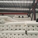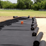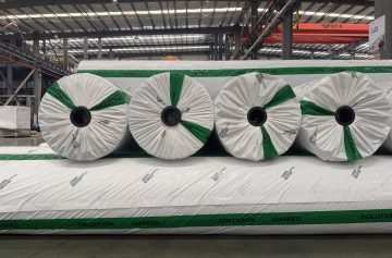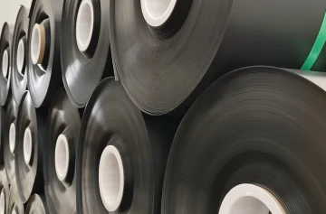

Reduce gravel settlement by correcting weak or wet support, drainage defects, unsuitable aggregate and inadequate compaction. A specified woven geotextile can keep aggregate and soil separated, but it cannot guarantee that a soft foundation will stop settling. A permeable woven geotextile is different from an impermeable geomembrane; waterproof liner details should not be copied into a gravel-road separation system.
This guide focuses on diagnosing settlement and planning a repair. For initial material selection beneath traffic-bearing gravel, see the woven-versus-nonwoven gravel-road guide.
Identify the mechanism before adding more gravel
| Observed symptom | Possible mechanism | Evidence to collect |
|---|---|---|
| Ruts with mud pumping into aggregate | Wet weak subgrade and loss of separation | Water source, soil condition, aggregate contamination and fabric continuity |
| Broad depression without obvious fabric damage | Settlement or consolidation below the road section | Survey history, fill depth, foundation profile and loading |
| Localized depression near a trench or utility | Poor backfill support, voids or leakage | Utility condition and investigation of the affected backfill |
| Loose surface with little underlying deformation | Aggregate grading, moisture or compaction problem | Aggregate test results, layer thickness and field density |
| Seasonal potholes or heave | Drainage and freeze–thaw effects | Seasonal water conditions, frost susceptibility and outlets |
These are diagnostic leads, not findings about a particular site. Restrict traffic where instability is evident and arrange investigation before further loading. Topping up a depression repeatedly may hide a continuing foundation problem.
Repair the subgrade and restore drainage
Remove unsuitable organic material and treat weak zones using the approved geotechnical repair. Excavation depth depends on the actual affected layer; it is not automatically 300 or 400 mm. Do not add lime, cement, root-control chemicals or bentonite without a designed, approved purpose and compatibility assessment.
Check runoff entry, crossfall, ditches, culverts and drainage outlets. A permeable fabric can pass water through its thickness, but it does not create an outlet or lower groundwater by itself. A lining that unintentionally traps water may worsen the roadbed condition.
Check grade calculations explicitly
A hypothetical 6 m-wide road crowned at its centre has a 3 m run to each edge. At 2% crossfall, the centre-to-edge drop is 3 × 0.02 = 0.06 m, or 60 mm. For a separate 10 m one-way crossfall, 1.5–2.5% corresponds to 150–250 mm. These examples demonstrate geometry; drainage grades must suit the road, terrain, erosion control and accessibility requirements.
Verify compaction rather than counting roller passes
The FHWA geotechnical pavement reference manual explains moisture–density relationships and the distinction between Standard and Modified Proctor compaction. The reference laboratory method matters: a percentage without its test basis is incomplete.
Relative compaction (%) = field dry density ÷ specified laboratory maximum dry density × 100. For an illustrative field dry density of 1.90 Mg/m³ and reference maximum of 2.00 Mg/m³, the result is 95%. That does not establish that 95% is the required acceptance criterion for every road or soil.
Moisture content, lift thickness, equipment and number of passes must be established for the material and conditions. A hand-squeezed soil ball or a surface that feels firm cannot verify a numerical moisture content or density. Use the project’s field testing, sampling and retest requirements. Do not cover frozen or pumping ground simply because it supports a person briefly.
Select aggregate for the specified road section
Review gradation, durability, particle shape, fines, drainage function and compactability together. There is no universal requirement that every road use one rock type, a 40–45° friction angle or a single fines percentage. Dense-graded road base and open-graded drainage aggregate have different functions.
Place aggregate in approved lifts and verify finished thickness and compaction. Vehicle weight alone cannot determine a safe layer thickness: axle loading, repetitions, tyres, subgrade strength, moisture and design life matter. Do not infer that a particular fabric weight automatically allows a ten-ton truck.
Specify the fabric by performance
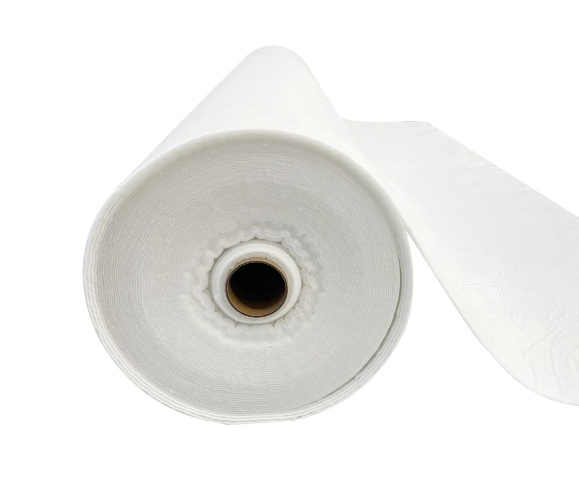
A woven fabric may provide separation and, where designed, reinforcement. The two roles require different evidence. ASTM D4632/D4632M provides grab breaking-load and elongation index results; a breaking load is not a vehicle capacity or a long-term reinforcement design value. Check the actual construction and both principal directions.
Specify soil retention and hydraulic performance using appropriate methods. ASTM D4751 addresses apparent opening size and ASTM D4491/D4491M addresses permittivity. A No. 40 sieve opening is not a universal filter criterion for clay, silt and sand; higher measured flow does not by itself prove excessive soil loss. Evaluate the soil–fabric combination and clogging risk.
Nominal GSM, colour and a roll’s appearance do not establish suitability. For a proposed nonwoven alternative, compare the required performance and obtain the specified approval rather than assuming either construction is universally superior.
Install continuous separation without damaging it
- Release the prepared support surface and confirm the correct grade and roll identity.
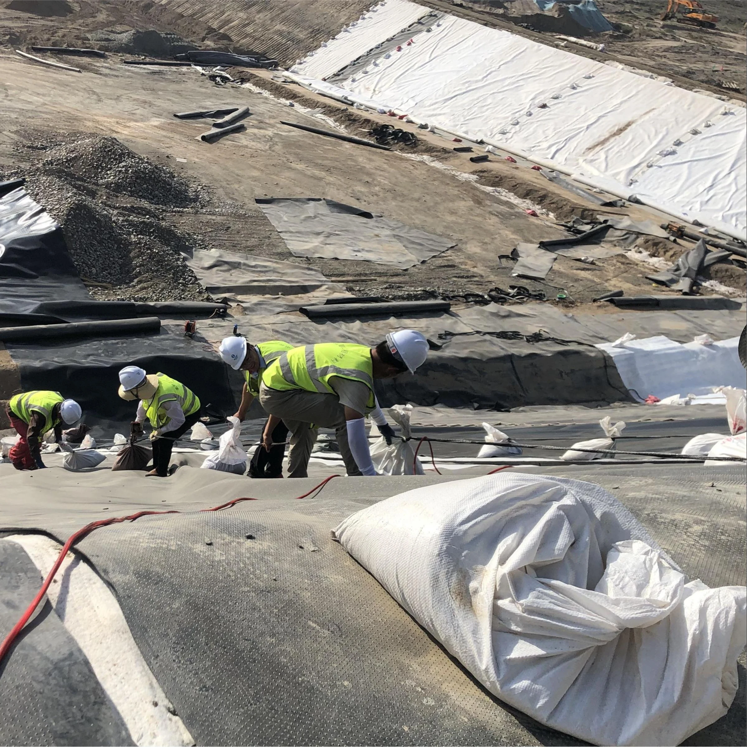
- Lay the fabric in contact with the surface without bridging, damaging tension or large folds.
- Use overlaps or sewn seams designed for the soil condition, installation forces and required continuity. Do not add waterproof sealant to a drainage fabric without a specified reason.
- Inspect joins, edges and repairs before aggregate placement. If seams carry structural demand, qualify and test them under the applicable specification.
- Place aggregate using the approved sequence and sufficient protective cover before equipment access. Avoid turning or braking directly on exposed fabric.
- Record coverage, damaged areas, repair acceptance, layer thickness and field test results.
Do not deliberately form large waves or stretch the fabric like a drum. Both can interfere with support and placement. Wind restraint and handling equipment should suit the roll and site; fixed pin spacing, sewing-machine speed or seam-strength percentages are not universal instructions.
Reconcile coverage and inspect the repair
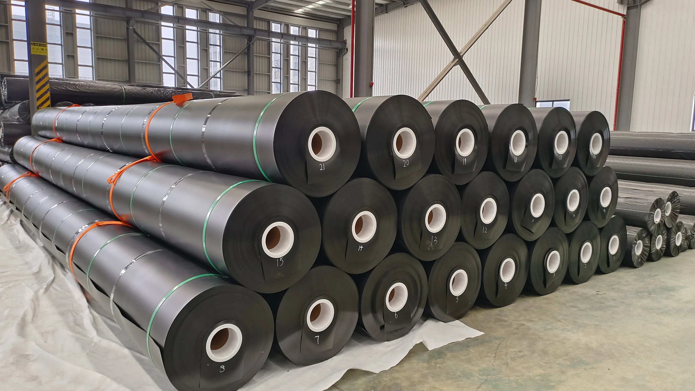
A 12.5 ft × 300 ft roll provides 3,750 ft², or approximately 416.7 yd² gross. Net coverage is lower after overlaps, trimming and details. Calculate purchasing quantities from the actual layout instead of treating the labelled area as finished road coverage.
After repair, record reference elevations, drainage condition and the accepted loading restrictions. Recheck after significant rainfall and early traffic. Renewed rutting, pumping or settlement warrants investigation of the underlying cause rather than an automatic switch to a heavier fabric.
Request material documentation with the road section, soil information, traffic, drainage arrangement and required test values. The responsible designer or project authority should approve a substitution or structural change.