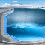
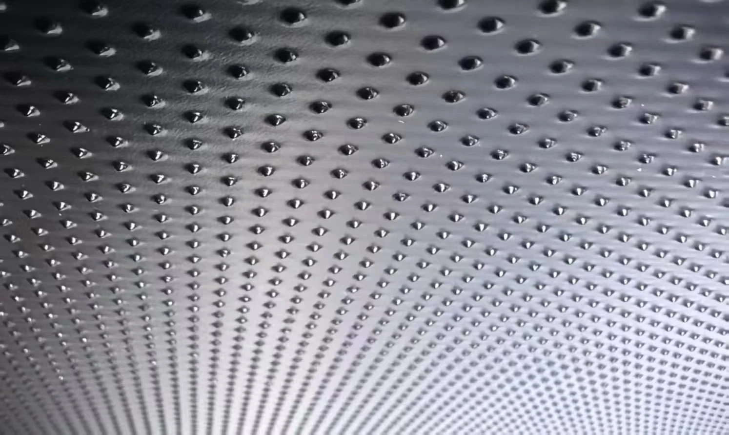
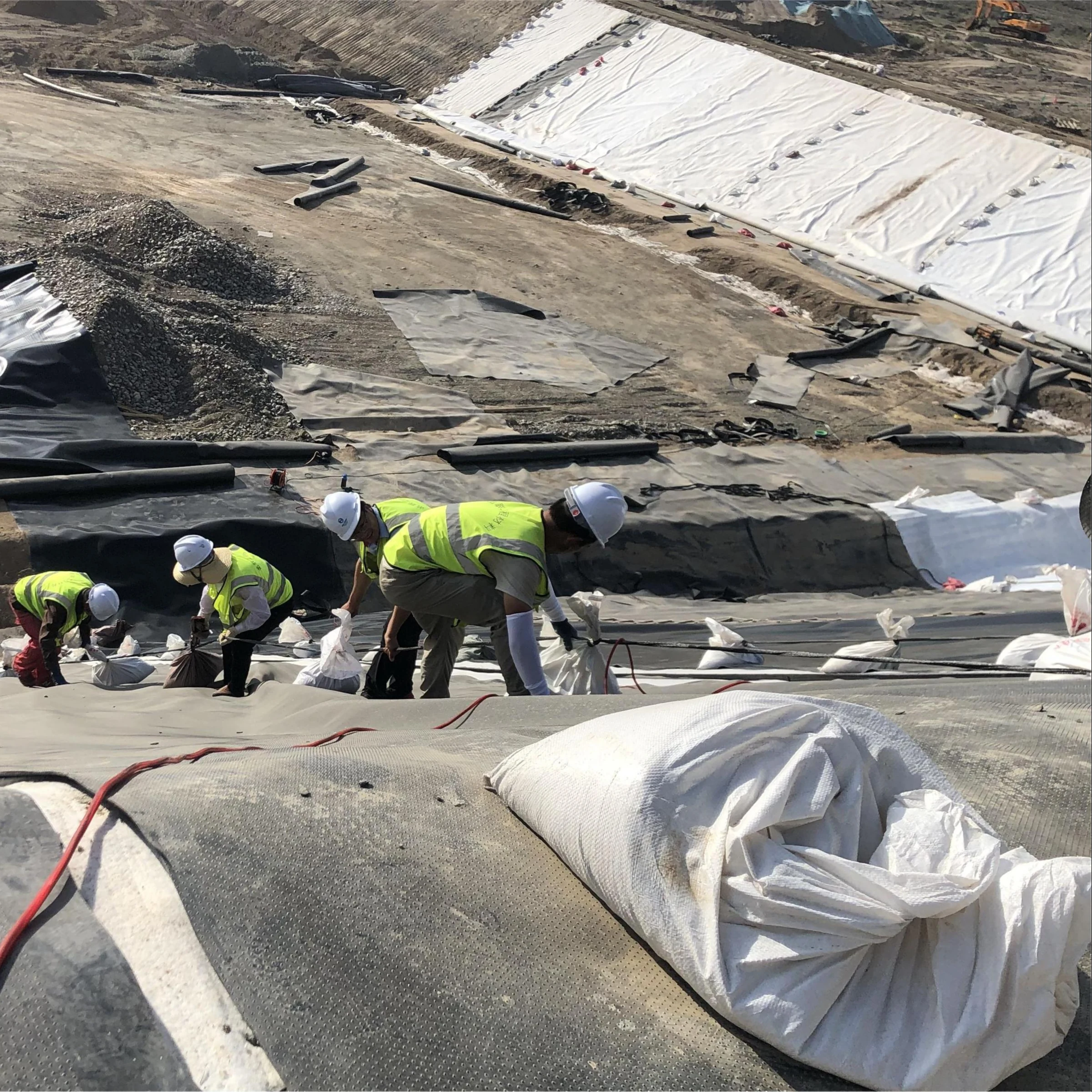
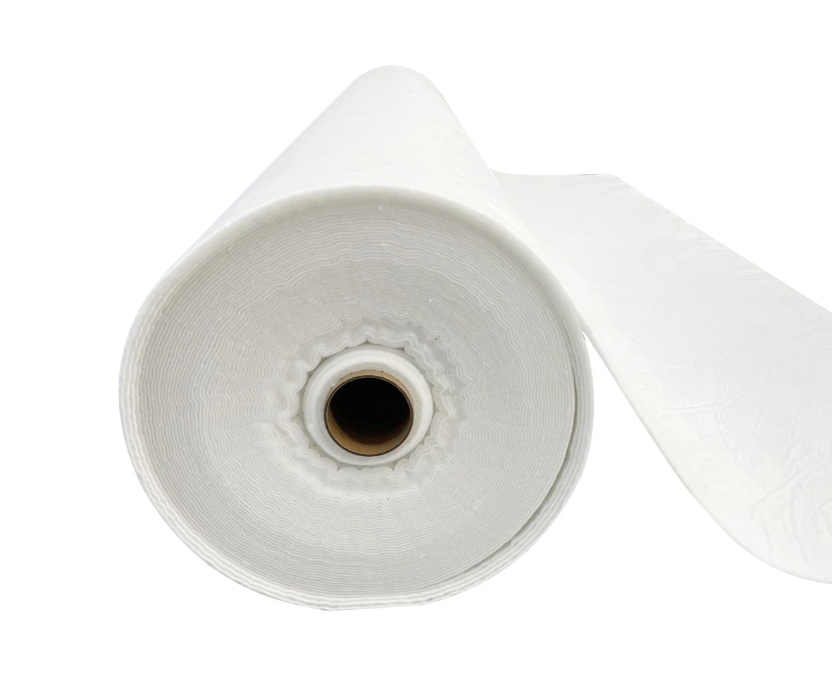

A landfill bottom liner is a coordinated barrier, drainage and monitoring system. Its layers must collect leachate, limit liquid head, resist chemical and mechanical loading, and allow construction quality to be checked. A geotextile, geomembrane, geosynthetic clay liner (GCL) and drainage composite perform different functions; adding layers without checking their interfaces is not a complete design.
For US projects, first identify the waste classification and governing permit. Municipal solid waste landfill (MSWLF) requirements and hazardous-waste landfill requirements are not interchangeable. State and site-specific requirements may be more demanding than the federal provisions discussed here.
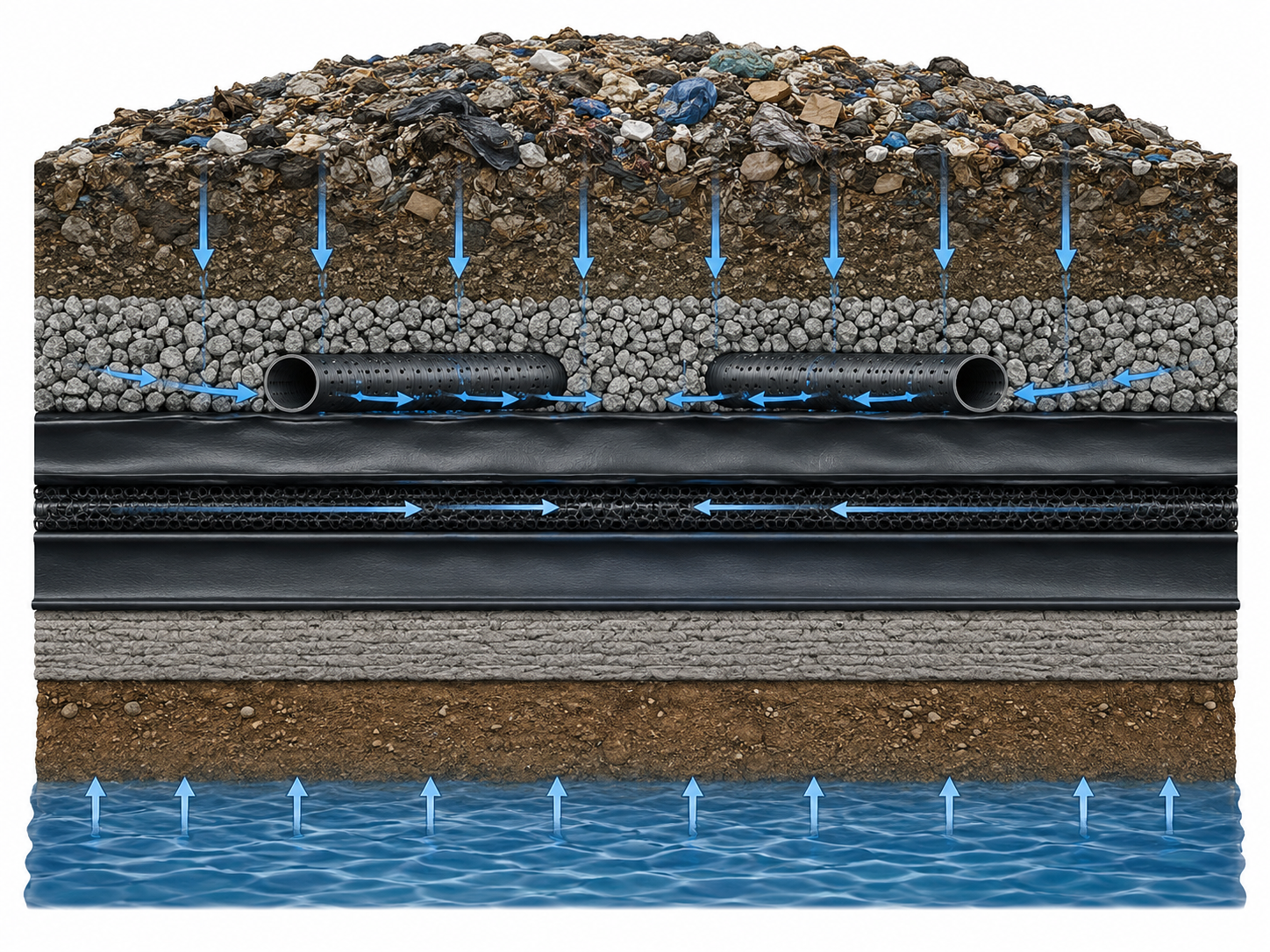
What each layer does
| Layer or component | Function | What to verify |
|---|---|---|
| Filter or separation layer, where specified | Limits migration of fines into drainage material | Soil retention, flow capacity, clogging risk and construction survivability |
| Leachate collection layer and pipes | Conveys liquid above the primary barrier to collection points | Long-term hydraulic capacity, settlement, loading, cleanout access and sump operation |
| Protection geotextile or engineered cushion | Reduces local damage to the geomembrane | Actual aggregate, placement method and design pressure; mass alone is insufficient |
| Primary geomembrane and low-permeability component | Provide the approved barrier arrangement | Material compatibility, thickness, contact, seam quality and defect control |
| Leak detection layer, where required | Collects and measures liquid passing the primary barrier | Position between barriers, drainage capacity, isolation and monitoring response |
| Secondary barrier and prepared foundation, where specified | Provide additional containment and support | Approved cross-section, stability, differential settlement and external groundwater pressure |
The precise order depends on the approved system. For example, the low-permeability soil or GCL intended to act compositely with a geomembrane should not be casually separated from it by an unapproved drainage layer. A drainage product belongs where the design needs controlled liquid transport.
US requirements: distinguish single-composite and double-liner systems
40 CFR 258.40 provides design routes for new MSWLF units and lateral expansions. Its prescribed composite route includes a flexible membrane at least 30 mil thick, increased to 60 mil for HDPE, over at least 2 ft of compacted soil with hydraulic conductivity no greater than 1 × 10⁻⁷ cm/s. Direct, uniform contact is required, and collection must maintain leachate depth below 30 cm. The section also provides a performance-based approval route; it does not impose one universal double-geomembrane section.
40 CFR 264.301(c) addresses applicable hazardous-waste landfill units with two or more liners and collection above and between them. Its specified bottom composite includes at least 3 ft of qualifying compacted soil. The interliner detection layer provisions include a slope of at least 1% and either qualifying granular drainage at least 12 in thick with conductivity at least 1 × 10⁻² cm/s, or qualifying synthetic drainage with transmissivity at least 3 × 10⁻⁵ m²/s. Scope, exceptions, alternatives and permit conditions must be checked.
These figures have different purposes. Do not transfer an interliner drainage criterion to every main pipe, or claim that all municipal landfills require a secondary barrier with a universal 30-year service life. A GCL substitution also needs the applicable design demonstration and approval.
Leachate collection: control head rather than quote a waste tonnage
Liquid pressure depends on density and head, not a standalone mass of waste. For a water-like liquid with density 1,000 kg/m³, a 0.30 m head corresponds to ρgh = 2.94 kPa. This is an illustration of hydrostatic pressure; it does not include waste loading, equipment loads or groundwater uplift, and a design should not aim to operate at its maximum permitted head.
Estimate inflows from site water balance, precipitation, waste characteristics and operating conditions. Check drainage lengths, grades after settlement, pipe openings, crushing resistance, sump capacity and pump reliability. An initially adequate pipe grade can be lost through differential settlement.
Use representative leachate chemistry for material and treatment decisions. COD, ammonia, salinity, temperature and pH vary with waste and landfill age. An unsupported universal concentration range or a statement that HDPE pipe lasts three to five times longer than PVC cannot substitute for a compatibility and loading assessment.
Drainage and filtration: keep the units straight
A hydraulic conductivity of 1 × 10⁻² cm/s converts to 1 × 10⁻⁴ m/s or 0.36 m/h. That conversion is not the actual drainage rate of a layer. For a simple saturated Darcy-flow example, q = ki; at gradient 0.01, the Darcy flux would be 1 × 10⁻⁶ m/s, or 3.6 mm/h. The assumed gradient and flow area are needed to calculate discharge.
For a drainage geocomposite, evaluate in-plane flow under the expected pressure, gradient, boundary materials and duration. ASTM D4716/D4716M addresses in-plane flow and transmissivity testing. Long-term intrusion, creep and clogging considerations belong in the design; an unloaded brochure value is not automatically the installed capacity.
For a geotextile filter, combine opening size, water-flow testing and soil compatibility. ASTM D4491/D4491M permittivity is expressed in s⁻¹, not cm/s. Thickness is needed to relate permittivity to cross-plane hydraulic conductivity under corresponding test conditions. A 300 g/m² fabric is not automatically a better filter than a 200 g/m² fabric.
Specify aggregate gradation, cleanliness, durability and placement without puncturing the barrier. Do not assume that a universal 92% Proctor density criterion describes the performance of every open-graded drainage layer. The construction specification must suit the selected aggregate and its function.
GCL integration: low permeability requires suitable conditions
A GCL contains bentonite in a manufactured geosynthetic assembly. Hydration and confinement help form a low-permeability barrier, but chemistry, moisture history, bentonite distribution and installation condition affect performance. The EPA GCL fact sheet, revised December 2001, is useful historical background on the technology and its application as an alternative liner component. It is not a current product approval or a universal conductivity guarantee.
Compare laboratory reports for the actual liquid and stress conditions. ASTM D6766-25 evaluates GCL hydraulic properties with potentially incompatible aqueous solutions. A water-based index result alone does not establish performance with a saline or chemically aggressive leachate. Do not assume that changes are always limited to 8–15% or that every product achieves 1 × 10⁻¹¹ cm/s.
Thickness and conductivity must be considered together. As an illustrative comparison, a 5–10 mm layer is about 1/120 to 1/60 of a 600 mm layer’s thickness, not one ten-thousandth. Those assumed thicknesses do not prove hydraulic equivalence: head, hydraulic gradient, defects, overlap behaviour and composite contact also matter.
For slope stability, evaluate both internal GCL shear and every adjacent interface. ASTM D6243/D6243M-26 is the relevant GCL direct-shear method. Results depend on hydration, normal stress, displacement and the actual adjacent material. A universal 20–35 kPa interface strength or a guaranteed 40% increase from textured HDPE is not a design value.
GCL handling and overlaps
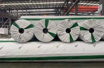
ASTM D5888-19(2024) covers storage and handling; ASTM D6102-23 covers installation. Check the manufacturer’s current instructions together with the approved drawings for side and end overlaps, supplemental bentonite, penetrations, slopes and cover placement.
Keep the receiving surface prepared, protect rolls and deployed sheets from unsuitable exposure, and inspect overlaps before concealment. Do not brush away a factory-applied bentonite edge treatment simply to follow a generic cleaning instruction. Do not puncture the GCL or underlying geomembrane with improvised stakes unless an engineered detail expressly requires and resolves the penetration.
End overlaps and longitudinal overlaps may have different requirements. Deployment direction, settlement allowance and anchorage should follow the accepted installation plan. Neither 300 mm overlap nor 0.3 kg/m supplemental bentonite is a universal requirement for all GCL products.
Verification: separate seam tests, ELL and operational monitoring
Destructive seam testing assesses weld strength. Air-channel and vacuum methods assess suitable seam configurations. Electrical leak location examines electrically detectable breaches under demonstrated site conditions. An interliner collection system monitors liquids during operation; groundwater wells investigate the surrounding hydrogeologic system. These are complementary measures, not interchangeable tests.
ASTM D5820 is an air-channel method for dual seams; it is not bubble testing through backfill. For the distinction between exposed and covered electrical surveys, see the ELL method selection guide. A leak detection sump must not be confused with a groundwater monitoring well.
Base action levels, sampling locations and response procedures on the permit and approved monitoring plan. Do not invent a universal 30 m well spacing, 15 cm daily water-level trigger or 0.05 L/m²/day allowable leakage by citing EPA analytical methods.
Maintenance and procurement checklist
- Obtain the approved cross-section, regulatory design route and design loading assumptions.
- Require traceable material identification, thickness and test reports, plus relevant compatibility and interface-shear evidence.
- Review collection capacity, cleanout access, pump redundancy, freezing exposure and arrangements for measuring interliner flows.
- Keep panel layouts, seam records, field test results, repairs and cover-placement records together.
- Use measured trends in head, flow and pipe condition to schedule maintenance within the permit requirements.
Jet-cleaning pressure, cleaning frequency and heat tracing must suit the pipe system and operating conditions. Fixed recipes such as 150–200 bar or 60–80 W/m should not be applied without the equipment supplier’s and designer’s review. Retain the evidence behind maintenance decisions instead of relying on unsupported savings or guaranteed payback claims.
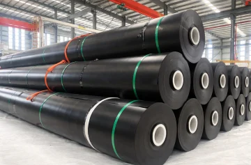
For material procurement, use our landfill geomembrane selection guide alongside the approved system specification. The purpose of the layer schedule is to establish a testable, maintainable design, not simply to maximise the number of materials supplied.