
A geosynthetic clay liner (GCL) and a compacted clay liner (CCL) can both provide low-permeability barriers, but they are not interchangeable on hydraulic conductivity alone. Compare thickness, hydraulic head, chemistry, construction conditions, stability and the required approval pathway. A lower laboratory k value does not automatically mean lower field leakage or lower installed cost.
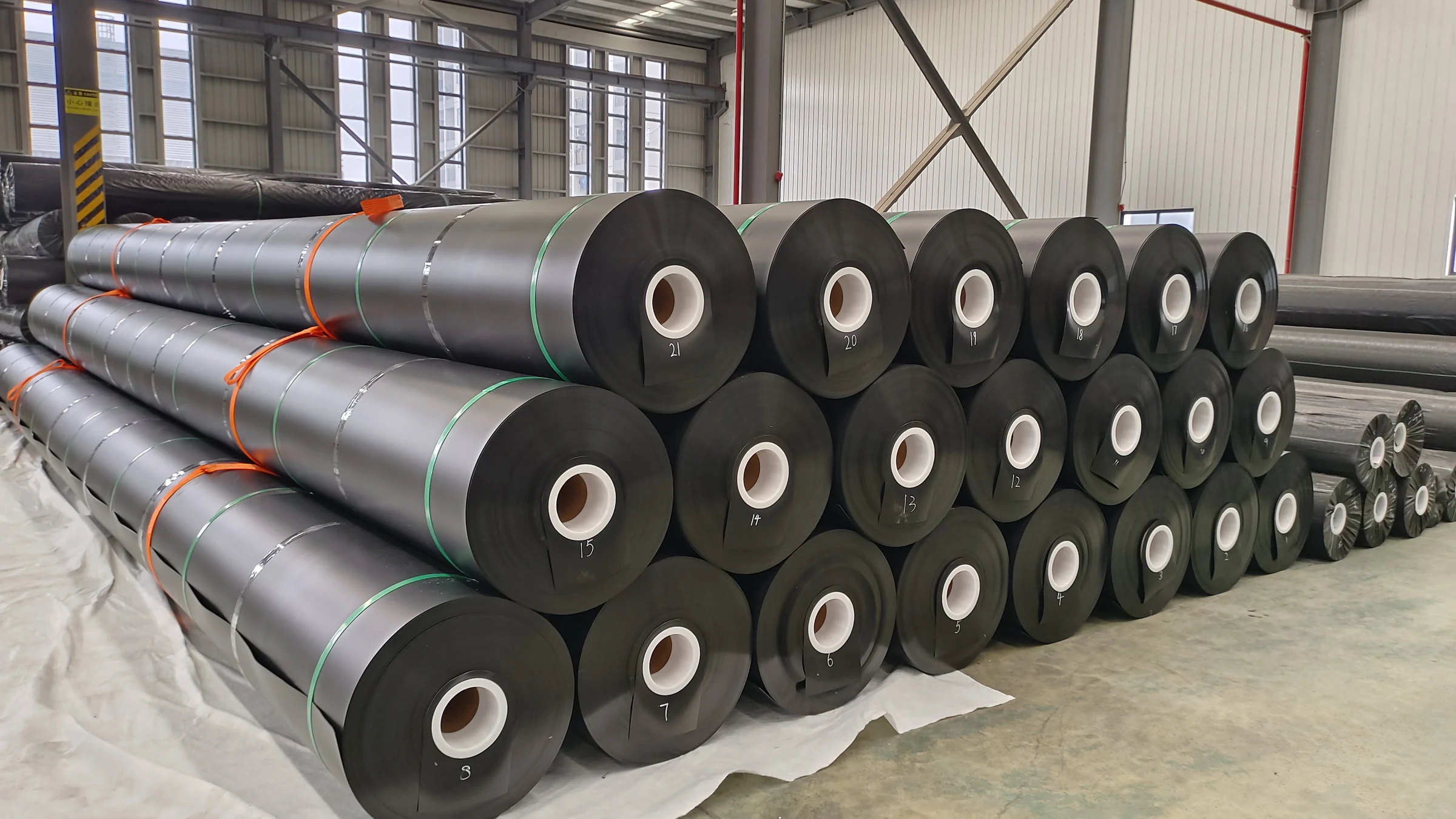
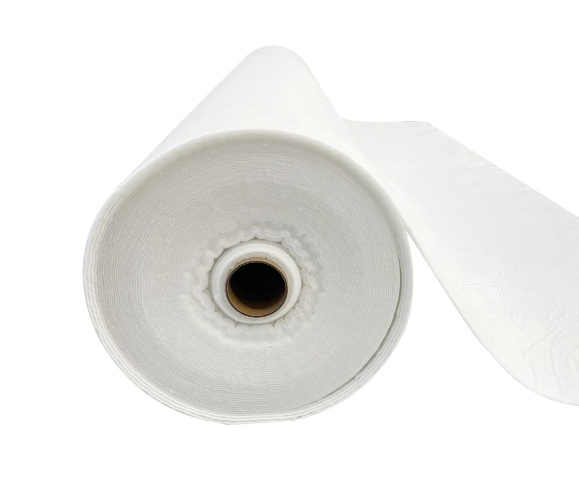
A GCL is a manufactured bentonite barrier, commonly held between geotextiles or associated with a polymeric backing. A CCL is a constructed soil layer placed and compacted to a specified condition. The comparisons below distinguish verified requirements from illustrative calculations; they are not claims about undocumented Jinseed project outcomes.
GCL versus CCL at a glance
| Decision factor | GCL | CCL |
|---|---|---|
| Barrier form | Relatively thin, manufactured bentonite roll system | Field-compacted soil placed in lifts |
| Hydraulic evidence | Flux/conductivity under stated hydration, confinement and permeant conditions | Conductivity demonstrated for the selected soil and construction condition |
| Construction controls | Roll handling, overlaps, damage, cover and hydration sequence | Borrow quality, moisture conditioning, lift bonding, thickness and compaction |
| Important vulnerabilities | Incompatible liquid, inadequate confinement, overlap separation or installation damage | Clods, poorly bonded lifts, moisture variation, cracking or differential settlement |
| Cost drivers | Product specification, delivered rolls, layout, handling, cover and CQA | Qualified soil availability, haulage, earthworks, conditioning and CQA |
| Selection advantage to investigate | Reduced bulk soil handling where the design and approvals allow it | Potential economy where suitable clay is nearby and the construction window permits it |
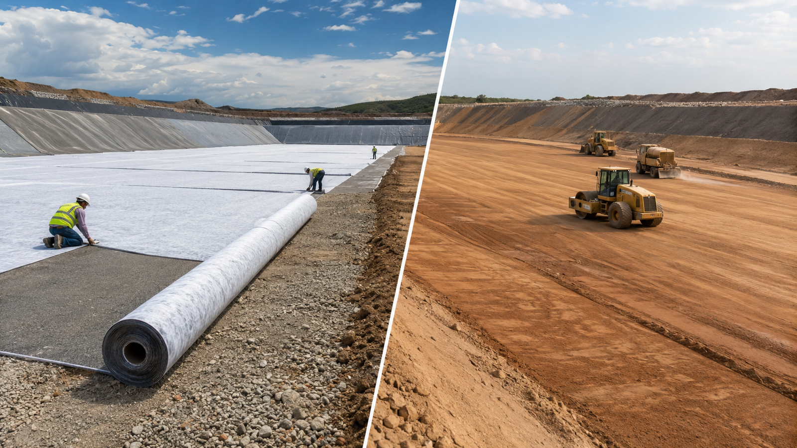
Check the regulatory pathway before substituting materials
For new municipal solid waste landfill units and lateral expansions using the prescriptive composite-liner route in 40 CFR 258.40(a)(2) and (b), the lower component is at least two feet of compacted soil with hydraulic conductivity no greater than 1 × 10⁻⁷ cm/s. The upper flexible membrane is at least 30 mil, or at least 60 mil when HDPE is used, in direct and uniform contact with that soil. The collection system must maintain less than 30 cm of leachate over the liner.
Replacing the specified soil layer with GCL is therefore not automatic compliance with paragraph (b). An alternative must follow the applicable performance-based approval process and site permit requirements. This MSW landfill provision is not a universal specification for reservoirs, tailings facilities or every containment application.
The exact conversions are 2 ft = 0.6096 m, 60 mil = 1.524 mm and 1 × 10⁻⁷ cm/s = 1 × 10⁻⁹ m/s. Specify construction tolerances so the accepted thickness meets the governing requirement.
The EPA’s GCL fact sheet, revised December 2001, describes GCL technology and historical applications, including alternatives to conventional barriers. It is useful background, but not a current product certificate or blanket approval for an individual substitution.
Hydraulic conductivity: include thickness and hydraulic head
Distinguish material conductivity from system leakage
Hydraulic conductivity k has units of length/time. Flux is flow per unit area. For one-dimensional saturated Darcy flow through a homogeneous horizontal porous layer of thickness t, with ponded water depth h above it and zero pressure head at its underside, the downward flux is q = k(h + t)/t. These boundary conditions matter.
The following arithmetic uses assumed material values solely to show the effect of thickness. It does not predict leakage through a geomembrane composite, where defects, interface contact and other mechanisms matter.
| Assumed input or result | CCL example | GCL example |
|---|---|---|
| Layer thickness, t | 0.60 m | 0.006 m |
| Hydraulic conductivity, k | 1 × 10⁻⁹ m/s | 5 × 10⁻¹¹ m/s |
| Ponded head, h | 0.30 m | 0.30 m |
| Hydraulic gradient, (h+t)/t | 1.5 | 51 |
| Calculated flux, q | 1.50 × 10⁻⁹ m/s | 2.55 × 10⁻⁹ m/s |
| Equivalent daily flow per area | 0.1296 L/m²/day | 0.2203 L/m²/day |
In this example, the GCL’s conductivity is 20 times lower, but its calculated flux is 1.7 times higher because the thinner layer has a larger hydraulic gradient. Different conductivity, head and confinement can change the comparison. The 0.60 m example is a calculation input, not the exact two-foot regulatory minimum.
Request comparable laboratory conditions
ASTM D5084 covers hydraulic conductivity testing of saturated porous materials with a flexible-wall permeameter. A CCL specification should link soil qualification and field construction controls to the required hydraulic performance. Density alone does not prove low conductivity; moisture, clod structure and bonding between lifts also matter.
ASTM D5887/D5887M measures index flux through saturated GCL specimens. Do not present its result simply as a field leakage guarantee. Record specimen conditioning, test liquid, hydraulic gradient, effective stress and the criterion used to complete the test.
For saline, high-calcium or other potentially incompatible liquids, use relevant compatibility evidence. ASTM D6766 evaluates GCL hydraulic properties with potentially incompatible aqueous solutions. Bentonite chemistry and hydration history can affect performance; a clean-water certificate does not establish suitability for every leachate or process liquid.
Hydration, source clay and stability
A CCL needs a qualified soil source and a demonstrated moisture–density working range that also achieves the specified conductivity. Avoid treating a plasticity index of 12 or 15, or a universal optimum-moisture tolerance of ±2%, as sufficient acceptance criteria for all clays. Qualify the proposed material and equipment through an approved test program and, where required, a trial pad.
A GCL needs a product-specific hydration and confinement plan. Do not apply a generic 24-hour spray-watering schedule or promise “80% hydration” without a defined measurement. Premature hydration can complicate handling; hydration by an unsuitable liquid can change performance. ASTM D6102 gives installation guidance and explicitly recognizes that different products and field conditions require different procedures. The project specification and approved manufacturer instructions control the sequence.
Adding a nonwoven protection layer does not convert unsuitable source soil into qualified compacted clay or make the foundation preparation unnecessary. Protection, hydraulic barrier performance and foundation support are separate functions.
For slopes, assess both internal and interface shear resistance using the actual materials and conditioning. ASTM D6243/D6243M addresses those GCL shear properties. A manufacturing peel-strength value in N/m is not an interface friction angle and is not a substitute for the stress-dependent shear parameters used in stability analysis. There is no universal hydrated friction angle or guaranteed factor-of-safety improvement for every GCL arrangement.
Construction and installation comparison
Prepare the foundation for either system
Both alternatives require a prepared foundation that meets the design’s support, deformation and surface requirements. Resolve soft spots, damaging protrusions and drainage issues before lining. A thin GCL can reduce the need to construct a thick clay barrier where substitution is approved, but it does not remove earthworks needed for grading or foundation remediation.
For CCL, establish the compacted lift thickness, equipment, passes, moisture conditioning and bonding of successive lifts through the approved construction method. Four compacted lifts of exactly 150 mm total only 600 mm; they do not add up to 609.6 mm. Surveyed final thickness and tolerances, rather than an approximate lift count, should demonstrate compliance.
Distinguish GCL overlaps from geomembrane welds
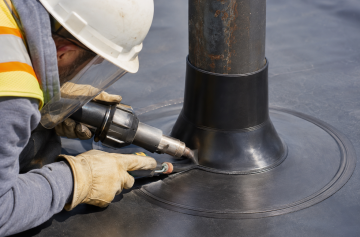
GCL overlaps require product- and project-specific widths, orientation, cleanliness and, where specified, supplemental bentonite. Geomembrane seams are a separate system with different preparation and testing. Do not apply a membrane welding allowance or a universal 0.5 kg/m² bentonite dosage to every GCL joint.
The CETCO BENTOMAT CL product page provides access to that product’s installation guide; use manufacturer guidance only for the relevant product and approved application. It is not evidence that all GCLs use identical details. Slope panel layout and cross-slope end joints require review for the actual stability and construction conditions; a blanket rule to run overlaps along contours above a 3% slope is inappropriate.
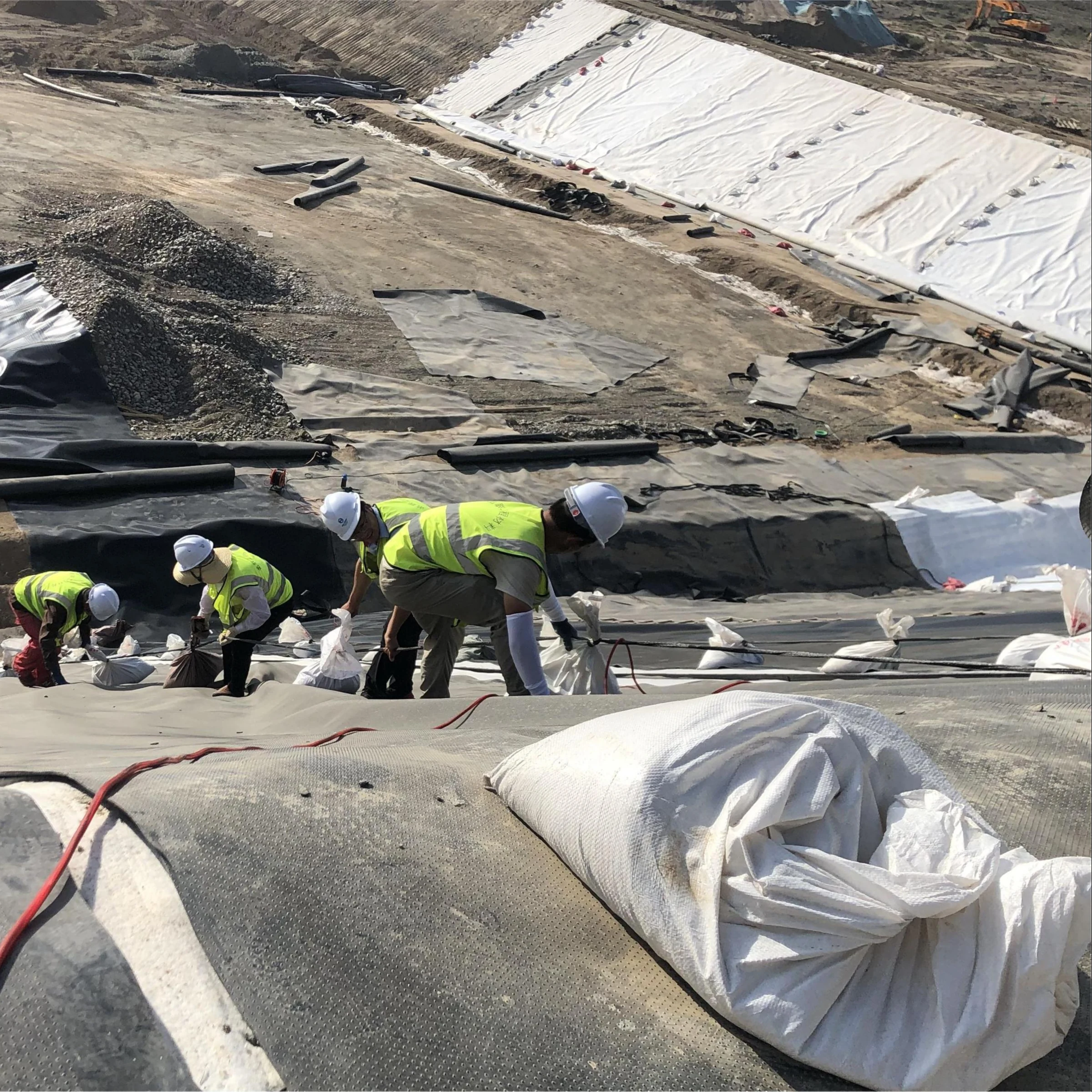
Document roll identification, panel layout, overlaps, terminations, repairs, cover placement and inspection hold points. Assess damage before covering rather than assuming bentonite swelling will heal any hole. The covering operation must preserve both the GCL and adjacent geomembrane.
Cost comparison: use a complete installed scope
Compare alternatives that meet the same approved performance objectives. For a 10,000 m² area, a 0.6096 m CCL represents 6,096 m³ of compacted soil before allowances. Convert this to borrow and transport quantities using measured density and volume-change assumptions. For a GCL take-off, calculate rolls from the panel layout, overlaps, terminations and usable offcuts rather than assuming delivered roll area equals covered area.
| Cost category | CCL quotation should include | GCL quotation should include |
|---|---|---|
| Materials and transport | Qualified borrow, excavation, haulage and conditioning inputs | Specified roll system, freight, accessories and layout allowance |
| Installation | Placement, moisture control, compaction and lift preparation | Unloading, approved lifting equipment, deployment, overlaps and cover |
| Quality assurance | Soil qualification, trial work, field checks and hydraulic testing | Conformance checks, panel inspection, repairs and compatibility evidence |
| Other design costs | Foundation preparation, drainage and geomembrane where required | The same scope, plus any alternative-design approval effort |
Hypothetical budgeting example: if qualifying and placing compacted clay costs USD 35/m³, 6,096 m³ costs USD 213,360 before other items. If a separately assumed GCL supply-and-install package costs USD 12/m² over a priced quantity of 10,500 m², it costs USD 126,000. The apparent USD 87,360 difference is not a market-price claim or a final saving: align cover, testing, foundation, approval, geomembrane and drainage costs before deciding. The 5% quantity allowance is illustrative and must be replaced by the actual layout.
Do not infer a fixed crew size, labor-hour ratio or schedule saving from roll coverage per truckload. Access, lifting equipment, weather, overlaps, cover placement and inspection can all govern productivity. A GCL can reduce clay-hauling and lift-compaction work without eliminating the construction or QA team.
Maintenance and the final selection
Neither barrier is maintenance-free. Assess the installed system’s susceptibility to settlement, wetting and drying, freeze–thaw exposure where applicable, chemical change and damage. An exposed installation defect may be straightforward to repair; access to a buried liner beneath waste or tailings can dominate the repair cost for either system.
Claims that every GCL has 40–55% of the annual maintenance cost of CCL, or that a failure of a different geomembrane proves the superiority of one clay barrier, need comparable project records. Without them, use a site-specific lifecycle estimate with stated inspection, intervention and access assumptions.
Before selecting GCL or CCL, confirm the approval pathway, liquid chemistry, hydraulic head, laboratory conditions, slope stability, source materials and complete installed quotation. For landfill applications, also review the complete bottom-liner system; the clay component cannot be assessed independently of the geomembrane, collection layer and construction quality.