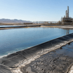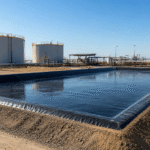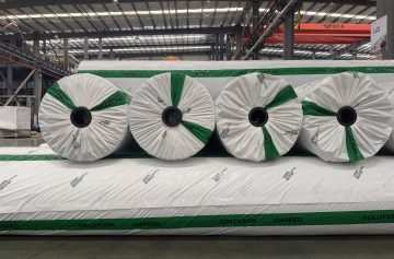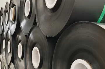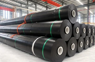
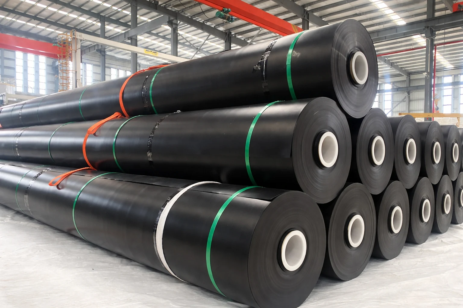
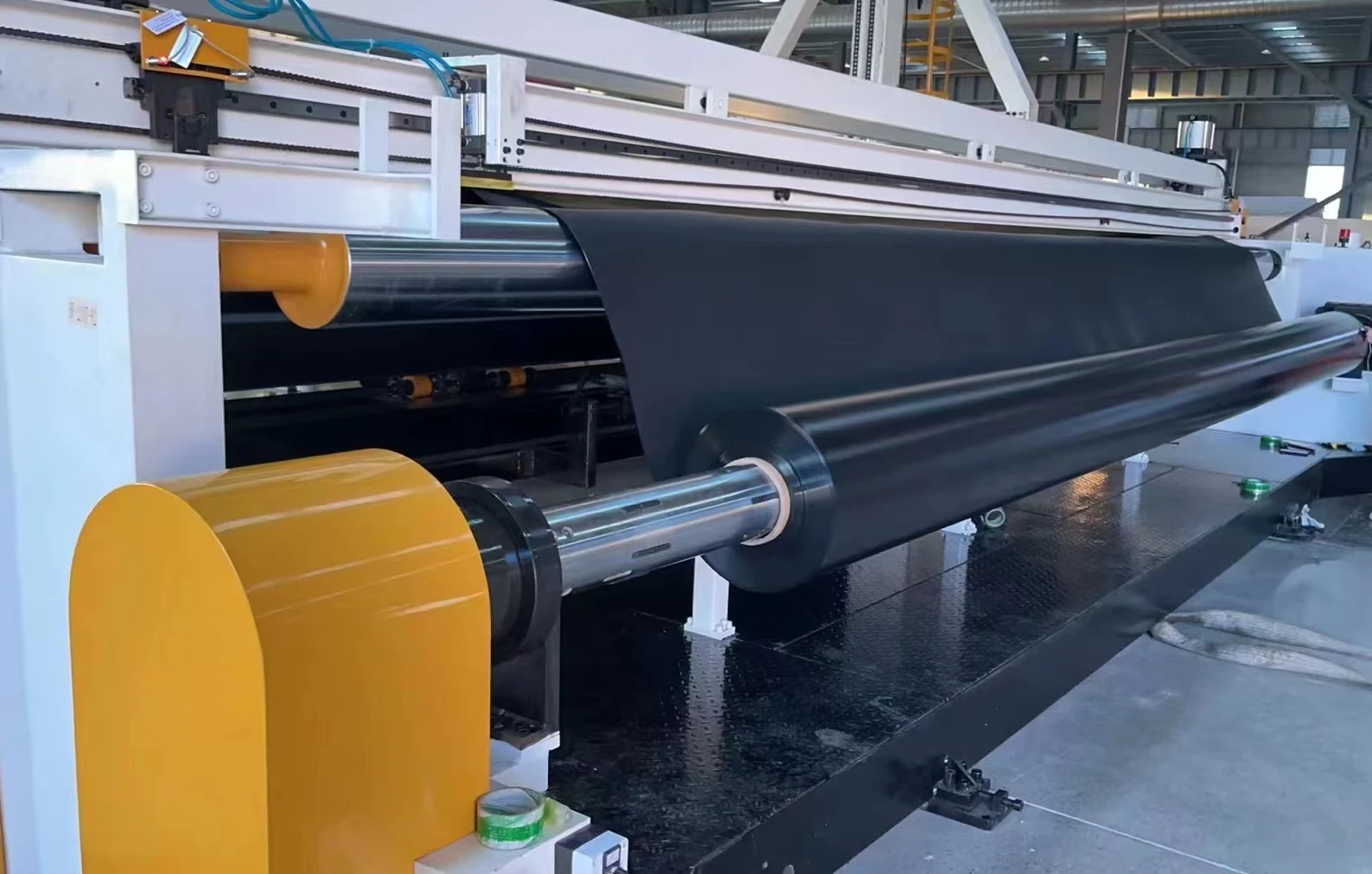
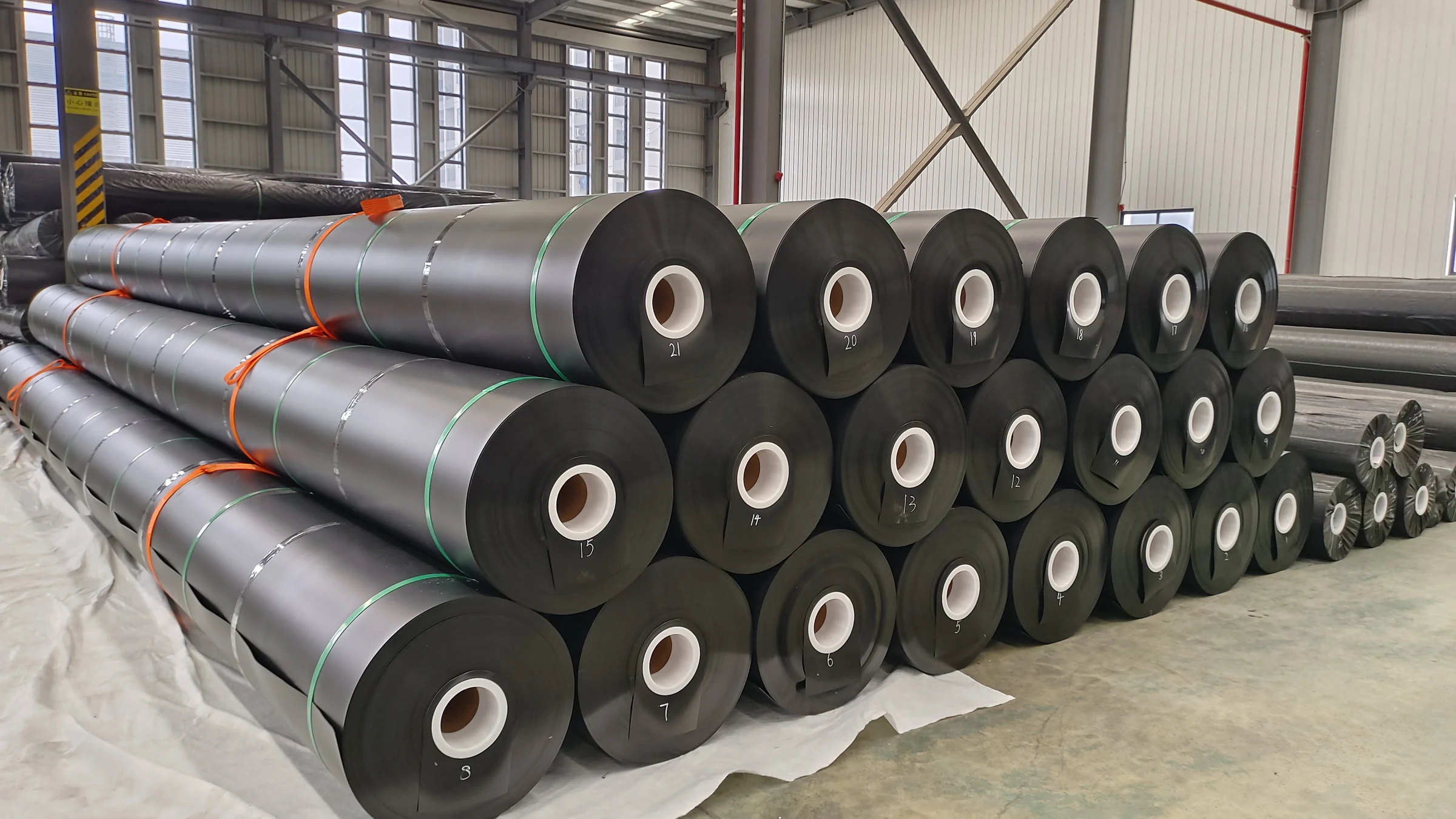
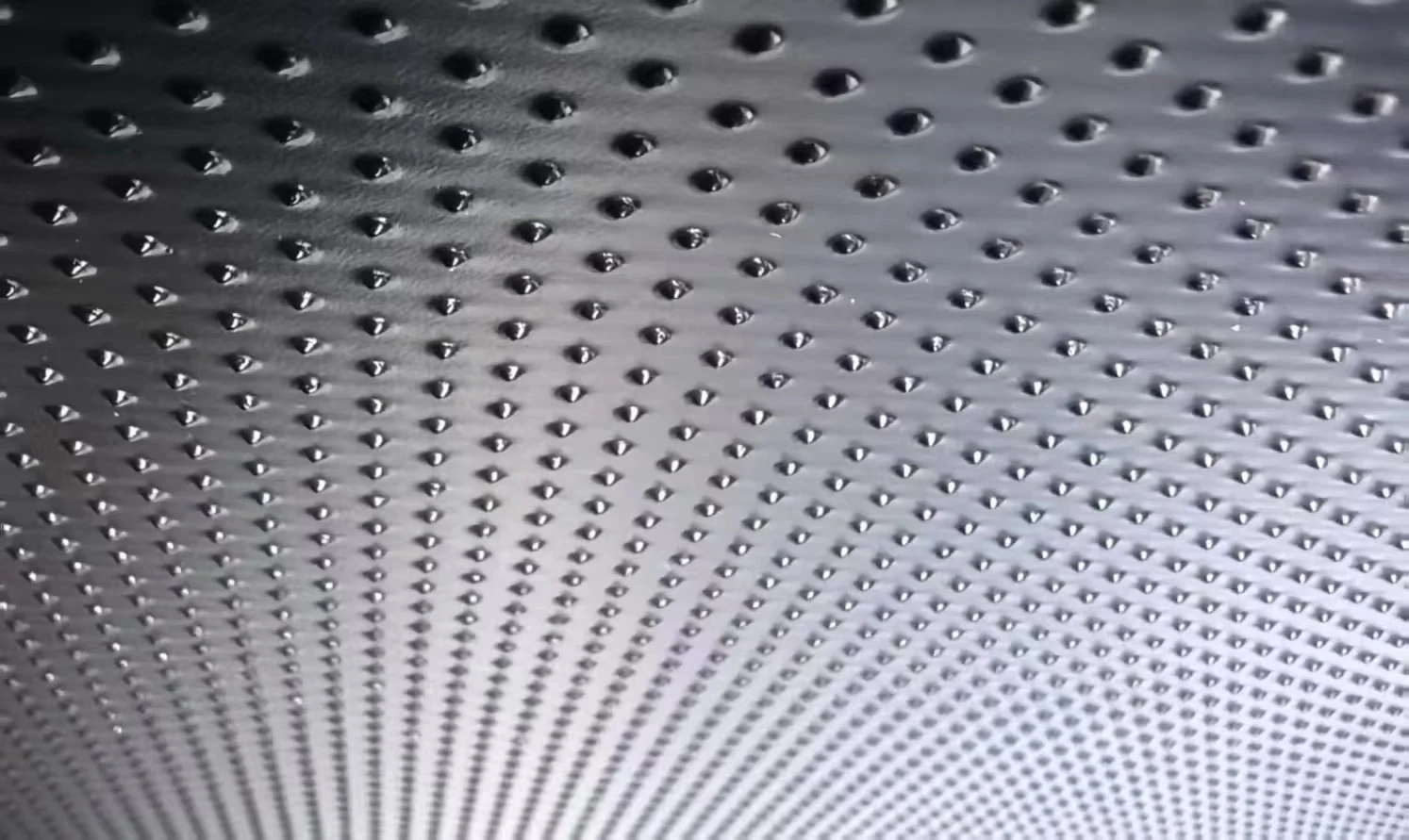
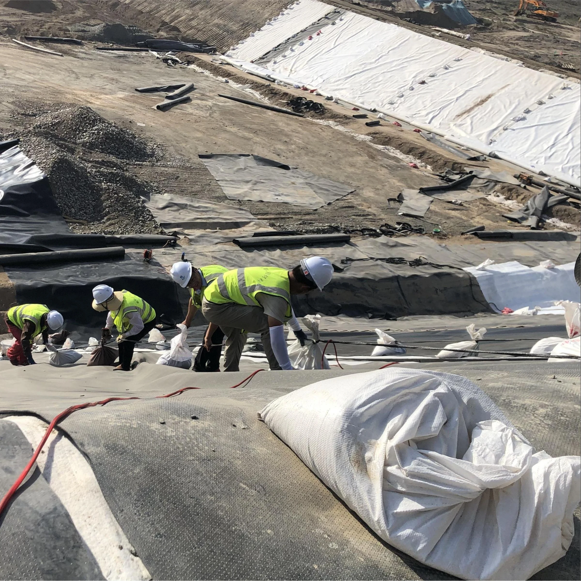
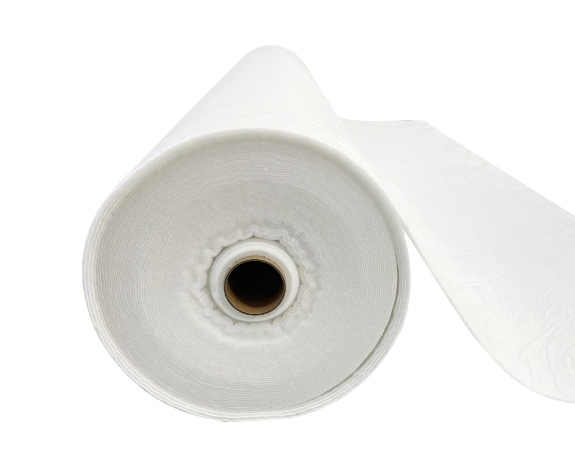

A methane barrier for a biogas digester is a complete containment system, not just a low-permeability sheet. Material permeation, seams, penetrations, anchors, cover movement and pressure controls all affect performance. A thicker membrane cannot compensate for a defective connection or an inadequately designed gas-handling system.
EPA describes biogas as typically containing about 50%–75% methane, together with carbon dioxide, water vapor, hydrogen sulfide and other constituents. Actual composition varies. Use measured gas and condensate conditions when selecting the barrier and its seals.
Gas permeability: compare the same property and conditions
Distinguish three measurements: gas transmission rate through a specimen, permeance under a stated pressure difference, and permeability normalized by thickness for a suitable homogeneous material. They have different units and cannot be compared as interchangeable numbers.
ASTM D1434-23 addresses steady-state gas transmission through plastic film and sheeting. The method’s limitations include sensitivity to material and test conditions; it does not test the integrity of field seams. A dry, single-gas laboratory result therefore needs assessment before it represents a warm, moist biogas mixture or a finished cover.
| Report item | Why it matters |
|---|---|
| Material identity and formulation | Polymer family alone does not identify the tested sheet, coating or reinforcement |
| Measured thickness and specimen construction | A homogeneous sheet and a multilayer reinforced cover may not use the same model |
| Gas composition and moisture condition | Pure methane and actual wet biogas are different exposures |
| Temperature and pressure basis | Permeation depends on exposure; distinguish partial pressure from total pressure |
| Units and reference volume conditions | Standard-volume and operating-volume figures require consistent conversion |
| Test method and uncertainty | Results from different procedures may not be directly comparable |
What a thickness comparison can and cannot show
For an idealized homogeneous sheet at steady state, a useful relationship is Q = P × A × Δp / t, where Q is permeation rate, P is the permeability coefficient in consistent units, A is area, Δp is the gas partial-pressure difference and t is thickness. It describes diffusion through intact material, not flow through holes.
Relative example: if formulation, temperature, area and pressure difference remain identical and P is unchanged, increasing thickness from 1.0 to 2.0 mm halves the calculated permeation rate. Increasing from 1.5 to 2.0 mm reduces it to 75% of the original value. These are model results, not measured reductions for an installed cover; changes in processing or material require actual test evidence.
Thickness also affects handling, stiffness, welding and structural behavior. Do not assume that material over 2.5 mm cannot be reliably welded or that heavier sheet automatically tolerates settlement better. Specify the necessary mechanical properties and a qualified joining process.
Material selection: sheet specification versus cover qualification
HDPE, LLDPE, reinforced polymer composites and elastomeric membranes may be considered in different cover arrangements. LLDPE means linear low-density polyethylene; it is not the same designation as LDPE. Compare proposed products against the assembly requirements rather than assigning every polymer a universal temperature range or service life.
GRI-GM13 addresses HDPE geomembrane manufacturing properties. GRI-GM17 addresses nonreinforced LLDPE geomembranes. Compliance with either specification does not certify a complete biogas cover, establish methane transmission for the offered product or approve operating pressure.
For a reinforced or coated fabric, request the actual laminate specification, seam requirements, gas-transmission report and connection details. Do not apply a nonreinforced HDPE tensile acceptance table to a reinforced gas-storage membrane. For elastomeric seams, use the manufacturer’s qualified joint system; an arbitrary tape width or generic adhesive cannot establish acceptance.
Assess condensate, hydrogen sulfide, cleaning agents, temperature, UV exposure and cyclic movement. There is no single hydrogen-sulfide concentration at which all EPDM suddenly fails, and no defensible universal claim that PVC covers last 5–10 years less than HDPE. Product-specific evidence and the installed conditions are necessary.
Identify leakage mechanisms before selecting a test
Separate permeation through intact sheet from leakage at seams, penetrations, damaged areas and perimeter seals. Each mechanism needs a suitable inspection or measurement method. Do not assume a fixed 80/20 distribution of defects or a fixed number of cubic metres lost per day without a survey.
Illustrative gas accounting: losing 10 standard m³/day of biogas at a measured 60% methane corresponds to 6 standard m³/day of methane, if both volumes use the same reference conditions and the composition is stated on a consistent basis. A gas concentration reading near a seam does not by itself supply the leak’s volumetric flow rate.
Define the measurement boundary for any recovery-efficiency claim. Gas production, useful gas, flare flow, venting, stored volume changes and meter uncertainty may all affect the balance. Routine inspection alone cannot substantiate a universal recovery rate above 90%.
Seam integrity and construction acceptance
For HDPE, hot-wedge seams are commonly used for suitable straight panel joints and extrusion fillet seams for qualified details and repairs. Actual temperature, pressure and travel speed depend on the material, equipment and conditions. Establish them through the approved procedure and representative trial seams.
| Test or inspection | Suitable purpose | Limit to recognize |
|---|---|---|
| Visual inspection | Identify damage, incomplete details and suspect seam areas | Cannot establish gas tightness by appearance alone |
| Air-channel testing | Check suitable dual-track seam channels | Does not measure destructive seam strength |
| Vacuum-chamber testing | Evaluate accessible seams or repairs where the method can seal | Cannot inspect an arbitrary buried seam from above the cover soil |
| Destructive seam testing | Check specified strength and failure behavior of samples | Sampling and acceptance must match the material and project plan |
| Assembly tightness testing | Evaluate the finished system under an approved test procedure | Test medium, pressure, duration and limits must suit the complete assembly |
Relevant HDPE references include ASTM D6392 for destructive seam testing and GRI-GM19a for seam acceptance properties. The material, nominal thickness, seam type and required failure criteria determine the acceptance values. Testing a few seam specimens is not the same as qualifying the gas holder’s structural capacity.
Do not apply a generic “1.5 times design pressure for 24 hours” test to a flexible cover. Excess pressure can damage the assembly. The designer and equipment supplier must specify a safe, suitable commissioning procedure, including instrumentation and acceptance limits. Temperature and changes in cover volume can also affect pressure-decay interpretation.
Flexible cover design: volume, movement and pressure
The ideal gas equation relates gas quantity, absolute pressure, temperature and volume. It does not calculate membrane shape, maximum deflection or anchor forces. Cover geometry, supports, pretension, material stiffness, creep and external loads must also be analyzed.
For gas-law calculations, pressure must be absolute. For membrane loading, the relevant input is the pressure difference across the cover. Mixing these two pressure bases can produce a large error in a low-pressure system.
Load illustration: 10 mbar equals 1 kPa. Applied uniformly over a 100 m² horizontal projected area, that pressure gives a resultant of 100 kN. This is an equilibrium calculation, not an allowable operating pressure or a uniform force at every anchor. The actual distribution depends on the assembly’s geometry and load path.
Rainwater can also create substantial load: a uniform 0.10 m water depth adds approximately 0.981 kPa, or 98.1 kN over 100 m². Local ponding and cover deformation can interact, so drainage capacity, access and failure scenarios need deliberate review.
Anchors, seals and movement clearance
Perimeter clamps, embedments, ballast arrangements or other connections must suit the cover design. A fixed 5–15 kg/m ballast value, 300 mm clearance or 200 mm flexible pipe length cannot be approved without the actual movement and load calculation. Protect contact points while avoiding unassessed changes to friction, sealing or restraint.
Where a hydraulic seal is part of an engineered system, its effective liquid head matters. For scale, 50 mm of water produces about 0.49 kPa hydrostatic pressure, while 50 mbar equals 5 kPa and corresponds to about 0.51 m of water. Groove dimensions alone do not establish usable head or pressure capacity. These conversions are explanatory, not a seal design.
Pressure control and safe maintenance
The EPA AgSTAR operator guidebook discusses pressure relief, vacuum protection where appropriate, condensate removal and flaring as parts of the biogas system. The approved design must account for blocked lines, equipment outages and changing gas production. Relief devices and controls must remain consistent with the cover and gas-handling equipment ratings.
A fixed methane concentration such as 45% is not a universal command to ignite a flare. Ignition, flame supervision, gas quality, pressure and shutdown logic must follow the approved equipment control system. Do not modify interlocks or relief settings based on a general material-selection article.
Repairs involving heat, sparks or opening the gas system require the site’s isolation, atmosphere-testing and work-permit procedures. Do not use a grinder or thermal welder on an operating gas-containing cover merely because that tool is suitable for unused sheet. EPA’s anaerobic digestion safety guidance provides background for the hazards; qualified site procedures govern the work.
Once the area is released for repair, assess substrate condition, choose compatible materials, follow the qualified repair method, retest and record the result. Surface roughness, patch dimensions and allowable thinning cannot be chosen from generic machining values. Include the repair location, cause, materials, personnel and accepted tests in the asset record.
What to request before purchasing a methane barrier
- Gas composition, condensate chemistry, temperatures and operating pressure/vacuum envelope.
- Cover arrangement, drawings, liquid levels, expected movements and environmental loads.
- Material construction, measured thickness and gas-transmission data with complete units and test conditions.
- Seam and perimeter-connection specifications, quality records and commissioning requirements.
- Defined pressure-control interfaces, inspection access, repair procedures and supplier responsibilities.
Provide these details to Jinseed for a project-specific material review. For a related polymer comparison, see HDPE versus LLDPE geomembranes. A sheet test report can support material selection; it should not be presented as certification of an entire biogas containment system or a guarantee of a particular methane recovery rate.