Geomembrane lining for seepage control (landfills, permeability coefficient ≤ 1×10⁻¹² cm/s) select HDPE;
for drainage (mine restoration) select composite geotextile; for acid and alkali resistance select HDPE with carbon black (UV resistant).
For slopes > 15°, use textured surfaces (friction coefficient 0.3-0.6);
for permafrost areas, select frost-resistant types with thickness ≥ 2.0mm.
HDPE (chemical resistant, 50-year lifespan) is mainstream;
LDPE (good flexibility, thickness 0.5-1.5mm) is suitable for low temperatures.
Landfills use 1.5-3.0mm (tensile strength ≥ 25MPa);
roadbeds use 0.5-1.0mm (elongation at break ≥ 700%).
Installation technology: dual-track hot-melt welding (temperature 200-300℃, speed 0.5-1.5m/min), weld peel test ≥ 30N/mm;
after completion, water injection leak test (24-hour drop ≤ 5cm).
Application Requirements
For scenarios involving long-term contact with strong acid and alkali liquids with pH values between 2 and 12, High-Density Polyethylene (HDPE) complying with the ASTM D7957 standard is the preferred choice, as its chemical degradation resistance is superior to other polymers.
If the project foundation carries a risk of differential settlement, Linear Low-Density Polyethylene (LLDPE), with an elongation at break exceeding 800% (ASTM D6693), can effectively prevent stress cracking.
For steep slopes with a gradient greater than 3:1, textured geomembranes must be used to increase the interface friction angle to above 20° to prevent soil landslides.
Topography and Physical Stress
Interface Friction Angle
Smooth Geomembrane has a slick surface, and its interface friction angle with clay or geotextiles is typically very low, only 8° to 12°.
Textured Geomembrane forms uneven textures on the membrane surface through co-extrusion or spray-on processes, significantly increasing mechanical interlocking force.
- Friction Angle Enhancement: The interface friction angle of high-quality textured HDPE geomembranes can reach 20° to 30°, depending on the type of contact material (e.g., non-woven geotextile vs. sand).
- Asperity Height: According to the GRI-GM13 standard, the asperity height of textured geomembranes is a hard indicator for measuring friction performance. Generally, the asperity height is required to reach at least 0.25 mm (10 mil); for high steep slopes (e.g., 2:1 gradient), materials with custom asperity heights exceeding 0.40 mm (16 mil) are often required.
| Interface Combination | Smooth Geomembrane Friction Angle (Typical) | Textured Geomembrane Friction Angle (Typical) | Factor of Safety (FS) Impact |
|---|---|---|---|
| Geomembrane / Compacted Clay | 10° – 14° | 18° – 26° | Textured can increase FS by more than 1.5 times |
| Geomembrane / Non-woven Geotextile | 8° – 11° | 22° – 29° | Textured provides sufficient interlocking to prevent geotextile sliding |
| Geomembrane / Sand Layer | 18° – 22° | 28° – 35° | Textured is suitable for steep slope designs |
Engineering designs cannot rely on general data tables; ASTM D5321 large-scale direct shear tests must be conducted using site-specific soil and selected geosynthetics.
Tests must simulate the maximum normal stress on-site (Normal Load);
for example, in bottom liner systems, the waste mass may generate vertical pressures exceeding 500 kPa.
Foundation Settlement and Materials
1. Uniaxial Tension vs. Multi-axial Tension
- Uniaxial Data Pitfall: Most technical data sheets provide “Elongation at Break” based on the ASTM D6693 uniaxial tension test. While HDPE’s uniaxial elongation at break can reach 700%, its yield elongation is only around 12%. Once deformation exceeds the yield point, the microstructure of HDPE undergoes irreversible changes, the material thins, and Environmental Stress Crack Resistance (ESCR) is essentially lost.
- Multi-axial Performance (ASTM D5617): In areas of differential settlement (such as karst topography or soft soil roadbeds), the geomembrane is subjected to “bulging” stress. The ASTM D5617 test simulates this condition.
- HDPE Performance: Due to high crystallinity (approx. 50-60%) and high rigidity, its multi-axial break elongation is typically between 15% – 20%.
- LLDPE Performance: Due to its molecular side-chain structure and lower crystallinity, LLDPE has no obvious yield point, and its multi-axial break elongation can typically remain above 100%. Therefore, LLDPE is a safer choice for areas where predicted settlement exceeds 5% – 8%.
2. “Arching Effect” and Local Strain
In landfill closure projects, the degradation of waste mass leads to the formation of voids.
The overlying soil layer may form a “soil arch,” but when it eventually collapses, it instantly exerts impact and tension on the geomembrane.
Design codes typically limit the allowable strain for HDPE to within 3% to ensure long-term safety;
For LLDPE, this limit can be relaxed to 8% – 10%.
Substrate Roughness
1. Allowable Particle Diameter
- 60 mil (1.5 mm) Geomembrane: Generally requires that the maximum particle diameter of the substrate soil does not exceed 12 mm (0.5 inch) and must be rounded, non-angular gravel.
- 80 mil (2.0 mm) Geomembrane: Allowable particle diameter can be slightly relaxed to 25 mm (1 inch), but the shape of the rock still needs evaluation.
2. Role of Geotextile Cushion Layer
When the terrain contains a large amount of crushed stone that is difficult to completely remove, non-woven needle-punched geotextile must be laid under the geomembrane as a protective layer.
- Quality Requirements: Protection layer specifications are usually determined by the CBR Puncture Strength Test (ASTM D6241) or the Pin Puncture Test (ASTM D4833). For substrates containing 20mm crushed stone, geotextiles with a weight of above 500 g/m² (14.7 oz/yd²) are typically required to provide sufficient cushioning.
- Geocomposite: In some scenarios, selecting factory-prefabricated geomembrane/geotextile composites (Geocomposites) can provide more stable peel strength and prevent interlayer sliding during on-site laying.
Thermal Expansion and Contraction
1. Coefficient of Linear Thermal Expansion (CLTE)
The coefficient of linear thermal expansion for polyethylene materials is approximately $1.2 \times 10^{-4} \text{ m/m}^{\circ}\text{C}$.
In a typical day-night cycle with a temperature difference of 30°C, a 100-meter long geomembrane can experience a change in length of:
$$ \Delta L = 100 \text{ m} \times 30^{\circ}\text{C} \times (1.2 \times 10^{-4}) = 0.36 \text{ m} $$
That is, a 36 cm expansion/contraction.
2. “Trampolining” Effect
- Phenomenon: If laying and anchoring are performed during high-temperature periods (when the membrane body is expanded and relaxed), the membrane will shrink drastically when temperatures drop sharply at night. At the toe of the slope, the shrunken geomembrane will pull away from the substrate, forming a trampoline-like structure.
- Consequences: The suspended geomembrane will bear enormous tension during subsequent waste filling or water injection, making it highly susceptible to tearing at the welds.
- Countermeasures:
- Thermal Compensation: Construction personnel must calculate the reserved “slack” based on the temperature during laying.
- Construction Window: Node welding should only be performed when the ambient temperature is close to the project’s average service temperature (usually early morning or evening).
In high-wind areas, peripheral anchoring alone is insufficient; a ballast system composed of sandbags must be set on the membrane surface.
Sandbag spacing and weight should be calculated based on local maximum wind speeds.
For example, in areas with wind speeds reaching 90 km/h, an array of 20 kg sandbags might be required every 5 meters to suppress membrane uplift.
Climate Exposure and UV Resistance
Carbon Black
Carbon Black, as an efficient UV absorber, converts light energy into heat, preventing it from damaging the polymer matrix.
Not all black plastics are UV resistant.
- Content Standard: The industry-recognized carbon black addition amount is 2.0% to 3.0% (by weight). Less than 2% cannot provide sufficient coverage density, while more than 3% destroys polymer continuity, making the material brittle and reducing physical strength.
- Particle Size: Effective carbon black particle diameters must be between 22 nm and 25 nm. Large-particle carbon black (such as some cheap masterbatches) cannot effectively scatter UV light.
Carbon black must be uniformly dispersed within the polymer matrix.
If poorly mixed, the resulting carbon black agglomerates not only fail to protect against UV but also become defect points for stress concentration.
- ASTM D5596 Test: This standard evaluates carbon black dispersion via microscope.
- Category 1: Best, uniform particle distribution.
- Category 2: Acceptable.
- Category 3: Rejected. Membranes with this rating have visible clumps; these areas will rapidly perforate under sunlight.
Polymer Types
| Material Type | Base UV Resistance | Protection Mechanism | Typical Exposed Lifespan Expectancy (Mid-latitudes) |
|---|---|---|---|
| PVC (Polyvinyl Chloride) | Very Poor | Small amount of stabilizers only | < 1 year (Hardening, cracking) |
| Untreated PE | Poor | None | 1 – 2 years |
| HDPE (with Carbon Black) | Excellent | Physical shielding (Carbon Black) | > 20 years |
| LLDPE (with Carbon Black) | Good | Physical shielding (Carbon Black) | 15 – 20 years |
| fPP (Flexible Polypropylene) | Medium/Good | Chemical quenching (HALS) | 10 – 20 years (depending on formula) |
| EPDM / CSPE | Superior | Saturated and stable polymer backbone | > 30 years |
- PVC’s Fatal Weakness: PVC relies on liquid plasticizers to maintain flexibility. Under the combined action of UV and heat, plasticizers accelerate migration and volatilization, leading to volume shrinkage, hardening like slate, and eventual crazing. Therefore, PVC is limited to underground burial projects.
- EPDM and CSPE Strengths: These two synthetic rubber materials have very stable backbone structures (saturated bonds) and are insensitive to UV. CSPE (Chlorosulfonated Polyethylene) was once widely used for floating covers in drinking water reservoirs, with over 30 years of measured service records.
Oxidation Induction Time
1. Standard OIT (Std-OIT, ASTM D3895) vs. High-Pressure OIT (HP-OIT, ASTM D5885)
- Std-OIT: Measured at 200°C. Suitable for monitoring standard antioxidants. GRI-GM13 requires the standard OIT of HDPE to be at least 100 minutes.
- HP-OIT: Measured at 150°C and high-pressure oxygen. This is critical for materials containing HALS (Hindered Amine Light Stabilizers). HALS fails at the 200°C high temperature of Std-OIT, leading to falsely low test results. Therefore, for fPP or light-colored geomembranes, HP-OIT data must be referenced; GRI-GM13 requires its value to be at least 400 minutes.
2. UV Weatherometer Test
According to ASTM D7238, samples are placed in a fluorescent UV lamp box and cyclically exposed at high temperatures.
- Passing Criterion: After 1600 hours of accelerated aging, the HP-OIT retention rate must be above 50%. This indicates that less than half of the antioxidants in the material have been consumed, leaving enough “fuel” to maintain use in subsequent years.
According to the GRI-GM13 specification, HDPE geomembranes used in exposed environments must have 2.0% – 3.0% fine-particle carbon black added to block the energy of UV photons with wavelengths between 290-400 nm.
For flexible polypropylene (fPP) or LLDPE relying on Hindered Amine Light Stabilizers (HALS) for protection, they must pass the ASTM D7238 UV Weatherometer test and maintain an initial value of over 400 minutes in the High-Pressure Oxidation Induction Time (HP-OIT, ASTM D5885) test.
PVC materials without UV resistance additives will develop micro-cracks and lose mechanical strength within 6 months under a radiation intensity of 150 kLy (kilo-Langley).
Site Condition
If the substrate contains sharp particles with a diameter greater than 25mm, geomembranes with a puncture resistance higher than 400N must be selected, or used in conjunction with a non-woven geotextile cushion of over 500g/m².
For projects with slopes steeper than 3:1 (18.4°), the interface friction angle of smooth HDPE is insufficient to maintain stability; textured geomembranes must be used to increase the friction angle to the 20°-30° range.
If the predicted foundation settlement rate exceeds 10% (such as landfill capping), standard HDPE will face stress cracking risks due to its yield elongation being only 12%;
LLDPE material with elongation at break up to 800% and no yield point should be used instead.
Substrate Flatness and Particle Size
Particle Geometry & Limits
- Angular: Sharp particle edges, similar to crushed stone chips. Such particles pose an immediate puncture threat to the geomembrane. For standard 1.5mm HDPE geomembranes, the maximum allowable size for angular particles is typically limited to below 6mm.
- Sub-rounded: Particle edges are worn and relatively rounded. Such particles mainly generate pressure stress rather than punctures. Allowable sizes can generally be relaxed to 25mm.
Table of Geomembrane Thickness and Protection Layer Recommendations under Different Substrate Particles
| Max Particle Size | Particle Morphology | Min Recommended Membrane Thickness (HDPE) | Required Protective Measures |
|---|---|---|---|
| < 5mm | Sandy/Silty | 1.0mm (40 mil) | No extra protection, direct laying |
| 6mm – 12mm | Sub-rounded | 1.5mm (60 mil) | 200g/m² geotextile recommended |
| 12mm – 25mm | Angular | 2.0mm (80 mil) | Must use 400g/m² geotextile |
| 25mm – 50mm | Any Morphology | 2.5mm (100 mil) | Must use 600g/m² – 800g/m² geotextile or GCL |
| > 50mm | Any Morphology | Not recommended | Must replace with 150mm sand cushion |
Cushioning Design
Relationship between Weight and Protection:
Many projects erroneously use lightweight geotextiles of 150g/m² – 200g/m².
At water pressures of over 20 meters, this thickness will be compressed as thin as paper, completely losing the ability to cushion sharp objects.
- For rough substrates, the starting specification should be 400g/m² (12 oz/yd²).
- For substrates containing sharp rock fragments, the specification should be increased to 540g/m² (16 oz/yd²) to 800g/m² (24 oz/yd²).
Polymer Type Selection:
- Virgin PP (Polypropylene): The most common choice, with good acid and alkali resistance.
- Polyester (PET): If the substrate soil contains high concentrations of alkaline substances (pH > 10), PET will undergo hydrolytic degradation, causing the protective layer to disappear after a few years. In such high-alkaline soil environments (such as bauxite tailings ponds), polypropylene materials must be used.
Compaction & Void Management
Drum Effect:
When a geomembrane spans a void with a 1-meter diameter, the water pressure above (e.g., 10m water depth, i.e., 100 kPa pressure) will force the geomembrane to deform downwards.
- Limitations of HDPE: HDPE is a semi-crystalline material with a yield elongation of only 12%-15%. Once deformation exceeds this limit, the material enters the plastic deformation stage, the thickness decreases sharply, and Environmental Stress Crack Resistance (ESCR) drops to nearly zero.
- Compaction Standards: Construction specifications require substrate soil to be compacted in layers, with each layer not exceeding 300mm and compaction reaching 95% of the Standard Proctor Density.
- Moisture Content Control: The soil moisture content during compaction should be controlled within ±2% of the optimum moisture content. Being too dry leads to loose soil, while being too wet leads to shrinkage cracking after drying.
Alternatives
On some extremely rough or fractured rock substrates, relying solely on geotextiles cannot provide sufficient flatness.
In such cases, using a Geosynthetic Clay Liner (GCL) as the secondary layer of a composite liner system is an efficient solution.
GCL usually consists of two layers of geotextiles sandwiching natural sodium bentonite, with a thickness of approximately 6mm – 10mm.
- Self-healing and Filling: The bentonite in GCL expands upon contact with water, physically filling micro-cracks and irregularities in the substrate rock, providing a uniform, dense hydraulic base for the geomembrane above.
- Seepage Rate Reduction: This “membrane + GCL” composite structure can reduce the theoretical seepage rate through geomembrane pinholes by 3 to 4 orders of magnitude. According to calculations using the Giroud-Badu formula, the anti-seepage effect of a composite liner is far superior to a single layer of membrane because GCL blocks lateral flow under the membrane.
Before the arrival and laying of the geomembrane, acceptance of substrate flatness must be performed according to quantified standards rather than just visual inspection.
- Proof Rolling: Use a heavy roller or a fully loaded truck to drive over the substrate. Tire track depth must not exceed 12mm, and no obvious “pumping” (springy soil) phenomenon should occur.
- Straightedge Testing: Place a 3-meter long straightedge on the substrate surface; the maximum gap (depression) in any direction must not exceed 25mm.
- Rock Content Verification: Randomly sample 1 square meter within every 1000 square meter area, sieve the top 50mm of soil, and confirm that the percentage of particles >12mm complies with design specifications.
By precisely controlling the above technical dimensions, the failure rate of the anti-seepage system due to substrate issues can be controlled to below 1%.
Slope Stability and Interface Friction
Texturing Methods
- Co-extruded: Recommended.
- During the three-layer co-extrusion process of geomembrane production, foaming agents or specific resins are added to the outer layer, allowing the surface to naturally form a rough texture.
- Advantages: The rough layer is integral to the membrane body, so there is no risk of peeling. Physical properties are balanced.
- Spray-on: Should be evaluated cautiously.
- Molten polyethylene particles are sprayed onto the surface of an already produced smooth membrane.
- Risk: Under high shear stress, the sprayed particles may detach from the membrane body (Rub-off effect), causing an instantaneous drop in the friction coefficient and triggering landslides. If particles can be rubbed off with slight force by hand on-site, the material absolutely cannot be used on steep slopes.
- Structured/Embossed:
- Textured rollers are used to press regular patterns while in a molten state.
- Advantages: Texture consistency is extremely high, usually used for specific drainage designs, but the friction angle may be slightly lower than disorganized co-extruded textured surfaces.
Direct Shear Testing
ASTM D5321 Standard Test Protocol:
- Material-Specific Testing: Lab tests must be conducted using actual soil samples excavated from the project site and geosynthetic samples that will be used in the project.
- Normal Stress Loading: The normal stress applied during the test must cover the maximum expected soil cover depth pressure on-site. For example, if the landfill depth is 30 meters, the test must include normal stress conditions of at least 300-400 kPa.
- Large-Displacement Shear: Many materials exhibit high “Peak Strength” at small displacements but degrade to “Residual Strength” after a certain displacement (e.g., 50mm – 100mm).
- Design Principle: Considering installation disturbances and long-term creep, conservative designs are usually calculated based on residual strength or large-displacement strength rather than peak strength.
Slope and Materials
- Slope < 4:1 (14°):
- This is a relatively safe zone. If the overlying soil layer is very thin, smooth HDPE might be feasible. However, if GCL is used, textured membranes are still recommended because the internal shear strength of GCL is limited.
- Slope 3:1 (18.4°) to 4:1:
- Transition Zone. Must be calculated. If smooth membrane is used, the Factor of Safety (FS) is difficult to reach 1.5. This is usually the starting point for introducing textured geomembranes.
- Single-sided vs. Double-sided Textured: If there is a flat substrate under the membrane and soil cover over it, single-sided textured (textured side up) can be used. However, for slip resistance and to facilitate worker movement, double-sided textured is usually preferred.
- Slope 2.5:1 (21.8°) to 3:1:
- Mandatory Textured Zone. Whether it is HDPE or LLDPE, double-sided textured products must be used. At this point, membrane friction alone may be near its limit, and high-strength geogrids may need to be introduced to share the downslope force of the soil.
- Slope > 2.5:1:
- Relying solely on the surface friction of the geomembrane is no longer sufficient to maintain stability. Specialized reinforced soil engineering designs must be conducted, or the slope geometry must be changed (e.g., adding benches).
A geomembrane on a slope is like a bedsheet hanging on a wall; gravity constantly pulls it down.
The anchor trench is the last line of defense preventing the geomembrane from sliding down.
When calculating anchor trench depth and backfill ballast, it must be ensured that the tension on the membrane is less than 50% of its yield strength.
Typical anchor trenches are at least 1.0m – 1.5m away from the slope crest edge (to prevent edge collapse), and the trench cross-section is usually 0.5m x 0.5m, in a U or V shape.
Material Type
The polymer substrate HDPE (High-Density Polyethylene) is the industry standard, with a density greater than 0.940 g/cc and the strongest chemical resistance, suitable for environments with pH 2-12;
LLDPE (Linear Low-Density Polyethylene) sacrifices some rigidity for 12-15% higher multi-axial elongation, better adapting to foundation settlement;
PVC (Polyvinyl Chloride) can be factory-prefabricated into large panels of over 2,000 square meters, reducing on-site welding, but usually requires soil cover protection;
EPDM (Ethylene Propylene Diene Monomer) possesses wide-temperature weather resistance from -45°C to 120°C;
fPP (Flexible Polypropylene) performs better in high-temperature industrial wastewater.
Selection should refer to ASTM or GRI specifications.
HDPE
Chemical Resistance Mechanism
- pH Tolerance Range: Whether it is highly concentrated sulfuric acid (pH < 2) in mining leachates or caustic soda solutions (pH > 12) in alumina production, HDPE maintains its polymer backbone without degradation.
- Swelling Phenomenon: When in contact with high concentrations of chlorinated solvents or aromatic hydrocarbons (such as benzene, toluene), HDPE does not dissolve but undergoes physical swelling. Solvent molecules enter the amorphous regions of the polymer, causing a weight increase and temporary loss of mechanical strength. Experimental data shows that within a 10% weight increase range, this physical change is usually reversible; once the pollutant is removed, material properties can recover.
- Oxidative Attack: Despite its strong chemical resistance, HDPE is sensitive to strong oxidizers (such as high-concentration chromic acid, nitric acid, or hypochlorites). These chemicals consume the antioxidant package in the material; once antioxidants are depleted, the polymer chains undergo oxidative scission. Therefore, monitoring HP-OIT (High-Pressure Oxidation Induction Time, ASTM D5885) is the only reliable means to evaluate its remaining life in oxidative environments.
Cracking Resistance
Environmental Stress Cracking is not chemical corrosion but brittle fracture caused by tension below the yield point in conjunction with surfactants (such as detergents or organic matter in leachate).
- Failure Mechanism: The crystalline regions of polyethylene are very strong, but the tie molecules connecting the crystals are relatively weak. When subjected to continuous tension, if surfactants are present in the environment, these tie molecules will gradually “untie” or break, forming micro-cracks that eventually lead to visible fractures.
- Evolution of Testing Standards: The early ASTM D1693 (bent-strip test) has been phased out due to large errors. Currently, the industry gold standard is ASTM D5397 (Notched Constant Tensile Load test, NCTL).
- Data Threshold: According to the GRI GM13 specification, the NCTL failure time for HDPE must exceed 300 hours. However, in high-risk projects (such as deep landfills with enormous bottom pressure), engineers usually require this indicator to reach 500 hours or even higher. This requires resin suppliers to use bimodal or hexene-copolymer technology to increase the number and entanglement of tie molecules.
Texturing and Friction Angle
Smooth HDPE surfaces have a very low friction coefficient (approx. 0.10 – 0.12), which is a major landslide risk in slope applications.
- Manufacturing Process Differences:
- Co-extrusion: During production, a layer of polyethylene containing high-concentration nitrogen foaming agent is extruded onto the membrane surface via a specialized die. The bursting bubbles form a rough surface. This process has good integrity, and the textured layer is not easily peeled off.
- Impingement (Spray-on): Molten polyethylene particles are sprayed onto the surface of an already formed hot membrane. This method results in extremely high surface roughness (Asperity Height can reach over 0.5mm), providing very strong physical interlocking force.
- Friction Angle Enhancement: Using textured HDPE can increase the interface friction angle between the geomembrane and geotextiles or soil from 8-10 degrees to 20-30 degrees. When designing landfill slopes steeper than 3:1, this parameter determines the physical stability of the system.
Durability and Antioxidant Package
- Role of Carbon Black: Standards stipulate a carbon black content of 2.0% – 3.0%. Carbon black particles must reach nanoscale dispersion (ASTM D5596 stipulates dispersion grades must be Category 1 or 2). These black particles act like countless tiny parasols, absorbing and dissipating UV energy to prevent polymer chain scission.
- Antioxidant Depletion Model: The aging of geomembranes is divided into three stages:
- Antioxidant Depletion Period: No change in physical properties, only the internal stabilizers are being consumed.
- Induction Period: Stabilizers are exhausted, and the polymer begins to oxidize slowly, but macro properties are still maintained.
- Performance Degradation Period: Physical indicators drop precipitously.
Current tests (such as oven aging ASTM D5721 + OIT tests) aim to predict the duration of the first stage. High-quality HDPE, in an 85°C standard laboratory accelerated aging test, can maintain an OIT retention rate of over 55% after 90 days, suggesting that actual engineering lifespans often exceed 100 years (under soil cover conditions).
Material Specification Reference Table (Based on GRI GM13)
| Performance Indicator | Test Method | 1.50 mm (60 mil) Nominal Value | 2.00 mm (80 mil) Nominal Value | Remarks |
|---|---|---|---|---|
| Density | ASTM D792 | ≥ 0.940 g/cc | ≥ 0.940 g/cc | Minimum value |
| Tensile Strength at Yield | ASTM D6693 | ≥ 22 kN/m | ≥ 29 kN/m | Measures material hardness |
| Tensile Strength at Break | ASTM D6693 | ≥ 40 kN/m | ≥ 53 kN/m | Measures ultimate strength |
| Yield Elongation | ASTM D6693 | ≥ 12% | ≥ 12% | Rigidity indicator |
| Elongation at Break | ASTM D6693 | ≥ 700% | ≥ 700% | Ductility indicator |
| Puncture Resistance | ASTM D4833 | ≥ 400 N | ≥ 530 N | Resists sharp objects |
| Tear Resistance | ASTM D1004 | ≥ 187 N | ≥ 249 N | Resists tear propagation |
| Carbon Black Content | ASTM D1603 | 2.0 – 3.0% | 2.0 – 3.0% | UV Protection |
| Stress Cracking (SP-NCTL) | ASTM D5397 | ≥ 300 hours | ≥ 300 hours | Long-term durability |
HDPE (High-Density Polyethylene) is the benchmark material for modern anti-seepage engineering, with a density that must reach or exceed 0.940 g/cm³.
Thanks to its high crystallinity of 50% to 80%, this material demonstrates excellent barrier capabilities against strong acids and alkalis with pH values ranging from 2 to 12, as well as hydrocarbons and heavy metal ions.
HDPE complying with the GRI GM13 international specification typically has a puncture resistance exceeding 400 N (1.5mm thickness benchmark), and its carbon black content must be strictly controlled between 2.0% and 3.0% to ensure a service life of over 20 years in exposed environments.
LLDPE
Uniaxial Testing
- Absence of Yield Point: HDPE shows a distinct yield point (necking) when stretched to 12-13%, followed by a drop in strength as it enters the necking extension phase. LLDPE typically has no distinct yield point on its tensile curve. Its stress increases continuously with strain until failure. LLDPE maintains growth in load-bearing capacity throughout the entire deformation process.
- Multi-axial Burst Data: When using ASTM D5617 for multi-axial tension testing, the material is fixed like a drumhead and inflated. HDPE usually bursts at low bulging heights due to excessive rigidity, with multi-axial elongation often below 50%. In contrast, LLDPE can undergo massive plastic deformation like a balloon, with multi-axial elongation easily exceeding 100% or even reaching 150%. This characteristic allows LLDPE to disperse stress through local thinning when encountering protruding rocks or localized collapse, rather than concentrating stress and puncturing.
Settlement Adaptation
A landfill mass is a dynamic environment; as organic matter undergoes anaerobic decomposition, the mass volume shrinks over time, and due to uneven waste composition, settlement is often localized and severe.
- Elimination of the Bridging Effect: If high-rigidity HDPE is used, the membrane body may “bridge” over hollows when the soil beneath it sinks. Under the heavy pressure of overlying soil, the membrane undergoes extreme tension at the suspended sections, leading to brittle failure once the yield point is exceeded. LLDPE’s low modulus allows it to conform to the profile of the depression, always staying tight against the substrate and minimizing membrane tension.
- Natural Advantage in Environmental Stress Crack Resistance (ESCR): Due to the high entanglement of LLDPE molecular chains and low crystallinity, internal stress is extremely difficult to accumulate within the material. In ASTM D5397 tests, LLDPE often shows no failure after 1500 hours, far exceeding the 300-500 hours required for HDPE specifications. This is crucial for landfill closure systems that are under long-term tension.
Construction Characteristics
- Flatness during Hot Laying: HDPE suffers from severe thermal expansion, making it prone to waves. While LLDPE has a similar coefficient of thermal expansion, its low modulus makes the material “softer,” and its own weight more easily overcomes uplift caused by thermal stress. Consequently, its lay-flat characteristics after installation are significantly better than HDPE’s.
- Adjustment of Welding Parameters: The melt strength of LLDPE is lower than that of HDPE. During hot-wedge welding, if the temperature is too high or the pressure too great, it is easy to cause excessive melt squeeze-out, leading to thinning of the weld.
- Temperature Setting: Usually 20-30°C lower than HDPE, set between 320°C – 370°C.
- Speed Coordination: Requires more precise speed control to prevent burn-through.
- Peel Strength Requirements: According to GRI GM17, the weld peel resistance for 1.5mm LLDPE is required to be 394 N/m (hot wedge) and 350 N/m (extrusion), which is numerically lower than HDPE because the tensile strength of the material itself is lower.
Slope Stability
- Friction Coefficient: The interface friction angle between textured LLDPE and non-woven geotextiles can typically reach 25° – 30°.
- Process Impact: This is similar to HDPE, divided into co-extrusion and spray-on. However, on LLDPE, the “interlocking” effect of the texture is often better due to the softness of the substrate itself, providing greater interlocking force.
- Reduction in Tensile Strength: It is worth noting that after texturing, the elongation at break for LLDPE will decrease. Engineers need to consult specific parameters for textured materials in GRI GM17 (for example, the elongation at break requirement drops from 800% for smooth to 250% for textured) during design to ensure compliance.
Material Specification Reference Table (Based on GRI GM17)
| Performance Indicator | Test Method | 1.00 mm (40 mil) Nominal Value | 1.50 mm (60 mil) Nominal Value | Remarks |
|---|---|---|---|---|
| Density | ASTM D792 | ≤ 0.939 g/cc | ≤ 0.939 g/cc | Maximum value limit |
| Tensile Strength at Break | ASTM D6693 | ≥ 27 kN/m | ≥ 40 kN/m | Break only, no yield |
| Elongation at Break | ASTM D6693 | ≥ 800% | ≥ 800% | Gauge length 50mm |
| 2% Secant Modulus | ASTM D5323 | ≤ 480 MPa | ≤ 480 MPa | Measures softness; lower is softer |
| Puncture Resistance | ASTM D4833 | ≥ 250 N | ≥ 370 N | Lower than HDPE of same thickness |
| Tear Resistance | ASTM D1004 | ≥ 100 N | ≥ 146 N | Resists tear propagation |
| Multi-axial Tensile Strain | ASTM D5617 | ≥ 30% (Old standard) | Actual often >100% | Measures 3D deformation |
| Carbon Black Content | ASTM D1603 | 2.0 – 3.0% | 2.0 – 3.0% | UV Protection |
Linear Low-Density Polyethylene (LLDPE) is a polymer that forms a large number of short side chains on the main chain through the introduction of co-monomers (such as butene, hexene, or octene), with its density strictly controlled below 0.939 g/cc (typically 0.915-0.925 g/cc).
This low-crystallinity structure gives the material an extremely low 2% Secant Modulus (approx. 400-500 MPa, only half that of HDPE), providing it with excellent flexibility.
In the ASTM D5617 multi-axial tension test, LLDPE exhibits a break strain exceeding 150%, far surpassing HDPE’s performance.
As a material covered by the GRI GM17 standard, it is specifically designed for geological environments with differential settlement, such as landfill closure cover systems.
Because its internal stress is extremely low, it effectively eliminates the risk of tearing caused by the “bridging effect,” and due to its high proportion of amorphous regions, its natural ESCR value typically exceeds 1500 hours.
PVC
Factory Prefabrication
PVC is the only geomembrane material that can be prefabricated on a large scale in a factory.
- Panel Size: Polyethylene membranes are usually transported to the site in 7-8 meter wide rolls, with every seam requiring welding in an open-air environment. Conversely, PVC membranes can be joined from original rolls into massive panels in a controlled factory setting. Standard prefabricated panels can weigh 1.8 – 2.0 tons and have an unfolded area of 1,500 – 2,500 square meters.
- Accordion Folding: These massive panels are not rolled but “accordion folded” and packed on pallets. At the construction site, workers simply place the pallet in a specific location, pull it open in one direction mechanically or manually, and then unfold it to both sides.
- Installation Speed: A skilled 4-person crew can lay over 10,000 square meters of PVC membrane per day on a prepared substrate. Since on-site seams only account for 5% – 10% of the total seam length, the risk of welding failure due to weather (rain, wind, dust) is reduced geometrically.
Mechanical Performance
- Stress-Strain Curve: PVC shows no distinct yield point in tensile tests. Its stress increases linearly with strain until failure. According to ASTM D882 (D6693 is not used as PVC is very soft), its elongation at break is typically between 380% – 450%.
- Biaxial Adaptability: Laboratory hydrostatic burst tests (ASTM D751) show that when subjected to three-dimensional pressure, PVC can expand uniformly like a balloon. This characteristic allows it to disperse stress through local thinning when responding to substrate collapse or covering sharp objects, rather than concentrating stress and tearing.
- Interface Friction: PVC surfaces naturally possess slight tackiness. Even smooth PVC can achieve an interface friction angle of 24° – 28° with soil or non-woven fabrics. Most applications do not require specialized texturing like polyethylene to meet slope stability requirements. For steeper slopes (e.g., 2.5:1), a “file finish” surface produced by calendering can further increase the friction coefficient.
Fatal Weakness
The biggest engineering consideration when choosing PVC is its aging mechanism.
Unlike the oxidative degradation of polyethylene, PVC aging is primarily a physical process—the loss of plasticizers.
- Migration Mechanisms:
- Volatility: Under high temperatures or windy conditions, plasticizer molecules evaporate from the surface.
- Extraction: When in contact with liquids (especially oils, solvents), plasticizers are dissolved and pulled out.
- Microbial Degradation: Bacteria in the soil may consume certain types of plasticizers as a food source.
- Consequences: As plasticizers are lost, the glass transition temperature (Tg) of the PVC membrane rises, and the material gradually reverts to rigid PVC, shrinking, becoming brittle, and eventually shattering like glass under tension.
- Engineering Countermeasure (Burial Principle): To block these aging pathways, standard PVC geomembranes must be used in buried applications. A soil cover not only isolates the material from UV and high temperatures but also inhibits plasticizer volatilization. In buried environments, excavated 30-year-old PVC samples often still maintain good flexibility.
- Special Formulations: If exposed use is mandatory (such as on certain roofs or temporary ponds), PVC modified with high-molecular-weight plasticizers (like Elvaloy® KEE) or special UV-resistant materials must be selected, but these belong to specialized categories.
Connection Technology
PVC joining methods provide high fault tolerance and ease of repair.
- Solvent Welding (Chemical Fusion): This is a connection method unique to PVC. A solvent containing dissolved PVC resin (similar to glue but essentially a dissolving agent) is applied to overlapping surfaces; after compaction, the two layers of membrane fuse into one at the molecular level.
- Advantages: Does not require expensive heavy welding equipment or electricity, making it ideal for narrow spaces, sealing pipe penetrations, and later repairs of damage.
- Disadvantages: Heavily dependent on the worker’s skill, and solvent volatilization is strongly affected by ambient temperature.
- Hot Air/Hot Wedge Welding: Modern large-scale projects prefer hot-wedge welders. Unlike welding PE, the temperature window for welding PVC is narrower (approx. 400°C – 450°C), and steel or silicone rollers must be used for compression.
- Radio Frequency (RF) Welding: This is a factory prefabrication technique. It uses a high-frequency electromagnetic field to cause PVC molecules to vibrate violently and generate internal heat, achieving instantaneous fusion. RF-welded seam strength is typically higher than the parent material itself, with extremely high consistency.
Material Specification Reference Table (Based on ASTM D7176)
| Performance Indicator | Test Method | 0.50 mm (20 mil) Nominal Value | 0.75 mm (30 mil) Nominal Value | 1.00 mm (40 mil) Nominal Value | Remarks |
|---|---|---|---|---|---|
| Tensile Strength at Break | ASTM D882 | ≥ 8.1 kN/m | ≥ 12.0 kN/m | ≥ 15.6 kN/m | Lower strength than HDPE |
| Elongation at Break | ASTM D882 | ≥ 380% | ≥ 430% | ≥ 430% | Excellent flexibility |
| 100% Modulus | ASTM D882 | ≤ 3.2 kN/m | ≤ 5.3 kN/m | ≤ 6.7 kN/m | Lower is softer |
| Tear Resistance | ASTM D1004 | ≥ 35 N | ≥ 44 N | ≥ 67 N | Initial tear resistance |
| Low Temperature Flexibility | ASTM D1790 | -29°C Pass | -29°C Pass | -29°C Pass | Prevents cold brittleness |
| Dimensional Stability | ASTM D1204 | ± 3.0% | ± 3.0% | ± 3.0% | Change rate after heat treatment |
| Volatility Loss | ASTM D1203 | ≤ 0.7% | ≤ 0.7% | ≤ 0.7% | Plasticizer stability |
| Hydrostatic Burst | ASTM D751 | ≥ 690 kPa | ≥ 1030 kPa | ≥ 1240 kPa | Overall pressure resistance |
If the project cannot provide at least 300mm of protective soil cover, or if the liquid contains chemical components that can dissolve plasticizers, standard PVC materials must be excluded.
Thickness and Strength
The thickness of the geomembrane is usually between 0.5 mm (20 mil) and 2.5 mm (100 mil), and the selection should refer to the ASTM D5199 standard.
General agricultural water storage or temporary covering often chooses 0.5 mm – 0.75 mm materials, while landfills and mining heap leach pads must use HDPE geomembranes of 1.5 mm (60 mil) or more to meet the requirements for puncture resistance (usually >480 N) and tear strength in the GRI-GM13 standard.
Strength is not better when it is higher; the elongation must also be considered.
The elongation at break of HDPE usually exceeds 700%, which can adapt to foundation settlement, but excessively thick materials (>2.0 mm) will significantly increase physical stress caused by thermal expansion, increasing the difficulty of welding construction.
Thickness Selection
Substrate Particles
After the geomembrane is laid, it is usually subjected to huge pressure from the water or soil above, pressing it tightly against the substrate layer below.
If the substrate is not smooth enough and there are protruding stones or hard clods, the geomembrane will undergo significant local deformation (Strain) at these contact points.
- Critical Cone Height Theory:
In engineering calculations, reference is often made to the geomembrane strain model proposed by Giroud. For HDPE materials, the maximum allowable local strain is usually limited to 3% to 6% (although the elongation at break is as high as 700%, plastic deformation after yielding will damage the long-term creep resistance of the material).
If there are protruding particles with a height of $H$ in the substrate and there is a lack of sufficient protection layers (such as non-woven geotextiles), there is a proportional relationship between the thickness $t$ of the membrane and the allowable particle size. Thicker membranes have higher flexural stiffness and can span tiny gaps without deep sinking. - Protection Layer Matching Data:
When fine gravel (particle size 5mm – 10mm) in the substrate cannot be completely removed, simply increasing the membrane thickness is not economical. At this time, a combination strategy is usually adopted. For example, using a 1.5 mm (60 mil) HDPE membrane with 540 g/m² (16 oz/yd²) non-woven geotextile provides puncture resistance equivalent to or exceeding a single layer of 2.5 mm (100 mil) geomembrane, and it is better adapted to substrate irregularities.
Durability Reserve
- Relationship between OIT (Oxidative Induction Time) and Thickness:
High-quality geomembranes contain 2% – 3% carbon black and trace amounts of antioxidants/stabilizers. These additives are distributed in the polymer matrix. Over time, the antioxidants on the surface will be exhausted due to volatilization, extraction, or reaction with free radicals.
Thicker geomembranes (such as 2.0 mm vs. 1.0 mm) have twice the volume of polymer matrix and therefore store twice the total amount of antioxidant molecules. - Migration Mechanism:
During a service life of several decades (20 – 50 years), the antioxidants in the internal center will gradually migrate to the depleted surface. In the same exposure environment (such as a brine pond with strong UV radiation), the time point at which stress cracking occurs for a 2.0 mm membrane is theoretically significantly later than for a 1.0 mm membrane. For landfill closure projects requiring a warranty of more than 30 years, 1.5 mm is the minimum starting threshold, precisely to ensure that the stock of stabilizers is sufficient to maintain performance throughout the design cycle.
Welding Process
- Thermal Degradation Risk of Excessively Thin Materials:
Geomembranes thinner than 0.75 mm (30 mil) are extremely difficult to double-track hot wedge weld in the field. The heating wedge temperature of industrial-grade welders is usually between 350°C – 420°C. Extremely thin materials are prone to “burn-through” or melt collapse at the moment of contact with the hot wedge, resulting in a weld thickness lower than the base material thickness, forming stress concentration points. Therefore, 0.5 mm materials are usually limited to factory-prefabricated sizes, or use chemical adhesives/single-track extrusion welding, but this limits their application in large-area projects. - Thermal Conduction Lag of Excessively Thick Materials:
When the thickness exceeds 2.5 mm (100 mil), the poor thermal conductor characteristics of polyethylene become apparent. To bring the center layer of the membrane to a molten state, a longer heating time or higher temperature is required. But this will cause surface polymer degradation.
In addition, when handling T-joints (where three membranes overlap), excessively thick membranes will create huge height differences, making it difficult for extrusion welders to completely fill the gaps, which can easily cause tiny leakage channels. Statistics show that the weld inspection failure rate of geomembranes above 3.0 mm is 15% – 20% higher than the standard specification of 1.5 mm – 2.0 mm.
Textured Geomembrane
- ASTM D5994 Standard:
For textured geomembranes, ordinary calipers cannot be used for measurement; instead, a calibrated thickness gauge should be used to measure the “Core Thickness”.
GRI-GM13 stipulates that for a textured geomembrane with a nominal thickness of 1.5 mm, its minimum average thickness must reach 1.43 mm (i.e., -5% of the nominal value). - Impact of Asperity Height:
The textured surface is created by adding physical protrusions (usually with a height of 0.25 mm – 0.40 mm) to the surface through co-extrusion or spraying processes. Designers must be clear that these textured layers do not provide tensile strength or chemical penetration resistance.
If the project calculation requires an effective stress-bearing cross-section of 1.5 mm, then when choosing a textured geomembrane, it may be necessary to customize a specification of 2.0 mm or even thicker to deduct the surface texture layer and ensure that the remaining “layer” meets the stress requirements.
Performance Parameter Comparison Table for Different Thickness Specifications
The following table displays the physical performance differences of three common HDPE thickness specifications under the GRI-GM13 standard.
These data are the input basis for engineers to perform stability calculations.
| Performance Index (Test Standard) | 1.00 mm (40 mil) | 1.50 mm (60 mil) | 2.00 mm (80 mil) | Engineering Interpretation |
|---|---|---|---|---|
| Yield Tensile Strength (ASTM D6693) | 15 kN/m | 22 kN/m | 29 kN/m | The ultimate load when subjected to vertical suspension or steep slope stress. |
| Puncture Strength (ASTM D4833) | 320 N | 480 N | 640 N | The ability to resist falling installation tools or sharp stones on the substrate. |
| Tear Strength (ASTM D1004) | 125 N | 187 N | 249 N | Resistance to preventing a crack from expanding once it is generated. |
| Environmental Stress Crack Resistance (ASTM D5397) | 300 hours | 400 hours | 500 hours | The time to resist brittle failure under the combined action of tension and chemical media. |
| Weight per Roll (7m x 100m roll) | ~ 660 kg | ~ 990 kg | ~ 1320 kg | Affects the demand for on-site loading and unloading equipment and the difficulty of manual laying. |
If the critical safety thickness calculated by the engineering design is exactly 1.35 mm, then choosing a 1.5 mm specification poses a risk.
In this critical state, it is advisable to jump to a 2.0 mm specification or stipulate stricter negative tolerance limits (such as -5%).
Mechanical Strength
Uniaxial Tensile Properties
- Yield Strength —— The Limit of Slope Design
When HDPE geomembrane is subjected to tension, elastic deformation occurs initially. As the tension increases, the material reaches the “yield point,” at which time molecular chains begin to undergo irreversible sliding.- Data Characteristics: At the yield point, the elongation of 1.5 mm HDPE is only 12% – 15%, but the tension it bears reaches its peak (about 22 kN/m).
- Engineering Significance: In the design of steep slopes (such as 1:2 or 1:3 slopes), the tension generated by the geomembrane’s self-weight must be controlled within the yield strength. Once the stress exceeds the yield point, HDPE will undergo “necking,” the thickness will thin sharply, and physical properties will be permanently lost. Therefore, the allowable tension in slope stability calculations is usually set to 60% – 80% of the yield strength.
- Break Strength & Elongation —— Settlement Response Mechanism
After the necking stage following yielding, the material continues to stretch until it eventually breaks.- Data Characteristics: The elongation at break of HDPE is extremely amazing, with the standard requiring >700% (actually often reaching 800-900%). The break strength at this time (about 40 kN/m) is usually higher than the yield strength.
- Engineering Significance: This indicator is mainly used to deal with foundation settlement at the bottom. When local collapse at the bottom of the landfill forms a cavity, the geomembrane is no longer supported by the foundation soil but becomes a “hammock.” The extremely high elongation at break allows the membrane body to wrap around the collapse area through large deformation, thereby maintaining the integrity of the anti-seepage layer.
Puncture Resistance
- ASTM D4833 Index Puncture Test
This standard uses a metal probe with a diameter of 8 mm to pierce the membrane at a speed of 300 mm/min.- Quantitative Indicator: This is an “index test,” mainly used for material quality control. The minimum requirement for 1.5 mm HDPE is 480 N, while 2.0 mm needs to reach 640 N.
- Limitations: This test reflects the destructive power of sharp objects (such as nails, iron wires).
- ASTM D6241 CBR Puncture Test
To simulate the squeezing of large stones or clods, the engineering community prefers to refer to CBR puncture data. This test uses a flat-head plunger with a diameter of 50 mm.- Strength Multiplier: Due to the increased stress area, the CBR puncture strength value is much higher than that of the probe puncture. The CBR puncture force of 1.5 mm HDPE is usually between 4.5 kN – 5.5 kN.
- Protection Layer Coefficient: If a layer of 400 g/m² non-woven geotextile is laid on the membrane, the CBR puncture resistance of the composite system can be increased by 2.0 – 3.0 kN. In the design of leachate collection and drainage layers containing gravel with a particle size of 20 mm – 50 mm, calculations must be based on the composite strength of “membrane + geotextile” rather than single membrane strength.
Tear Strength
- Stress Concentration and Anisotropy
HDPE membranes are produced through an extrusion process, and the polymer molecular chains are aligned along the Machine Direction (MD). This leads to the material having anisotropy.- MD and XMD: Usually, the tear strength in the Cross Machine Direction (XMD) is slightly higher than in the Machine Direction (MD), because tearing crosswise requires cutting more directionally aligned molecular chains.
- Data Comparison:
Thickness Minimum Tear Force (MD) Minimum Tear Force (XMD) 1.0 mm (40 mil) 125 N 125 N 1.5 mm (60 mil) 187 N 187 N 2.0 mm (80 mil) 249 N 249 N
- Engineering Scenario: Wind Load and Anchorage
On exposed slopes, strong winds will create negative pressure (suction) under the membrane. If the edge of the membrane is scratched by sharp stones at the anchor trench, or if there are edge cuts at the weld, the shear stress generated by the wind will concentrate at these defect points. If the tear strength is insufficient, a Gale force 8 wind is enough to tear the geomembrane of the entire slope like a zipper. High tear strength can limit damage to a local area and prevent catastrophic chain failure.
Multi-axial Tensile Performance
- Differences in Strain Response
Under multi-axial stress states, the material cannot undergo necking and molecular rearrangement as freely as in uniaxial tension.- Elongation Decay: HDPE can reach 700% elongation in uniaxial tests, but in multi-axial tests, its failure elongation usually drops to 15% – 25%.
- Engineering Warning: If engineers rely solely on the 700% uniaxial elongation to calculate settlement tolerance, it will lead to significant safety risks. In the design of biogas covers or areas where funnel-shaped subsidence may occur due to geological reasons, verification must be based on ASTM D5617 multi-axial burst data, usually limiting the allowable 3D strain to within 5% – 8%.
According to GRI-GM13 (Geosynthetic Research Institute Specification), these three indicators define the failure boundaries of the material under different stress modes.
For a standard HDPE geomembrane with a thickness of 1.5 mm (60 mil), its mechanical strength must meet the minimum thresholds of 22 kN/m for yield strength, 480 N for puncture resistance, and 187 N for tear resistance respectively.
Installation
Rigid materials such as HDPE require the use of hot wedge welders to perform double-track hot melt welding between 350°C and 400°C, and are sensitive to ambient temperature; a 15°C temperature difference can cause a dimensional change of about 18 cm in a 100-meter-long roll (based on CTE 1.2 × 10⁻⁴/°C).
In contrast, flexible materials such as PVC or reinforced polypropylene (fPP-R) support factory prefabrication, with single panel areas reaching over 2,000 square meters, which can reduce on-site welds by more than 80%.
For terrain containing complex pipe penetrations or slopes steeper than 3:1, choosing flexible materials can avoid the “bridging” phenomenon common with rigid membranes.
Field Seaming & Welding
Hot Wedge Welding Process
Hot wedge welding is mainly used for long-distance straight seams and is currently the most efficient connection method in large-scale engineering.
The equipment suspends a heated wedge (usually made of copper or ceramic) between the upper and lower layers of the geomembrane.
- Temperature Control and Heat Transfer:
For a 1.5mm thick HDPE membrane, the standard welding temperature is usually set at around 370°C. The copper wedge has high thermal conductivity and is suitable for high-speed welding (up to 4-5 m/min), but it is easy to cause overheating and burn-through when handling thinner materials (such as 0.75mm LLDPE). Ceramic wedges have larger thermal inertia and small temperature fluctuations, making them suitable for temperature-sensitive materials. The heat must be sufficient to bring the polymer surface to a molten state, allowing molecular chains to re-entangle across the interface under pressure. - Pressure Application System:
The nip rollers at the rear of the equipment are responsible for pressing the molten upper and lower layers together. The pressure setting is usually between 300N and 450N, depending on the thickness of the membrane. Excessive pressure will cause too much melt to be squeezed out, resulting in thinning of the material at the weld and reducing physical strength; insufficient pressure will lead to a cold weld, where the surfaces are attached but the molecules are not truly fused. A qualified weld edge should have a continuous squeeze-out of 3mm to 10mm wide, which is the first step in visual inspection of welding quality. - Dual-Track Air Channel Design:
Modern hot wedge welders generally adopt a “split wedge” design. This design leaves an unwelded gap about 10mm wide in the middle of the weld. The existence of this gap is not to save material, but to create a closed space for immediate air pressure testing after installation. This design allows technicians to verify if a hundreds-of-meters-long weld is airtight within minutes, without waiting for laboratory destructive test results.
Extrusion Welding
When the wedge welder cannot operate (such as corners, tops of steep slopes) or when prefabricated parts (such as pipe boots, patches) need to be installed, extrusion welding is the only option.
- Surface Pre-treatment (Grinding):
The surface of polyolefin materials (HDPE/LLDPE) oxidizes rapidly after production, and this oxidation layer will hinder molecular fusion. Before extrusion welding, the welding area must be abraded using an angle grinder.- Grinding Depth: Needs to be controlled within 10% of the membrane thickness (usually about 0.15mm), both to remove the oxidation layer and not to excessively damage the base material.
- Time Window: The surface activity after grinding is extremely high, and welding must be completed within 30 minutes to 1 hour, otherwise re-grinding is required.
- Coverage Area: The grinding width should be 6mm wider on each side than the expected weld bead width to ensure the weld bead edges also contact fresh polymer.
- Pre-heating and Extrusion:
The front end of the extrusion welder is equipped with a pre-heat nozzle that blows hot air above 250°C onto the surfaces to be welded. This step is crucial as it increases the temperature of the substrate, preventing the molten welding rod from quenching instantly upon contact with cold surfaces, which would decrease bonding strength. Subsequently, the screw extrudes the molten polymer (at a temperature of about 230°C – 260°C) and flattens it with a Teflon shoe. The thickness of a qualified extrusion weld is usually about 2 times the thickness of the base material.
Chemical Fusion & Solvent Bonding
For non-crystalline or semi-crystalline polymers (such as PVC, CSPE), heat fusion is not the only option; solvent welding is still used in specific scenarios.
- Solvent Action Mechanism:
Apply tetrahydrofuran (THF) or similar ketone solvents to the overlap surfaces. The solvent temporarily dissolves the molecular chains on the polymer surface, putting them in a gel state. When the two layers are pressed together, the solvent evaporates, and the molecular chains diffuse into each other and re-solidify.- Environmental Restrictions: This process is extremely sensitive to humidity and temperature. High humidity causes the solvent to evaporate too quickly or absorb water and turn white (blushing), seriously weakening the seam strength.
- Curing Time: Unlike heat fusion welding which gains strength upon cooling, chemical bonding usually requires 24 to 48 hours to reach 80% of final strength.
Environmental Management
- Moisture Control:
Whether it’s dew, rain, or moisture rising from the substrate, moisture will instantly vaporize at the high-temperature welding interface, forming tiny steam voids and a honeycomb structure inside the weld. This will zero out the anti-seepage capability of the weld. Therefore, when constructing in the early morning or after rain, a hot air blower must be used to thoroughly dry the overlapping surfaces. - Low-Temperature Construction Adjustment:
According to the GRI-GM09 standard, regular welding is not recommended when the ambient temperature is below 0°C. If construction must proceed, the surface needs to be pre-heated. At low temperatures, the material becomes brittle, requiring a reduction in welding speed (e.g., from 4m/min to 2m/min) and an appropriate increase in wedge temperature to compensate for heat loss. - High-Temperature Construction Risk:
When the ambient temperature exceeds 35°C, the surface temperature of the black membrane may be as high as 75°C. At this point, the membrane is already in a semi-softened state. If the welding temperature or pressure is not reduced, the rollers can easily press through the membrane or cause excessive thinning of the weld edge thickness.
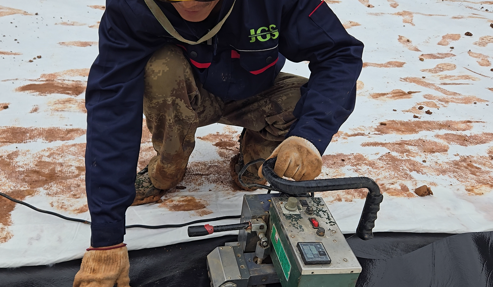
For High-Density Polyethylene (HDPE) and Linear Low-Density Polyethylene (LLDPE), Dual-Track Hot Wedge Welding is the industry standard process, which utilizes a metal wedge heated to 315°C to 425°C to melt the overlapping surfaces and completes the fusion by applying 300N to 400N of pressure through nip rollers.
This process forms two independent welds with an unwelded air channel in between, specifically for subsequent non-destructive air pressure testing according to the GRI-GM19 standard.
For T-joints, pipe penetrations, and repair areas, extrusion welding is required, which necessitates pre-grinding to remove the oxidation layer and controlling the extrudate temperature between 220°C and 260°C.
In contrast, PVC and EPDM materials mostly rely on chemical solvent bonding or butyl tape connection, and their seam shear strength is usually less than 80% of the base material, while the target strength of heat fusion welding needs to reach more than 95% of the base material’s yield strength.
QA/QC Testing
Non-Destructive Testing – NDT
- Air Pressure Testing
This is the standard testing procedure for dual-track hot wedge welds. An air channel 10mm to 15mm wide is left between the two parallel welds produced by the welder.- Pre-test Preparation: Technicians need to use a heat gun or special clamps to seal both ends of the segment to be tested (usually 50 to 150 meters), forming a closed cavity.
- Pressurization Process: Insert a hollow needle with a pressure gauge into the air channel and inject compressed air. For 1.5mm HDPE, the standard pressure is 30 psi (about 207 kPa).
- Pressure Retention Verification: After cutting off the air source, observe the pressure gauge for 5 minutes. According to GRI-GM19, if the pressure drop exceeds 4 psi (28 kPa), it is judged as a failure. This pressure drop tolerance considers natural pressure decay due to air cooling or pipe wall relaxation during the test.
- Fault Location: If the test fails, the air channel needs to be cut in sections to narrow down the search range until the leak point is found.
- Release Verification: After the test, the air channel must be cut open at the other end of the test segment. If a clear air release sound is heard, it proves the entire air channel is unobstructed and the test is valid; if there is no sound, it indicates a blockage in the middle of the air channel, and re-testing is required.
- Vacuum Box Testing
Specifically used for testing extrusion welds, repair patches, and T-joint areas.- Equipment Composition: A rigid box with a transparent polycarbonate observation window, equipped with a closed-cell neoprene gasket at the bottom, connected to a vacuum pump or venturi exhaust device.
- Operation Flow: Apply a foaming agent (soap solution) to the weld surface, place the vacuum box, and apply a negative pressure of about 5 psi (35 kPa).
- Observation Standard: Maintain negative pressure for 10 to 15 seconds, and technicians look through the observation window for continuously generated bubbles or air bubbles. Any bubble generation indicates a through-hole pinhole.
- Coverage: Each time the box is moved, it must overlap with the previous test area by at least 75mm to prevent missed inspections. Since this method is labor-intensive and slow (about 2 m/min), it is usually only used in areas where air pressure testing is not possible.
Destructive Testing – DT
- Sampling Frequency and Size
- Frequency: Industry standards usually stipulate taking one sample every 150 meters (500 feet) of weld. For high-risk projects (such as nuclear waste disposal), the frequency may increase to one every 100 meters.
- Sample Specification: Cut a 12-inch x 42-inch (about 30cm x 100cm) sample block on-site. The sample block is divided into three parts: one for on-site testing, one sent to a third-party laboratory, and one archived by the owner.
- Test Strip Preparation: The laboratory will cut the sample block into 10 test strips that are 1 inch (25mm) wide, 5 of which are used for shear testing and 5 for peel testing.
- Shear Testing (ASTM D6392)
Simulates the tension the geomembrane is subjected to on a landfill slope.- Loading Method: The tensile machine grips the membrane on both sides of the weld and applies a tension parallel to the membrane surface.
- Acceptance Criteria: For HDPE, the shear strength must reach 95% of the base material’s yield strength. For example, the yield strength of 1.5mm HDPE is about 22 kN/m, so the weld shear strength must exceed 20.9 kN/m. The break must occur in the base material, not at the weld interface.
- Peel Testing (ASTM D6392)
Simulates the tearing force the joint is subjected to and is the most rigorous method to check if the weld is a “cold weld.”- Loading Method: Peel the two layers of membrane in a T-shape, with the force perpendicular to the weld interface.
- Acceptance Criteria: The peel strength requirement for HDPE is lower, usually 62% of the base material’s yield strength.
- Elongation at Break: In addition to the strength value, the new GRI-GM19 specification also focuses on elongation (Separation) during the peeling process, requiring that the two layers of membrane must have significant tensile deformation before separation, indicating that molecular chains have been sufficiently entangled.
Failure Mode Codes
| Code | Full Name | Description | Judgment Result |
|---|---|---|---|
| FTB | Film Tear Bond | Film tear bond. The break occurs in the base material at the edge of the weld, and the weld itself remains intact. | Pass |
| AD | Adhesion Failure | Adhesion failure. The two layers of membrane completely separate at the weld interface, like a sticker being peeled off. Indicates welding temperature was too low or there were contaminants. | Fail |
| AD-Wld | Adhesion in Weld | Delamination within the weld. The break occurs inside the weld, usually caused by inclusions in extrusion welding or cold welding. | Fail |
| SE | Squeeze-out Break | Squeeze-out break. Only the squeeze-out melt at the edge breaks, which usually does not affect the main strength, but requires further evaluation. | Review |
Electrical Leak Location – ELL
- Arc Testing Method (ASTM D7240):
Applicable to exposed geomembranes.- Principle: If a conductive-backed geomembrane is used, technicians sweep a copper brush connected to a high-voltage source (15kV – 30kV) across the membrane surface.
- Phenomenon: When the copper brush passes over a pinhole, the current will break through the air and form a circuit with the conductive layer on the back, generating a visible arc and an accompanying audible alarm. This method can detect tiny holes below 1mm.
- Dipole Method (ASTM D7007):
Applicable to geomembranes covered with soil or water.- Principle: Electrodes are placed in the soil above the cover layer and below the membrane respectively, applying high-voltage DC electricity.
- Detection: If the membrane is intact, the current cannot pass through; if there is damage, the current will converge at the damage point. Technicians walk on the surface of the cover layer holding a detector to measure the potential gradient. When approaching a leak point, the voltage signal will fluctuate violently in a sine wave pattern. This technique can locate a 3mm damage point under 600mm thick soil.
The construction quality assurance (CQA) system for geomembrane installation strictly follows ASTM D6392 and GRI-GM19 standards, with non-destructive testing covering 100% of field seams:
Dual-track hot wedge welds must undergo air pressure testing, usually injecting 200 to 240 kPa of air pressure and holding for 5 minutes, allowing an absolute pressure drop of no more than 28 kPa;
Extrusion welds utilize vacuum box testing, maintaining a negative pressure of -35 kPa for at least 10 seconds on a surface coated with soap solution to capture tiny bubbles.
Destructive testing is sampled every 150 meters of weld, and the laboratory performs shear and peel tests on the samples.
The peel strength of HDPE welds must reach more than 62% of the base material’s yield strength, and the failure mode must present a Film Tear Bond (FTB), strictly prohibiting adhesion failure (AD).
In addition, the ASTM D7240 arc testing method can locate pinholes with a diameter of 1mm, suitable for complex areas where visual inspection is difficult.