HDPE geomembrane is commonly used for mine heap leach pads, and its main function is to prevent hazardous liquid leakage. It can withstand strong acids (such as sulfuric acid with pH 1–3) and is almost impermeable to water (permeability approximately 10⁻¹³ cm/s). Generally, the thickness is 1.5–2.0 mm; it is relatively strong and not easily punctured by stones. Seams are joined using hot-melt welding, with strength reaching more than 90% of the raw material, and air pressure testing is performed to ensure no leakage.
Chemical Resistance
Superior Molecular Structure
The process of manufacturing impermeable membranes is like building with giant LEGOs. Ethylene gas is squeezed in a pressure environment of 2 to 10 MPa, connecting into long lines composed of hundreds of thousands of carbon atoms. The weight of a single molecule is strictly controlled between 200,000 and 500,000 g/mol. Extra branch-like ramifications rarely appear on the lines, and the macromolecules are packed extremely tightly in space.
When the temperature drops below 130°C, the originally free-moving chains automatically line up in neat rows. Chain segments fold to piece together tiny lamellae with a thickness of only 10 to 20 nanometers. The lamellae are stacked layer by layer, and 40% to 60% of the area inside the material becomes an extremely strong crystalline body. At room temperature, the physical density of the material is fixed in the range of 0.940 to 0.960 g/cm³.
The physical distance between carbon atoms is forcibly compressed to 4.1 to 4.2 angstroms. In an environment of 25°C, the gaps left inside the material for external substances to exploit are less than 1%. Highly toxic sodium cyanide liquid at concentrations of 100 to 500 ppm turns into ions with a diameter of 3.6 angstroms. Facing extremely small microscopic gaps, the hydrated ions completely fail to find physical channels for inward penetration.
- The liquid permeability coefficient is as low as the tiny magnitude of 10⁻¹² cm²/s
- The barrier with a thickness of 1.5mm to 2.5mm blocks solvents completely outside
- The contact angle of liquid on the material surface is greater than 90 degrees, making it unable to spread
- Extremely high surface tension forces corrosive liquids to shrink into isolated water-bead shapes
Strong acid liquids with concentrations of 10 to 50 g/L are sprayed year-round in copper ore heaps. A large number of destructive hydrogen ions wander in the acid liquid with a pH value lower than 1.5. The composition of the impermeable membrane consists purely of carbon and hydrogen, forming a smooth wall without any electrodes. Free ions in the acid liquid cannot find weak breakthroughs on the wall to induce chemical reactions.
Carbon and carbon pull each other tightly using energy as high as 347 kJ/mol. Tearing the chemical link between carbon and hydrogen requires consuming 414 kJ/mol of energy. 1% to 2% of 1-hexene components are precisely mixed into the formula. Short side chains, like tiny ropes, tightly bind the crystalline regions and the soft regions without crystals together.
- The bottom bears the huge physical pressure of 50 to 100 meters high ore year-round
- The surface temperature remains in a warm state of 30°C to 60°C year-round
- Rope-like chains absorb the pulling deformation brought by uneven foundations
- Internal amorphous regions provide fine buffer space for molecules
Chemical liquid soaking at 50°C accompanied by external force pulling causes the tip of a scratch to pull out microscopic fibers several nanometers thick. The fibers hold tight at both ends of the crack, dispersing the tensile destructive force to the surrounding amorphous regions. According to the ASTM D5397 specification, the specimen is immersed in a 50°C solution containing 10% Igepal and a constant load is applied. The specimen withstood more than 500 hours without physical fracture.
Special black carbon powder of 2.0% to 3.0% was kneaded into the raw material during extrusion processing. Powder particles with a size of 20 to 30 nanometers are responsible for absorbing destructive light with wavelengths of 290 to 400 nanometers. High-energy photons are completely intercepted after penetrating 50 microns of the surface. Deep light-sensitive macromolecular long chains avoid the fate of photodegradation fracture and safely survive for 20 to 30 years.
- Machine test values for oxidative induction time are all above 100 minutes
- HP-OIT test results in high-pressure environments exceed 400 minutes
- The molecular weight of antioxidant substances is deliberately maintained above 500 g/mol
- The highly crystalline state suppresses the loss rate of chemical additives to one part per million
Ensuring Zero Loss of “Pregnant Leach Solution” (PLS)
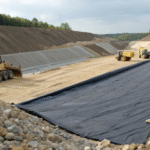
Water flow carrying metal components drips downward along gravity, passing through 50 to 100 meters thick crushed stone blocks. Piles of ore like mountains squeeze out a physical weight exceeding 300 kilopascals at the bottom. Workers lay 2.0 mm thick impermeable plastic paper on compacted mud ground. Water generated from washing gold mines contains 3 to 5 ppm of gold components.
The concentration in silver mine puddles is maintained at 20 to 30 ppm. Giant water pumps suck the water into the refinery workshop with an ultra-large flow rate of 10,000 liters per minute. The water flow runs day and night along ditches with a slope of 2% to 5%. A flow velocity of 0.5 meters per second flushes tons of precious metals into the catchment pool.
The path of the water and metal mixture is blocked by this layer of smooth macromolecular plastic paper. The physical water seepage value of this membrane stays at an extremely small 10 to the power of minus 12 centimeters per second.
- The water naturally leaking from 1 hectare of area per year cannot fill a drinking cup
- The allowable water leakage value for a single hole is limited to below 5 liters per hectare per day
- A 10-meter deep water tank filled with water and left for 72 hours shows no trace of water vapor
- A water bead contact angle greater than 90 degrees makes it impossible for liquid to squeeze into the gaps of the membrane
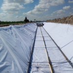
Tens of thousands of sheets of impermeable paper overlap their edges at the construction site. Construction masters push hot wedge welding machines to melt the edges under a heat of 400°C to 450°C. The machine keeps crawling forward at a constant speed of 2 to 3 meters per minute. Two pieces of softened plastic are firmly pressed into a whole large net by 200 to 300 Newton iron wheels.
A hollow air channel 10 mm wide is left in the middle of the pressed double-seam line. Inspectors take a needle and pierce it into the gap, filling it with 250 to 300 kilopascals of compressed air. After quietly waiting for 5 minutes, the air pressure number on the dial has not dropped past the 10% scale line.
Take the cut-off scraps to perform the ASTM D6392 destructive pulling test. The laboratory machine clamps both ends and tears hard to both sides at a speed of 50 mm per minute.
- The physical peel tension reading at the seam position stays steadily above 15 kN/m
- The position where the material is completely torn off always appears in areas outside the seam
- Solid resin plastic strips with a diameter of 4 or 5 mm are stuffed into the hand-held extrusion gun
- Melted hot solder exposed to the air takes only 15 to 20 seconds to blow cool and shape
Relying on human eyes to search a huge flat ground of 500,000 square meters takes several months. Operators push a dual-pole spark tester to release 200 to 400 volts of DC current on the surface of the plastic membrane. The charge follows tiny holes on the membrane down to find the underlying mud. The machine emits a sharp buzzing sound, catching hidden small holes only 1 mm wide.
One person walking for a day can sweep an 10,000 square meter area of stones. Broken edges with holes are completely cut off with a knife, and a disc-shaped adhesive patch with a much larger area is covered on top. Use an engineering ruler to measure the width of the patch and the base membrane overlapped together; the scale is all above 150 mm.
Environmental Protection Line
Environmental protection departments keep a close eye on mines that consume tens of thousands of tons of chemical medicines every day. Cyanide used for extracting gold escapes into nature; as long as a concentration of 0.2 ppm is mixed into the water, fish in the river will float up with white bellies on a large scale. High-density polyethylene plastic paper is laid flat on the mud, completely separating poison from the groundwater network. Inspectors must look through discharge data reports as thick as 500 pages every month.
The mine owner dug rows of groundwater monitoring wells at a depth of 50 meters under the waste rock pile. Water pumps punctually pump up 20 liters of water samples every day to be sent to the laboratory for spectroscopy. The reading of heavy metals in the water is strictly stuck under the passing line of 0.01 mg/L. Even if only one drop of toxic acid water penetrates into the mud, the fine amount issued by the court will ruthlessly skip seven figures.
Drinking water sources for local people are scattered within a range of 3 kilometers outside the mining area. The groundwater layer is hidden in the gaps of sand and stone, moving slowly toward the surrounding villages at a speed of 5 meters per day.
In the dark mud deep underground, the plastic membrane bears thousands of tons of weight pressed down by the ore above. The mud carries various tiny bacteria that love to eat acid, gnawing at surrounding objects day and night. Macromolecular hydrocarbon chains make the bugs lose their appetite completely, and digestive enzymes spat out by bacteria have no way to deal with the non-polar plastic surface. Test pieces buried in the soil for a full 20 years were dug out, and under the microscope, no gap bitten by bugs could be found.
- The 2.0 mm thick plastic layer keeps all toxic water in the specified circle
- Laying 1 hectare of land requires consuming 19,000 kg of membrane material
- Magnifying 500 times to look at the membrane surface, no trace of microorganisms making a home can be found
- Plastic sheets buried in strong acid soil for 36 months did not lose points in the hardness test
- The puncture resistance strength against rough sand and stone extrusion exceeded 400 Newtons
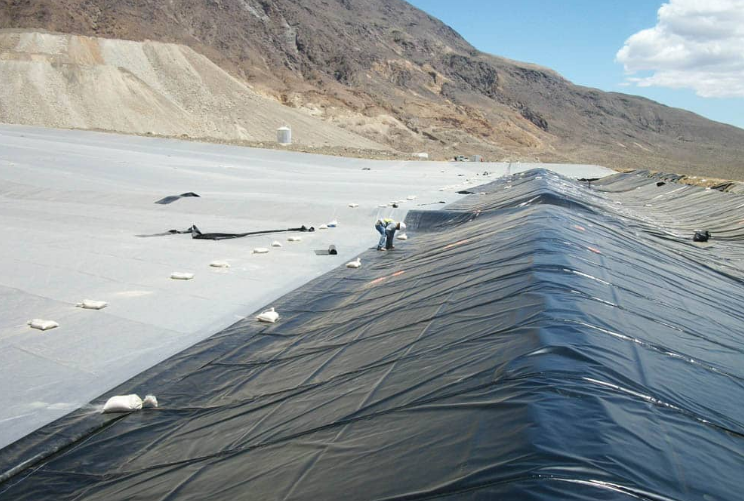
Large mines are now all standardly equipped with double-layer impermeable structures. A grid-shaped plastic mat with a thickness of 5 mm is sandwiched between two layers of polyethylene membrane. The top membrane is punctured by a sharp stone with a small 2 mm hole, and the toxic water leaking down flows along the grid in the middle. The water flow is all led into that perforated corrugated pipe with a diameter of 200 mm buried at the edge.
The leaked acid water runs for 500 meters in the pipe and falls into the collection vertical shaft at the lowest terrain. The sensor probe keeps its eyes open 24 hours a day staring at the water accumulation tank between the double-layer membranes. The water level rises, crossing the 5 mm scale line, and the alarm signal runs along the optical cable into the large screen of the monitoring room 10 kilometers away.
The red light on the computer screen flashes frantically at a frequency of 3 times per second. The alarm sound shouted from the speaker soared the decibels above 85, urging the person on duty to quickly turn off the spray valve above.
Workers hold GPS locators in their hands to search for leakage breakthroughs on the flat ground covering 200,000 square meters. The layer of membrane padded at the very bottom lies intact on the mud, firmly blocking dangerous chemical medicines. Bugs and plant roots in the mud cannot smell a trace of acid water. Two insurances suppress the probability of poisons running into groundwater at an extremely low level of one in a million.
After the mining pit finished mining and stopped work, the whole site ushered in a large-scale grass-planting and landfill project. Bulldozers smooth 1.5-meter thick clean loess at the highest point of the waste rock pile. The impermeable membrane is like a large fresh-keeping bag, sealing 50 million tons of stones soaked in chemical medicines inside without gaps. Rainwater pours on the mud and grows weeds; roots grow downward and are forcibly blocked by the impermeable membrane at the top.
The roots of the weeds can only find water to drink along the smooth plastic paper to the side. Toxic residues are forever locked in the dark underground room without sunlight.
- 100,000 fir saplings were planted on the hilltop of the closed mining pit
- The loess covered on the top was rolled by a road roller to a 95% firmness
- Chemical residual water in the waste rock pile was pumped dry to only 5% moisture left
- The top layer membrane is spread along a 3% slope used to drain away mountain rainwater
- 10 cubic meters of concrete are poured into the edge deep ditch to firmly bite the membrane
Puncture Prevention
Base Foundation Control
Bulldozers level the surface, clearing away the top 300 mm thick weeds and sludge. Workers carry GPS equipment to measure, keeping the height difference within plus or minus 15 mm. Soil brought in must pass through a sieve once, with the mesh size firmly locked at 12 mm. Stones and branches exceeding 12.5 mm are all picked out and thrown away.
Clean fine soil is spread on the ground. Engineers hold rulers to measure; one layer of soil can only be spread 200 mm thick, and if more is spread, it must be shoveled away and restarted. A 14-ton road roller comes over and rolls back and forth on the soil 8 to 10 times. Air in the soil is squeezed out, becoming rock hard.
A sprinkler truck sprays some water mist, and an engineer digs up a handful of soil to test the moisture content. The screen jumps to 11.5%, which is just within the specified moisture range. After the road roller leaves, an instrument is inserted into the ground to measure density; the reading is 1.95 g/cm³. The standard Proctor index stays at 96.2%.
A batch of rigid tests was performed on the soil layer:
- Liquid limit index is less than 30
- Plasticity index is less than 15
- Bearing capacity value exceeds 15
- Permeability coefficient is 1×10^-5 cm/s
The inspector places a 3-meter long aluminum ruler flat on the ground. The maximum gap between the ruler and the ground is only 8 mm. The slope of the entire site is only 0.5%, just enough to let rainwater flow away slowly. Heavy trucks fully loaded with water tanks drive across from above, and the tires only leave marks less than 10 mm deep.
Drainage pipes with a diameter of 100 mm are hidden underground. The pipes are buried in a 1.2-meter deep ditch, wrapped in a layer of non-woven fabric. The surroundings of the pipe network are filled with crushed stone 10 to 20 mm wide.
Data for the groundwater network has strict regulations:
- Blind ditch slope is maintained at 1%
- Groundwater level is stuck 2 meters deep under the membrane
- The pipe drains away 50 liters of water per second
- The water measurement well is 5 meters deep
Non-woven Geotextile Buffer Layer
Rolls of white geotextile are unloaded by forklifts next to the impermeable membrane; these rolls have a fixed width of 6 meters and a length usually of 50 or 100 meters. This material feels like thick wool felt and is made of polypropylene (PP) short fibers through a needle-punching process.
Thousands of crochet needles on the machine punch continuously at a speed of 600 times per minute, locking messy fibers together. The fineness of each fiber is only 2 to 6 dtex. The thickness of the finished geotextile is controlled between 4.0 mm and 8.0 mm.
The bottom of the heap leach pad bears the pressure of the 100-meter high ore pile above; the weight per square meter of the buffer layer cannot be lower than 600g. In higher pressure areas, specifications will increase to 800g or even 1200g to ensure that sharp corners of ore cannot puncture this layer of barrier.
| Physical Index Parameters | 600g/m² Spec | 800g/m² Spec | Test Standard |
|---|---|---|---|
| CBR Puncture Strength | 4800 N | 6500 N | ASTM D6241 |
| Grab Tensile Strength | 1600 N | 2200 N | ASTM D4632 |
| Trapezoidal Tear Strength | 600 N | 850 N | ASTM D4533 |
| Apparent Opening Size (O95) | 0.07-0.2mm | 0.05-0.15mm | ASTM D4751 |
When a 50 mm sharp ore presses on the fabric surface, the internal three-dimensional fiber structure will undergo displacement. Several tons of pressure originally concentrated on one point are quickly shared across an area of 150 to 200 square millimeters.
In the laboratory, a steel column with a diameter of 50 mm presses down at a speed of 50 mm per minute. Fabric with 600g specification must hold up to 4800 Newtons of force before being pushed open. This data ensures that when bulldozers drive over it, the membrane remains intact.
Testers put samples into a UV aging box and continuously shine strong light for 500 hours. When taken out and stretched again, the strength must still be more than 70% of the original. Light stabilizers are mixed into the fibers to prevent these white fabrics from becoming brittle and yellow after being exposed to the sun for a few days on the construction site.
Requirements for overlap dimensions in laying operations are very rigid:
- Overlap 300 mm between two widths of fabric
- Where the slope is greater than 1:3, overlap 500 mm
- Hot air gun spot welding, with weld spots placed every 1 meter
- Strictly prohibited to use small scraps of cloth to patch everywhere
Construction personnel walk on the site wearing flat-bottomed soft shoes. Where holes are found, a patch of the same material must be cut and covered. The edge of the patch should be 200 mm larger than the damaged area, then use a portable sewing machine to sew two lines around it, with stitches controlled at 6 to 10 mm.
This kind of fabric has 80% of voids inside that are empty. The moving speed of water flow inside can reach 0.3 centimeters per second. If there is accumulated water on the membrane, this water will quickly flow to the drainage pipe along the voids in the cloth and will not swirl in the foundation.
Under a heavy pressure of 500 kilopascals, the geotextile will be squeezed flat by 60% of its thickness. Even if only 2.5 mm thick is left, the fiber toughness inside it can firmly resist those 5 mm crushed stones in the foundation, not letting stones touch the black membrane below.
- Grab Elongation: 50%
- Vertical Permeability Flow: 0.5 liters/second/square meter
- Chemical Resistance: No degradation between pH 2 and 13
- Coefficient of Friction: Greater than 0.25
Technicians randomly cut a 100 square centimeter sample and weigh it on a scale. Once the gram weight error exceeds 5%, it indicates this roll of cloth is too sparse to resist the squeezing force at the bottom of the ore. This batch of goods will be cleared from the site immediately and not allowed to enter the laying area.
Breaking work data measured by the laboratory is usually above 30 Joules. The higher this value, the more impact energy the material can absorb before being crushed.
HDPE Indicators
Heavy trailers stop at the mining area unloading yard, and black membranes wound on steel cores are lined up in order. Each roll of this batch is 140 meters long and 7 meters wide when unfolded. Workers hold vernier calipers and randomly select points at the edge of the membrane; the reading on the electronic screen jumps at 2.03 mm.
The thickness error of the whole roll of membrane is limited within plus or minus 10%. Quality inspectors cut a coin-sized disc every 1.5 meters and send it into the thickness gauge. If the average of ten measurements falls below 1.8 mm, the entire batch of material will be labeled as unqualified and sent back to the warehouse.
Raw material tanks producing these membranes contain 97.5% polyethylene resin and 2.5% carbon black. These carbon black particles are extremely small, with a diameter of only 10 to 20 nanometers. The laboratory measured the density of this mixture as 0.940 g/cm³, ensuring that molecules are packed very tightly.
The tensile machine works in a constant-temperature room. Technicians clamp dumbbell-shaped samples onto the machine claws. The motor turns, pulling upward at a constant speed of 50 mm per minute. The red curve on the screen rises sharply as the tension increases.
When the sample is stretched by 12%, the machine makes a beep. At this time, the tension reached 29 kN/m, which is the critical point where the membrane body begins to deform. This ability ensures that when the membrane is pressing tens of thousands of tons of ore, it can rely on slight deformation to shed that brute force.
The claws continue to tear to both sides, and the sample is stretched into a thin line. It was not until the length was stretched to more than 7 times the original, i.e., 700% elongation, that the sample broke with a pop. The tensile strength shown at this time exceeded 53 kN/m.
The assessment standards of the laboratory for incoming raw materials are very rigid:
- Flow rate after melting is less than 1g per 10 minutes
- No oxidation for 400 minutes in high-pressure oxygen
- Carbon black must be uniformly dispersed, with a rating reaching Grade 1
- Pure resin particles cannot be mixed with any recycled old material
An 8 mm thick flat-head steel needle is used for the puncture resistance test. The steel needle presses against the fixed membrane surface like slow motion. As pressure increases, the membrane surface sinks deeply like a tightened drum skin until the reading jumps to 700 Newtons.
The force of 700 Newtons is equivalent to a 140-pound adult standing on a place as small as a fingernail. Molecular chains inside the membrane body hold tight like a fishing net, dispersing the sharp corner pressure that would have punctured the membrane to a larger area around it.
Right-angle tear tests are conducted nearby at the same time. Workers cut a 90-degree notch on the sample, and the machine exerts force in the opposite direction. Tearing this kind of membrane with a wound requires 187 Newtons of force, which ensures that small scratches occasionally occurring during construction will not become large cracks.
For those highly corrosive liquids in the mining area, membrane samples are soaked in medicine pools:
- Water temperature constant at 50 degrees Celsius
- Special activators added to the medicine
- Hang a weight of 30% of the original strength on the sample
- Soaking continuously for 500 hours like this without cracking
Engineers put membrane samples into an oven at 85 degrees Celsius and bake them for 90 days. After taking them out and testing again, more than 55% of the antioxidant components inside must remain. Carbon black blocks ultraviolet rays here, so the membrane will not become as brittle as a biscuit under the scorching sun.
The freezer at minus 70 degrees Celsius was opened, and the samples were frozen hard. A heavy hammer fell from a high place, hitting these membranes that were like ice blocks. After hitting 10 samples continuously, no crack could be seen on the surface, which ensures that the membrane will not crack during construction in extremely cold weather.
In summer, the construction site ground can reach 70 degrees Celsius. 2.0 mm thick black membrane will have obvious thermal expansion and contraction; for every 100 meters in length, it will elongate by 1.2 meters. Workers have to weld before dawn when the temperature is low, at which time the size of the membrane is most stable.
The dual-track welding machine crawls over the overlap of the membrane. The heating block in the machine is heated to 500 degrees Celsius and moves forward at a speed of 2 meters per minute. A cavity will be left between the two seams after welding, specially used to pump air for pressure testing to see if there is any air leakage.
There are several measured indicators for the firmness of the weld:
- Two people peel the weld with force; the tension must exceed 130 Newtons
- When tearing, it must be the membrane body that breaks, and the weld cannot de-bond
- Shear tension should reach 95% of the strength of the membrane itself
- A segment must be cut for every 150 meters welded and sent to the laboratory for destructive stretching
In those slope positions, in order to prevent ore from sliding down, membranes with a rough surface will be used. The factory sprays resin on the membrane surface during production to create sandpaper-like protrusions. An altimeter measures that the height of these small protrusions is all above 0.25 mm.
Originally smooth membrane placed on a slope, things on it cannot sit still once tilted to 11 degrees. After switching to this textured membrane, the friction angle directly increased to 26 degrees. Even if dozens of meters of heavy stones are piled on the slope, they will firmly grasp the membrane surface without slipping.
Seam Integrity
Welding Process
A copper heating wedge is installed in the center of the dual-track welder, with length controlled at 60mm to 90mm. Driven by a 1500W heating element, the thermocouple probe is only 3mm away from the wedge surface, ensuring the real-time displayed 380°C error does not exceed 2°C. This precision can control the motion state of polyethylene molecular chains under high temperature, preventing thermal degradation.
The drive wheel set adopts an independent suspension system, applying 450N to 500N vertical pressure to the 1.5mm thickness HDPE membrane. The wheel surface is engraved with 0.5mm deep anti-slip patterns, maintaining a constant speed of 2.0m/min even on a 20-degree slope. The compression amount of the pressure spring needs to be precisely adjusted; thinning the edge of the weld bead will cause strength damage.
| Membrane Thickness (mm) | Working Temperature (°C) | Welding Speed (m/min) | Welder Pressure Setting (N) |
|---|---|---|---|
| 1.0 | 360 – 380 | 2.5 – 3.0 | 350 – 400 |
| 1.5 | 385 – 405 | 2.0 – 2.5 | 450 – 500 |
| 2.0 | 410 – 425 | 1.5 – 1.8 | 500 – 550 |
| 2.5 | 420 – 435 | 1.1 – 1.4 | 550 – 600 |
The surface cleanliness of the heating wedge directly affects heat transfer efficiency. During operation, a fine copper brush must be used every hour to remove carbides on the surface. If the carbide layer thickness reaches 0.1mm, the heat transfer coefficient will drop by more than 15%, resulting in cold welds in the bead. The 10mm wide air cavity left between the dual tracks must be clearly formed, which is the basic space for subsequent air pressure detection.
The handheld extruder weighs 5.5kg and is dedicated to the sealing of patches and pipe penetrations. An internal screw feeder forcibly pushes 4mm diameter HDPE welding rods into the melting chamber, which are sprayed out after being heated to 245°C. The front end is equipped with a 260°C hot air nozzle, completing the preheating and softening of the base material surface 0.5 seconds before laying the molten glue, achieving cross-linking fusion between interfaces.
Grinding procedures before extrusion welding have strict requirements. The grinding head rotation speed needs to be controlled below 5000rpm, and the grinding depth is limited within 8% of the membrane thickness. Teflon welding shoes are replaced according to 1.5mm or 2.0mm membrane thickness, ensuring the formed weld edge slope is between 60 degrees and 90 degrees, and the molten material output is stable at about 2.1kg per minute.
- The Melt Flow Index (MFI) of the welding rod must be in the range of 0.2 to 0.5g/10min.
- The error between the extrusion thermostat display value and the actual molten glue outlet temperature is strictly prohibited to exceed 5°C.
- The preheating airflow rate needs to be stable at 300 liters per minute.
- The welder nozzle and the membrane surface need to maintain a 45-degree angle and move at a constant speed.
The geotextile buffer layer laid under the impermeable membrane has a gram weight selected at 600g/m². The CBR puncture strength determined value of this filament material needs to be greater than 2500N, relying on its three-dimensional fiber structure to neutralize concentrated loads generated by 20mm crushed stones in the bottom layer. When laying, adjacent fabric widths overlap by 150mm, and industrial sewing is performed using high-strength polypropylene thread.
For high leakage risk areas, Geosynthetic Clay Liners (GCL) are often used as a secondary barrier. No less than 4.8kg of sodium bentonite is wrapped in each square meter of liner, and the swelling ratio when meeting water needs to exceed 24 times. The permeability coefficient of the sealing layer it forms is as low as 10^-11 m/s, which can automatically repair local puncture points with a diameter less than 5mm.
Special bentonite sealing powder needs to be scattered at the edge seams of the GCL, with a dosage of 0.4kg per linear meter. After laying is completed, it must be covered by the upper HDPE membrane within 24 hours to prevent natural rainfall from causing premature hydration swelling of the bentonite. The composite coefficient of this multi-layer structure can improve the overall impermeable performance by two orders of magnitude.
A 300mm thick sand cushion is standard for large heap leach pads, with mud content required to be below 5%. Compaction is detected using a nuclear density gauge, and needs to reach a dry density index of over 92%. The sand grain size distribution needs to be uniform, and hard stones with a diameter exceeding 12mm are strictly prohibited to prevent inducing point stress on the impermeable membrane under the pressure of a 60-meter ore pile.
- The flatness error of the sand cushion surface does not exceed 10mm every 3 meters.
- The Grab Strength requirement for geotextile is greater than 1100N.
- The drainage layer Gradient Ratio test needs to be less than 3.0.
- The trapezoidal tear strength of the material is maintained above 450N.
The exhaust system buried in the buffer layer uses perforated pipes with a diameter of 50mm. The pipe spacing is set at 20 meters, wrapped with geotextile filter membrane to prevent dust blockage. If the value monitored by the air pressure sensor exceeds 5kPa, a forced exhaust program needs to be started to avoid gas accumulation at the bottom pushing up the impermeable membrane and destroying the physical stability of the weld.
The medical-grade stainless steel needle equipped on the air pressure tester is pierced into the 10mm air channel of the dual-track weld. Air is pumped to 30 psi (210 kPa) and then sealed; observe the pressure gauge reading within 5 minutes. If the pressure drop exceeds 3 psi, micron-level leak points need to be searched along the weld. For complex joints, a 25kV high-voltage spark detector is used.
Before daily operation, a 1.2-meter long trial weld strip is cut on site. Use a portable tensiometer to test its peel strength; the standard line for 1.5mm membrane material is 78 lb/in. For every 150 meters of formal weld completed, a set of samples must be cut and sent to the laboratory for destructive experiments under the ASTM D6392 standard.
Detection Standards
The 10mm central air channel left by the dual-track weld is a natural channel for verifying airtightness. The tester pierces an inflation needle with a pressure gauge into one end of the air channel, uses a hot-melt extrusion gun to seal the other end, and pumps in compressed air to bring the internal pressure to 30 psi (210 kPa).
The stability of the pressure gauge reading directly quantifies the continuity of the weld. Within the 5-minute observation period, the pressure drop is strictly prohibited to exceed 3 psi (21 kPa). If the pointer shows a significant decline, high-concentration soapy water must be applied to the weld surface to locate micron-level leak points by the position of bubbles popping out.
For extrusion welds of patches or odd-shaped pieces that cannot form air channels, a vacuum box must be used for detection. A transparent plexiglass cover is placed on the weld coated with lubricant, and a vacuum pump draws the internal air pressure to about -35 kPa (-5 psi).
In a negative pressure environment lasting 15 seconds, if the soapy water produces continuous breaking bubbles, it proves that a penetrating hole exists at that point. This detection method requires every overlapping area to maintain at least 10% visual overlap range to ensure the vacuum pump can completely cover the section under inspection.
At corners with complex structures such as pipe boots and sump pits, a 25kV high-voltage spark detector is the final means of data control. A thin copper wire is pre-buried under the weld during construction, and the detection probe sweeps over the weld bead; if there is a physical gap inside, the high-voltage arc will instantly break through the air and generate sparks.
| Detection Item | Technical Parameter Index | Judgement Standard | Detection Coverage |
|---|---|---|---|
| Air Pressure Test | 30 psi / 5 min | Pressure Drop < 3 psi | 100% (Dual-track Weld) |
| Vacuum Test | -35 kPa / 15 sec | No bubbles generated | 100% (Extrusion Weld) |
| Spark Test | 15kV – 35kV | No breakdown sparks | 100% (Complex parts) |
| Destructive Sampling | One per 150 meters | Accord with ASTM D6392 | Sampling (Specified by CQA) |
After completing the site scan, destructive testing must be performed according to the ASTM D6392 standard. A set of 300mm × 1100mm samples is cut for every 150 meters of weld bead and divided into 10 standard test strips with a width of 25.4mm (1 inch).
These test strips are fixed on a portable tensiometer and stretched to both ends at a constant speed of 50mm/min. For HDPE membrane with a thickness of 1.5mm (60 mil), the peel strength must reach 78 lb/in, while the shear strength needs to break through the threshold of 120 lb/in.
The peel test tests the molecular fusion depth of the welding surface, and the shear test verifies the ability of the weld to bear horizontal displacement. 5 strips undergo peel experiments, and the other 5 undergo shear experiments; as long as one strip fails to meet the standard, the entire 150-meter weld will be judged as rejected.
- Peel strength for 1.0mm thickness membrane material needs to be greater than 52 lb/in.
- Peel strength for 2.0mm thickness membrane material needs to be greater than 104 lb/in.
- The fracture position of the test strip must occur in the base material area rather than the welding surface.
- The peel percentage of the weld bonding area is strictly prohibited to exceed 10%.
The ideal experimental result is called Film Tear Bond (FTB). This indicates that the structural strength of the weld itself has exceeded the tensile limit of the base material, and the molecular chains have been completely reorganized under high-temperature extrusion. If the fracture surface peels off smoothly at the weld interface, it indicates that the welding temperature or pressure failed to reach the glass transition point of the material.
Laboratory technicians will record every set of data and compare it with the initial parameters of the trial weld of the day. The integrity of this data chain ensures that even if leakage occurs years later, it can be traced back to the wind speed, temperature, operator ID, and welder number of that day through the serial number.
For thickened membrane material above 2.0mm, the accuracy of the tensiometer’s load sensor needs to be maintained within ±1%. If the ambient temperature is lower than 10°C, test strips need to be stored in a constant-temperature box for no less than 40 minutes before entering machine testing to avoid cold brittleness effects interfering with the true strength reading.
- Sampling frequency is once every 150 meters, or at least twice per work shift.
- Sample numbers must correspond one-to-one with the weld coordinates on the anti-seepage plan.
- Laboratory reports must include load-displacement curve diagrams.
- All sampling holes need to be sealed using circular patches within 2 hours.
Site Variable Control
Entering the heap leach pad construction area in the early morning, the 1.5mm thick HDPE membrane surface appears in a tightened state. With direct sunlight, the membrane surface temperature climbs from 15°C to above 50°C within two hours. This material has an extremely high coefficient of thermal expansion, and a 100-meter long roll will produce approximately 60cm of physical elongation under this temperature difference.
If long-distance welding is forced at this time, the originally flat membrane surface will form undulating waves because of expansion. These waves are called “fish mouths” in professional terminology. If not cut open and re-overlapped in time, after the welder forces its way through, the internal stress generated by cooling contraction will cause the weld to undergo brittle cracking within weeks.
Operators must carry membrane thermometers at all times, measuring surface values every 30 minutes. When the temperature exceeds 45°C, the traveling speed of the hot wedge welder needs to be increased from 2.0m/min to above 2.5m/min. This is to shorten the contact time between the high-temperature wedge and the membrane material, preventing excessive melting that causes thickness thinning to exceed the industry red line of 10%.
Wind speed is another variable interfering with heat balance. When site gusts exceed 20km/h, the heat loss rate of the exposed hot wedge will suddenly increase. To maintain the stability of the molten pool, the operator needs to adjust the set temperature compensation higher by 20°C. If this dynamic intervention is not performed, small discontinuous crystallizations will be generated inside the weld bead, failing to pass subsequent pressure tests.
The impact of ambient humidity on welding quality often occurs at the molecular level. When relative humidity is higher than 80%, a microscopic dew hard to see with the naked eye will form at the edge of the film. This moisture vaporizes instantly when the hot wedge sweeps over, leaving micro-bubbles with a diameter less than 0.1mm inside the weld. These pores will evolve into leakage channels under 600kPa heap load pressure.
Construction teams are usually equipped with high-power industrial hot air blowers to perform preheating and dehumidification on the overlap area 10cm ahead of the welder. The cleaning range must extend to 75mm on both sides of the weld centerline.
- Wiping cloths adopt lint-free pure cotton material; a new cloth must be replaced every 150 meters of welding completed.
- The use of cleaners containing solvents is strictly prohibited; only 99% concentration isopropyl alcohol is allowed for wiping.
- If the cleaned membrane surface has not completed welding within 20 minutes, the cleaning procedure must be executed again.
- Observe the molten glue squeezed out at the edge of the weld; its width should be maintained between 1mm and 2mm.
- The rod rotation extruder needs to empty 50g of overheated degraded material remaining in the barrel before starting.
The stability of power supply is directly related to the degree of cross-linking of molecular chains. Heap leach pads are vast, and long-distance power lines will cause voltage drops. If the voltage falls from 220V to 200V, the actual fluctuation of hot wedge temperature will exceed ±5°C. This fluctuation is enough to let the welding interface degrade from molecular fusion to simple physical adhesion.
Each welder must be equipped with an independent regulated power supply, and the power margin of the generator set needs to be greater than 30% of the rated power. In the early morning, noon, and afternoon of each day, 300mm long trial blocks must be cut respectively for on-site tensile testing.
- Trial blocks must reach “Film Tear Bond (FTB)” state on the tensiometer.
- Peel strength for 1.5mm membrane material needs to be greater than 78 lb/in.
- Shear strength needs to stay stable above 120 lb/in.
- Effective bonding width of the weld bead shall not be lower than 15mm.
- The air cavity width between dual-track welds is fixed at 10mm.
For extrusion welding in irregular areas, the grinding process is the prerequisite for success. The handheld grinder rotation speed needs to be controlled below 5000rpm to prevent heat generation from friction causing thermal degradation on the membrane surface. The grinding depth is strictly limited to within 10% of the base material thickness, i.e., around 0.15mm.
The surface after grinding must present a uniform matte texture, and the grain direction should be perpendicular to the weld traveling direction. This unevenness at the microscopic level increases the mechanical interlocking force between the molten welding rod and the base membrane. The diameter of the welding rod for extrusion welding is usually 4mm, and its Melt Flow Index (MFI) must maintain a matching degree of ±0.1g/10min with the base membrane.
Slope operations put forward higher physical requirements for field control. In areas with a slope greater than 1:3, seams of the impermeable membrane must be parallel to the slope direction. Horizontal welds are strictly prohibited on the slope because shear force generated by ore settlement will directly act on the weld edge, leading to stress concentration tearing.
The designed depth of the anchor trench is usually 800mm, and the width is 500mm. After the membrane material enters the trench, at least 1000mm of surplus must be reserved, and layered backfilling is performed using fine soil with a compaction degree reaching 95%. This structure can resist overall sliding caused by rainstorm flushing, protecting the bottom welds from being pulled off.
The flatness of the heap leach pad base layer determines the long-term life of the weld. Crushed stone particle size must be less than 20mm, and there can be no sharp protrusions on the surface. Once a depression exceeding 30mm exists in the base, the impermeable membrane will undergo local stretching under a 50-meter ore heap load, and the strain rate at the weld will instantly exceed the yield limit of 20%.
Non-destructive testing is the last line of defense to verify integrity. The test pressure of the dual-track weld needs to be filled to 30 psi (210 kPa).
- Observe the swing of the pressure gauge pointer within 5 minutes.
- Pressure drop exceeding 3 psi is judged as the existence of hidden micropores in that segment of the weld.
- Use an ultrasonic thickness gauge to randomly sample the weld bead; deviation is strictly prohibited to exceed 10% of the designed thickness.
- During vacuum box testing, negative pressure needs to be maintained above -35 kPa.
- If the diameter of bubbles generated by soapy water exceeds 2mm, that segment must be cut off and repaired again.
Repair work also follows strict geometric specifications. All patches must be cut into circular or elliptical shapes, and the edge corner radius shall not be less than 75mm.