
Determine geomembrane thickness from the project specification, support conditions, installation damage, service loads and durability requirements—not from water depth or soil name alone. Convert mil and millimetres accurately, distinguish nominal thickness from acceptance limits, and assess the complete liner–protection–subgrade system.
Convert mil and millimetres without changing the specified grade
One mil is one thousandth of an inch: 1 mil = 0.0254 mm. Multiply mil by 0.0254 to obtain millimetres; divide millimetres by 0.0254 to obtain mil. A mil is not a millimetre, and an exact conversion is not a manufacturing tolerance.
| Specified dimension | Exact conversion | Common nearby metric designation |
|---|---|---|
| 20 mil | 0.508 mm | 0.5 mm |
| 30 mil | 0.762 mm | 0.75 mm |
| 40 mil | 1.016 mm | 1.0 mm |
| 60 mil | 1.524 mm | 1.5 mm |
| 80 mil | 2.032 mm | 2.0 mm |
| 100 mil | 2.540 mm | 2.5 mm |
The last column is not an authorization to substitute dimensions. State which unit system and acceptance table govern the order. For example, 1.5 mm is approximately 59.06 mil; if the design requires 60 mil, clarify acceptance before supplying a product labelled 1.5 mm.
Read thickness acceptance separately from the measurement method
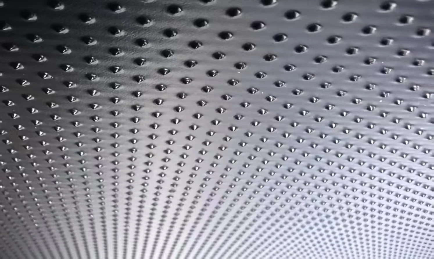
ASTM D5199 addresses nominal-thickness measurement for applicable geosynthetics and directs textured geomembranes to D5994/D5994M. Measurement pressure and contact geometry matter. A hand caliper reading is not automatically equivalent to the specified test, and asperity height is not core thickness.
Under GRI-GM13 Revision 19, June 11, 2025, the smooth-sheet table requires a minimum average at nominal thickness and limits the lowest of ten values to 10% below nominal. These are separate requirements. For a 1.5 mm nominal smooth sheet, an individual 1.35 mm reading does not prove the roll passes: the average and all other requirements must also comply. Textured-sheet and weld-edge criteria differ; use the relevant table rather than a blanket “±10%” rule.
Record the specified edition, specimen location, calibrated instrument, individual readings, average and roll identification. Quarantine a disputed delivery and resolve it through the project’s acceptance procedure; a failed reading does not itself define a universal disposal or retesting instruction.
Evaluate soil support and protection before adding thickness
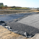
Clay, sand and rock descriptions are too broad to select a liner grade. Inspect sharp protrusions, loose material, soft spots, voids, roots and differential-settlement potential. Smooth sand can still move or wash out; a thicker liner cannot repair an unstable foundation.
Define subgrade preparation, compaction test basis, acceptable moisture range and inspection hold points in the approved specification. “95% compaction” is incomplete without the reference laboratory method and required field testing. Laboratory break elongation is not an allowable field strain or permission to bridge a cavity.
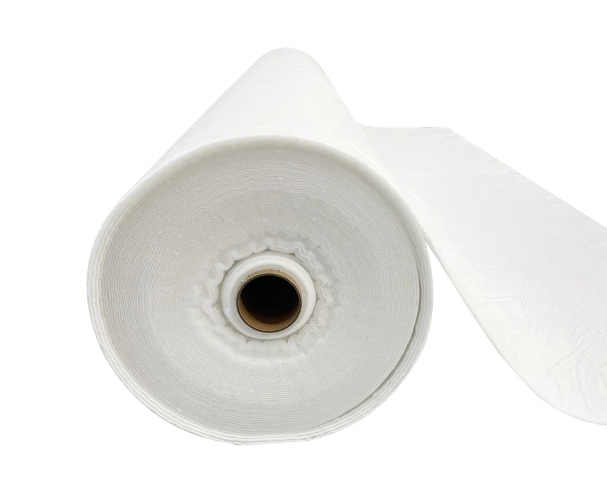
Assess any geotextile cushioning layer with the actual liner, aggregate, load and duration. A mass of 400 or 600 g/m² does not independently establish protection. Index puncture force in newtons is not a maximum safe stone size, water depth or vehicle weight. The Bureau of Reclamation geomembrane design reference provides background on support, protection and system-level design.
Calculate loads correctly, then assess the lining system
For a static liquid, pressure at depth is p = ρgh. Taking fresh-water density as 1,000 kg/m³ and g = 9.81 m/s², each metre of head adds approximately 9.81 kPa. Thus 10 m gives 98.1 kPa and 15 m gives 147.2 kPa. These are loads, not allowable pressures assigned to a liner thickness.
| Illustrative condition | Calculation | Interpretation |
|---|---|---|
| 20 m of material at 2,100 kg/m³ | 2,100 × 9.81 × 20 = 412 kPa | Simplified vertical overburden stress; actual geometry, pore pressure and stress distribution still require assessment |
| 0.5 m net water head below an empty liner | 1,000 × 9.81 × 0.5 = 4.91 kPa | Uplift must be resisted or relieved by the designed system |
| 1.5 mm sheet at 940 kg/m³ | 0.0015 × 940 × 9.81 = 13.8 Pa | Only 0.0138 kPa of self-weight; thickness is not a substitute for uplift control |
Groundwater drainage and gas management need a continuous flow path, outlets, maintenance access and appropriate design capacity. Cover material also has submerged-weight and stability considerations. Do not size ballast from dry bulk density alone.
For covered slopes, evaluate the actual material interfaces and stress range. Texture height or nominal thickness cannot certify a safe slope angle. ASTM D5321/D5321M concerns direct-shear assessment of soil–geosynthetic and geosynthetic–geosynthetic interfaces; project design determines how the results are used.
Allow for installation, maintenance and temperature
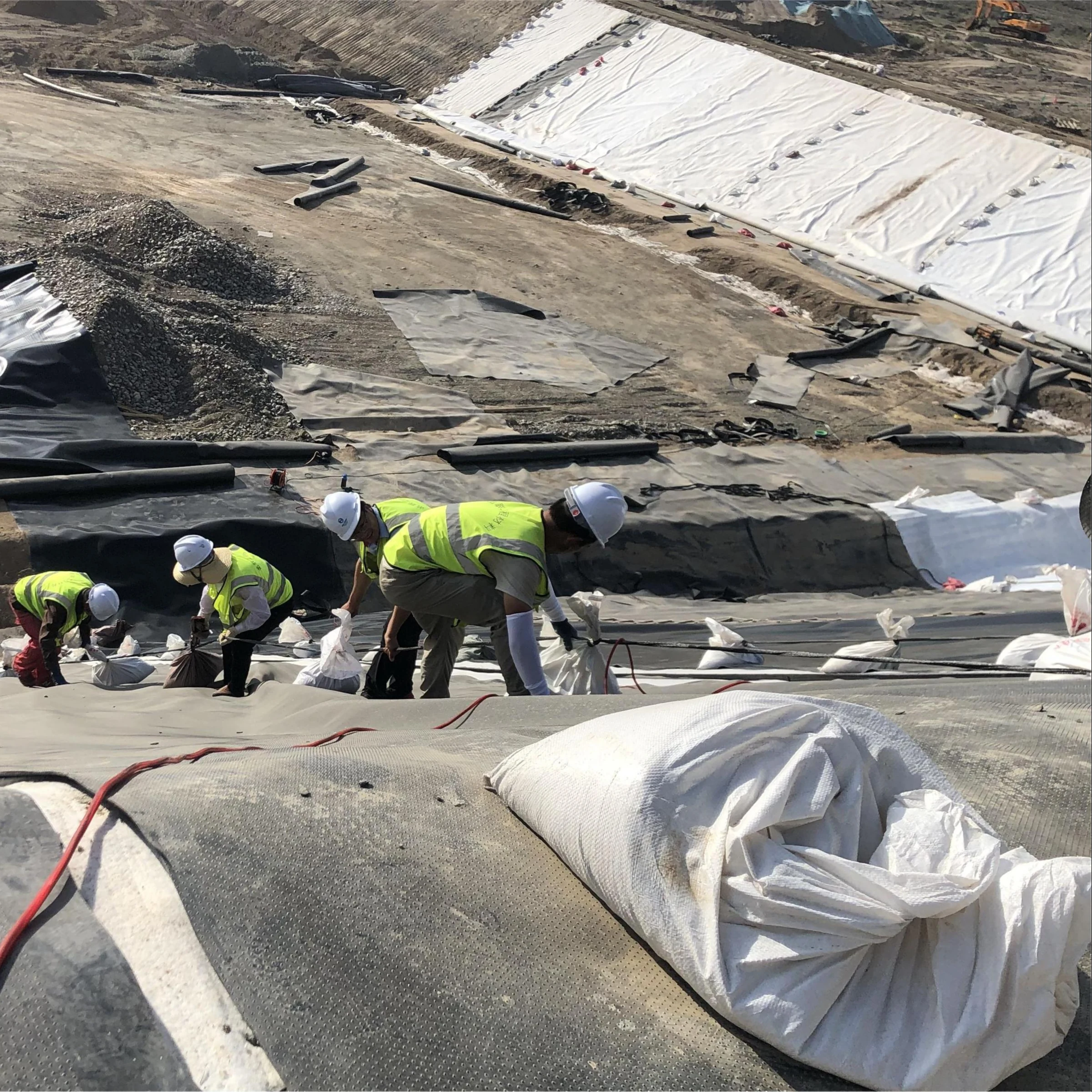
Keep equipment off exposed liner unless an approved system-specific procedure explicitly permits it. Cover placement, turning, braking, dropped aggregate, desilting and pump supports can create concentrated damage that a simple static-pressure calculation misses. Specify protection thickness and placement equipment through design and trials, not a universal table of liner thickness versus truck access.
A thermal-movement estimate is ΔL = αLΔT. If α is assumed to be 1.2 × 10⁻⁴/°C, a 100 m free strip subjected to a 50°C change has ΔL = 0.60 m. Actual restraint and measured material temperature affect movement; this calculation is not a prescribed slack allowance. Qualify welding under actual conditions rather than adopting one temperature and speed for all thicknesses.
Compare quantities and submit a complete specification
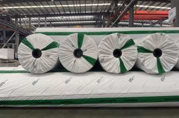
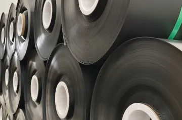
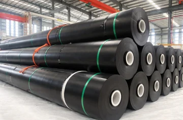
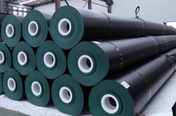
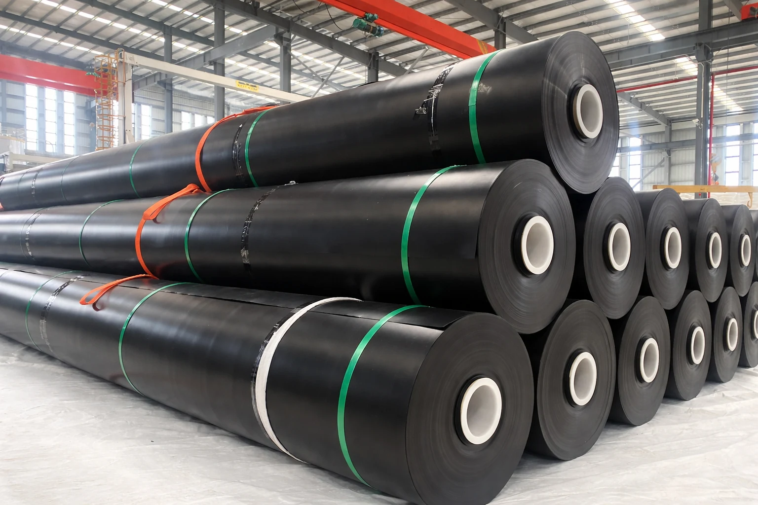
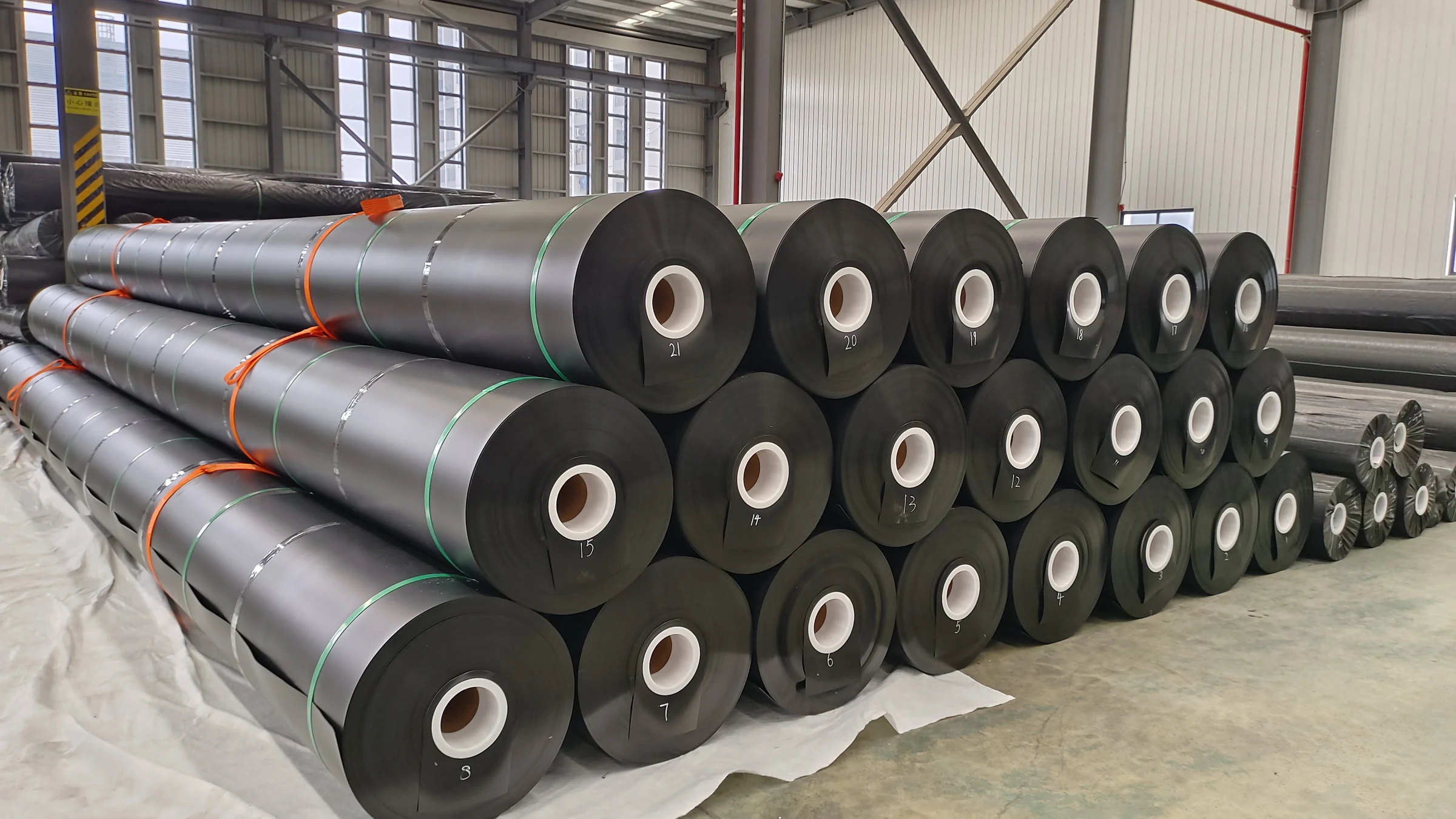
Approximate sheet mass per area is density × thickness. At an assumed 940 kg/m³, 1.0, 1.5, 2.0 and 2.5 mm sheets weigh approximately 0.94, 1.41, 1.88 and 2.35 kg/m². A hypothetical 7 m × 140 m roll of 2.0 mm sheet therefore contains about 1,842 kg of polymer before core and packaging. Verify actual gross weight and lifting requirements.
- Identify the liquid, temperatures, operating levels, service exposure and governing specification.
- Confirm foundation support, settlement, uplift, slopes and construction loads.
- Select the material family, nominal thickness, finish and tested protection system.
- Specify material acceptance, seams, penetrations, inspection and repair records.
- Calculate installed geometry, then add panel-layout overlaps, anchors and detail allowances.
Review the HDPE liner range and LLDPE alternatives against that specification. Send the drawings and required test schedule for a comparable proposal. No fixed service life follows from thickness alone.