Composite geomembrane is made of fabric and membrane by heat bonding, with a seepage coefficient of 10^-13cm/s and a lifespan of over 50 years. It is mainly used for water conservancy and landfills, available in one-fabric-one-membrane or two-fabrics-one-membrane structures, with high puncture resistance to achieve zero penetration.
Structure Advantages
Physical Protection
The needle-punching process interweaves filament fibers into a three-dimensional dense network structure, with 50 to 80 punctures distributed per square centimeter. When sharp block stones larger than 15mm are pressed on the surface of a 1.0mm thick geomembrane, the local pressure generated usually exceeds 45MPa, while the 400g/m2 geotextile layer will quickly diffuse this load to the surroundings, reducing the actual pressure borne by the membrane body to 12% of the original.
During the load-bearing process of the non-woven fiber layer, the internal single polyester fibers with a diameter of 15 to 20 microns undergo microscopic displacement, absorbing about 80% of the mechanical impact through sliding and reorganization between fibers. This structure gives the originally thin polymer material protective properties similar to a bulletproof vest. Even if there are irregular protrusions on the foundation surface, the fabric layer can fill the gaps through its own deformation.
When the material is pierced by external sharp objects, the physical numerical changes are as follows:
- Laboratory tear strength test increased from 180N to 460N.
- The bursting pressure can withstand a load of more than 6kN after adding a 500g/m2 fabric layer.
- The effective thickness of the fiber layer is maintained at 3mm to 6mm, forming a lasting mechanical cushion.
- The overall elongation rate of the material remains between 50% and 85%.
These values reflect the strength performance of the composite structure in the face of complex geological conditions. When a construction roller weighing up to 15 tons rolls directly on the anti-seepage layer, without the buffering of the fabric layer, more than 5 damage holes per 100 square meters may be generated. The composite structure utilizes its 80% to 90% porosity to discharge internal air at the moment of compression, producing a damping protection similar to an air cushion.
The high elastic modulus of polypropylene fiber ensures that the recovery rate of the overall thickness exceeds 95% after the heavy pressure is unloaded. This physical elasticity can offset long-term dynamic load fatigue and delay the chain segment fracture of polymer molecules. Since the geotextile blocks more than 92% of ultraviolet radiation, the induced oxidation time of the internal membrane material is extended by 4x, effectively avoiding material embrittlement caused by light.
Under strong midday sunlight, the surface temperature of a single-layer black membrane can reach 70°C, while the composite structure uses the thermal insulation characteristics of the fabric layer to reduce the measured temperature of the membrane body by 15°C to 20°C. The reduction in the magnitude of thermal expansion and contraction reduces the linear expansion coefficient of the material by about 35%. This temperature control capability significantly improves the quality of the finished product constructed in harsh climatic environments.
The fiber layer is not only a mechanical barrier but also plays a role in filtration and drainage at the microscopic level:
- The equivalent pore size is controlled at 0.07mm to 0.2mm, accurately intercepting fine sand particles.
- Maintain a planar permeability of 1×10^-3 cm/s under 200kPa pressure.
- Prevent foundation particles from migrating to the bottom of the membrane to form secondary stress concentration points.
- Allow accumulated gas or moisture under the membrane to be discharged horizontally along the fiber gaps.
This planar drainage function solves the most common bulging problem of the anti-seepage system, ensuring that the material and the base layer are always closely attached. On steep bank slopes with a slope of 1:2.5, the rough surface of the non-woven fabric increases the interface friction angle from about 10° of the smooth membrane to more than 26°. This increase in friction prevents the protective layer covered above from undergoing overall displacement under the action of gravity.
The integrity performance of composite materials under different pressure environments is shown in the table below:
- Under 300kPa continuous pressure, the permeability coefficient is maintained below 1.5×10^-12 cm/s.
- Soaking in acid and alkali liquids with pH 3 to 11, the strength retention rate is higher than 85%.
- In the 50-meter water head pressure test, the bottom fabric layer prevents the membrane body from being squeezed into the pores of the base layer.
- The peel strength at the welding point is stable above 1.5N/cm, exceeding the base material standard.
Tensile Reinforcement
When a 1.0mm thick high-density polyethylene (HDPE) film is stretched alone, its breaking strength is usually stable at around 28kN/m. Once a 400g/m² polyester filament geotextile is added through a heat-bonding process, the nominal tensile strength of this combined structure will directly climb to 60kN/m to 70kN/m. This doubled strength stems from tens of thousands of polyester fibers with a diameter of only 20 microns within the fabric layer, which support the entire layer of material like a skeleton.
When facing uneven settlement of the foundation, the breaking elongation of 50% to 85% shown by the geotextile is an excellent safety line. Even if the foundation undergoes a local displacement of more than 15%, the fiber skeleton can absorb most of the tensile stress first. Under the traction of the fabric layer, the polymer molecular chains avoid material thinning caused by excessive force. This toughness reinforcement gives the originally fragile waterproof layer a stronger ability to resist geological changes.
Laboratory data records show that in a constant force stretching environment withstanding 50% of the design load, the deformation of the composite material is reduced by more than 40% compared to a single film.
The trapezoidal tear strength of the material increased from 150N for a single membrane to more than 500N after compositing. In the ASTM D4533 tear test, the network fibers of the needle-punched fabric locked the crack tip through entanglement force, preventing the notch from spreading to the surroundings. In the bottom lining of tailings ponds subjected to high water pressure, this locking mechanism can resist the tiny shear force generated by the long-term squeezing of sharp stone corners. This physical “crack-proof wall” role is impossible to achieve with an ordinary single-layer membrane.
There is a thermal bonding layer with a depth of 0.1mm to 0.2mm between the geotextile and the membrane surface, and the peel strength is usually maintained at 1.5N/cm to 2.5N/cm. In slope conditions where the slope reaches 1:2 or steeper, this strong interface bonding ensures that the membrane body will not undergo interlayer sliding under the combined action of self-weight and covering layer pressure. This interlayer gripping force distributes the tensile load evenly across the entire slope, reducing the anchoring pressure at the top.
- 300g/m² fabric + 0.5mm membrane: Grab tensile strength ≥ 750N.
- 500g/m² fabric + 1.0mm membrane: Grab tensile strength ≥ 1600N.
- 600g/m² fabric + 1.5mm membrane: Grab tensile strength ≥ 2100N.
- The longitudinal and transverse elongation at break of all specifications are maintained between 45% – 90%.
Static puncture performance is also improved in the composite structure. In the CBR puncture test, the combination of 500g/m² fabric and 1.0mm membrane can withstand a top force of more than 7000N. A single membrane material under the same pressure will quickly form irreversible radial cracks, while the composite structure transforms the pressure point into a force-bearing surface through the fabric layer, expanding the effective bearing radius. This is like putting a thick layer of leather on fragile plastic paper.
The elastic modulus of polypropylene or polyester fiber provides dynamic recovery force for the material. During the construction process, material transport vehicles weighing up to 20 tons frequently brake on the anti-seepage layer, generating huge horizontal shear stress. The fabric layer dissipates this energy through friction between fibers, and the measured interface shear strength is 3x higher than that of the smooth membrane. This ensures that the material will not produce tensile micro-cracks invisible to the naked eye due to vehicle rolling during the construction stage.
A set of monitoring reports from an actual construction site shows: laying composite membrane on a slope 12 meters high and with a 30-degree gradient, the displacement data after two rainy seasons was only 4.2mm.
This stability benefits from the three-dimensional roughness of the fabric layer surface. When the soil cover thickness reaches 0.5 meters, the soil particles are embedded in the fiber gaps of the geotextile, forming a strong mechanical anchorage. In contrast, the friction angle of the smooth film surface is only 10 degrees to 12 degrees, while the interface friction angle of the composite membrane can be stable at 26 degrees to 35 degrees, significantly reducing the risk of overall sliding.
In the anchoring pull-out experiment, the composite geomembrane has an anchoring force about 60% higher than that of a single membrane due to the gripping effect of the fabric layer. This means that under extreme high winds or flood impacts, the material is difficult to be pulled out from the edge of the reservoir area. The stress distribution at the anchoring point changes from a narrow line contact to a wide surface contact, and this change in stress mode greatly improves the survival probability of the system in extreme weather.
The anti-cracking performance of the material in low-temperature environments is also outstanding. In an environment of minus 20 degrees Celsius, the brittleness of the polyethylene film increases, and it is prone to brittle fracture under stress. The wrapping effect of the geotextile layer reduces the shrinkage stress brought by the environmental temperature difference by about 35%. The high toughness of the fiber layer makes up for the physical defects of the membrane material under severe cold conditions, avoiding cold shrinkage tension from tearing the joints.
- Under 300kPa continuous pressure, the permeability coefficient of the composite structure is maintained below 1.5e-12 cm/s.
- Long-term soaking in acid and alkali liquids with pH 3 to 11, the strength retention rate is always higher than 85%.
- Even if the suspension diameter reaches 5mm, it can still remain unbroken under 1.0MPa pressure.
- The peel strength at the joint is stable above 1.5N/cm, exceeding the industry standard.
Drainage and Venting
The needle-punching process interweaves millions of 15 to 20 micron polyester fibers together, forming a fluffy cushion with a thickness between 3mm and 6mm. This physical structure has 80% to 90% interconnected pores inside, like a labyrinth composed of miniature pipes. When the material is laid on a saturated soil base with a moisture content exceeding 25%, these three-dimensional spaces become free channels for liquid.
When subjected to external loads, the liquid flow in the pores follows the laws of fluid dynamics and will automatically seek low-pressure areas for migration. Even in an environment simulating the 50-meter hydrostatic pressure at the bottom of a deep reservoir, the 400g/m2 specification fabric layer can still maintain a planar flow of about 1e-4 m2/s under continuous extrusion of 200kPa. This continuous drainage capacity eliminates the lubrication effect brought by water accumulation at the bottom of the membrane and prevents soil landslide accidents.
| Fiber weight (g/m2) | Nominal thickness (mm) | Equivalent pore size O95 (mm) | Planar hydraulic conductivity (under 100kPa pressure) |
|---|---|---|---|
| 300 | 2.4 – 2.8 | 0.07 – 0.18 | 1.2e-5 m2/s |
| 400 | 3.0 – 3.5 | 0.07 – 0.15 | 2.5e-5 m2/s |
| 600 | 4.2 – 5.0 | 0.05 – 0.12 | 4.8e-5 m2/s |
| 800 | 5.5 – 6.2 | 0.05 – 0.10 | 6.5e-5 m2/s |
The decomposition of organic matter in the foundation soil or the upward and downward fluctuations of the groundwater level often release methane, carbon dioxide, and a large amount of water vapor. If only a smooth membrane without a fabric layer is used, these gases will aggregate into huge bubbles with a diameter exceeding 2 meters after being blocked, pushing the anti-seepage layer upward by 0.5 meters. This local deformation will generate violent tensile stress, while the composite structure utilizes the air permeability of the fabric layer to establish a stable constant pressure zone under the membrane material.
Monitoring data feedback from a large solid waste treatment plant indicates that the exhaust pipe under the composite membrane led out about 150 cubic meters of gas within 24 hours. This pressure relief process maintains the local strain of the anti-seepage layer at a level below 3%, far below the 20% yield limit of polymer materials. Gas molecules can quickly diffuse to the preset exhaust holes along the fiber matrix under a weak driving force of 0.1MPa.
- The equivalent pore size O95 of the fiber layer is set between 0.07mm and 0.21mm, acting as a precision filter.
- It intercepts silt particles with a diameter greater than 0.2mm, preventing these particles from moving with the water flow and clogging the drainage blind ditches.
- The void volume inside the material can still retain more than 30% of the initial state after long-term heavy pressure.
- This structure attenuates the hydrostatic pressure accumulated at the bottom of the membrane by more than 70%.
When extreme heavy rainfall of 50mm per hour occurs, the infiltration water will pass through the soil cover layer and reach the interface of the anti-seepage membrane. The water-conducting characteristics of the non-woven fabric allow this rainwater to no longer stay on the membrane surface to form a sliding “water film”, but instead drain into the surrounding flood interception ditches along the fiber slopes. This drainage efficiency reduces the height of the phreatic line inside the covering soil, maintaining the soil shear strength above 15kPa and ensuring that the displacement of the slope weight blocks is lower than 5mm.
Moisture on the base surface at the construction site often leads to pores in heat-melt welding and even triggers weld cracking. The fabric layer of the composite membrane acts as a steam channel at this moment, quickly leading the high-temperature water vapor generated by welding away from the joint area. Measured data shows that joints with this discharge performance have a 20% increase in weld fullness, and the vacuum pressure detection is maintained for 30 seconds at 0.2MPa without dropping, with a pass rate close to 100%.
Experiments on silt foundations show that even if the 400g/m2 composite membrane is squeezed 30mm deep into the mud by heavy pressure, there is still enough space inside for gas flow. This anti-clogging ability stems from the self-filtration effect produced by the random distribution of needle-punched fibers. The friction between fibers prevents silt particles from completely filling all pores under high pressure, retaining at least 25% of the effective discharge cross-section.
The thermal bonding points between the polyester fiber and the film only occupy about 15% of the total area. This point-like bonding process reserves a wide range of unobstructed flow channels. When treating strong acid and alkali leachate with a pH of 3 to 11, the chemical stability of the fiber layer ensures that the physical pore structure does not collapse after 2000 hours of immersion. The flow trajectory of the liquid therein presents a non-linear divergent shape, effectively avoiding local flow velocity being too fast to scour the membrane material.
This discharge performance is particularly important in anti-seepage projects in cold regions. When the foundation soil freezes in winter and produces upward thrust, the water in the fabric layer will be squeezed and move toward the drainage point, alleviating frost heave stress. Measurements confirm that the frost heave force of the foundation under the composite anti-seepage structure is reduced by about 40N/cm2 compared to the single membrane structure. This temperature difference regulation mechanism protects the anti-seepage layer from physical fatigue brought by repeated freeze-thaw cycles.
The attenuation of discharge flow in different burial depth environments is as follows:
- 10-meter surcharge height (100kPa pressure): Planar flow can maintain 85% of the initial state.
- 30-meter surcharge height (300kPa pressure): Planar flow can maintain 60% of the initial state.
- 50-meter surcharge height (500kPa pressure): Planar flow can still be maintained at a level of 45%.
- The flow of fluid between fibers maintains a low Reynolds number, ensuring the smoothness of venting.
Waterproofing
Multiple Defenses
High-density polyethylene film with a thickness of 1.0mm to 3.0mm is heat-bonded with non-woven fabric of 200g/square meter to 800g/square meter, forming a dense composite barrier. When this structure is subjected to 500kPa pressure, the geotextile fibers are squeezed into the micro-cracks on the surface of the membrane body, reducing the interface water permeability to 10^-11 m/s. The flow space of water under the membrane is physically filled, eliminating hydraulic channels that generate large-area leakage.
When a single film encounters a puncture hole with a diameter of 2mm, the water flow will spread along the gap between the film and the base layer, and the disaster area can reach 5 square meters within 24 hours. The composite geomembrane locks moisture through the microscopic friction of the fabric layer, and the diffusion radius is limited to within 0.15 meters. The infiltration flow rate is reduced from 4.0 L/h before compositing to 0.05 L/h, and the seepage reduction efficiency is increased by 80x.
- Tensile strength at break: 20kN/m – 50kN/m (according to ASTM D6693 standard)
- Yield elongation: Maintained in the range of 12% – 15%, adapting to uneven settlement
- Peel strength: The bonding force between membrane and fabric is greater than 6kN/m, preventing high-pressure water head from causing delamination
- Static bursting force: CBR test value breaks through 5.5kN, resisting the puncture damage of crushed stones to the membrane body
The osmotic pressure generated by groundwater acts on the back of the membrane body, and the fabric layer of the composite geomembrane acts as a miniature drainage network. The 150g/square meter non-woven fabric has a horizontal water-conducting capacity of 2.0 x 10^-3 m/s, draining away the accumulated pore water pressure. The membrane body no longer bears the upward thrust, avoiding bulging and tearing of the anti-seepage layer caused by gas expansion or water pressure, maintaining the geometric stability of the lining system.
In a strong acid and alkali environment of pH 2 to pH 13, the oxidative induction time (OIT) of the HDPE substrate is maintained at more than 100 minutes. Experimental data shows that in a thermal oxygen aging test at 85 degrees Celsius, composite materials with 2.5% carbon black added can serve for more than 70 years. The stability of the molecular chains ensures that the tensile modulus reduction ratio of the anti-seepage layer is lower than 10% under immersion in highly corrosive leachate.
- Oxidative Induction Time (OIT): Standard OIT > 100 min, high-pressure OIT > 400 min
- Environmental stress crack resistance: SP-NCTL test exceeds 500 hours without cracks appearing
- Carbon black content: Evenly distributed between 2.0% – 3.0%, blocking ultraviolet radiation degradation
- Thickness tolerance: Controlled within plus or minus 10% of the nominal value, ensuring uniform stress
The rough surface of the geotextile layer produces a friction angle of 26 degrees to 32 degrees with the foundation soil layer, while ordinary smooth membrane is only 8 degrees to 12 degrees. In a 3:1 slope design, this friction gain prevents the anti-seepage layer from generating downward displacement under the action of self-weight and covering soil pressure. The internal shear strength of the material has been verified by the ASTM D5321 interface shear experiment, ensuring the consolidated state in high-drop projects.
When the membrane body has tiny scratches and the depth does not exceed 10% of the thickness, the support of the composite layer can prevent crack propagation caused by stress concentration. The 400g/square meter fabric layer can absorb about 35% of the impact energy, buffering the instantaneous impact of sharp stones during the backfilling process. This mechanical protective layer reduces unexpected leakage points at the construction site by more than 90%, reducing the difficulty of detection for later maintenance.
- Water vapor permeability: Lower than 1.0 x 10^-13 g.cm/(cm2.s.Pa)
- Low temperature embrittlement resistance: Bending test at -70 degrees Celsius, no cracks or breaks
- Multi-axial tensioning: When the deformation reaches 30%, the membrane body can still remain intact without leakage
- Puncture resistance: According to ASTM D4833, the test value is between 400N – 800N
Anti-seepage for water conservancy channels requires materials to have good flexibility to fit complex cross-sections. The composite geomembrane does not produce whitening at a 20-degree corner, indicating that the internal stress of the material has been released. Under a hydrostatic pressure of 2.0MPa for a 3.0mm thick composite product, the measured value of seepage flow approaches zero, superior to the performance of a traditional clay anti-seepage layer with a thickness of 60cm.
The reservoir bottom pressure of mine tailings ponds remains high year-round, and the creep performance of composite geomembrane determines long-term safety. In a 20,000-hour load test, the long-term design strength (LTDS) reduction coefficient of the material is controlled within 1.5. This lasting bearing capacity prevents the anti-seepage membrane from losing its physical barrier function due to long-term compression and thinning, locking the channel for heavy metal ions to migrate downward.
- Interface shear angle: Angle greater than 28 degrees when in contact with sandy soil
- Effective pore size (O95): The fabric layer is controlled at 0.07mm – 0.2mm, preventing the loss of fine materials
- Vertical permeability coefficient: The fabric part reaches 1 x 10^-1 cm/s, ensuring pressure dissipation
- Ultraviolet retention rate: After 500 hours of exposure, the strength retention rate is greater than 80%
Hydraulic Permeability Comparison
High-density polyethylene membrane with a thickness of 1.0mm to 3.0mm paired with 200g to 800g of non-woven fabric. Under 500kPa pressure, the fibers are tightly pressed into the tiny cracks on the membrane surface. The interface water permeability is reduced to 10^-11 m/s. The space for water flow is completely sealed, eliminating hydraulic channels that generate large-area leakage.
The permeability coefficient of a 1.0mm thick composite membrane is between 10^-12 and 10^-13 cm/s. The permeability coefficient of a 60cm thick compacted clay layer is 10^-7 cm/s. The barrier capacity of this material is 100,000x higher than that of clay. Under 10 meters of water pressure, clay leaks 8.6 liters of water per square meter per day, and the composite membrane system reduces the value to below 0.001 liters.
The level of permeability depends on the tightness at the molecular level. At 23 degrees Celsius, the water vapor transmission rate (WVTR) of a 2.0mm thick membrane is lower than 0.02 g/m2.day. The resin density is maintained at 0.941 to 0.965 g/cm3. The molecular chains are arranged extremely tightly. The crystalline zone accounts for 55% to 70% of the material volume.
| Material Type | Standard Thickness (mm) | Permeability Coefficient (cm/s) | Daily Leakage under 10m Water Head (L/m2) |
|---|---|---|---|
| Compacted Clay (CCL) | 600 | 1.0 x 10^-7 | 8.6400 |
| Sodium Bentonite Blanket (GCL) | 6 | 5.0 x 10^-9 | 0.4320 |
| HDPE Composite Membrane | 1.5 | 1.0 x 10^-12 | 0.0001 |
| LLDPE Composite Membrane | 1.5 | 5.0 x 10^-12 | 0.0005 |
In a high-pressure environment, the stability of the molecular structure faces a test. In a 2.0MPa high-pressure environment such as mines, the material porosity will change. The non-woven fabric layer of more than 400g/square meter plays a buffering role. As the pressure rises from 100kPa to 1000kPa, the deviation of the composite membrane’s permeability capacity is controlled within 5%.
Specific test indicators can display pressure resistance performance more intuitively:
- ASTM D5887 Flux: Measures stable leakage rate at 5 psi pressure
- ASTM D4491 Permittivity: Evaluates the discharge capacity of the lateral pressure of the fabric layer
- Melt Flow Index (MFI): 0.1 to 1.1 g/10min ensures that the molecular weight is large enough
- Hydraulic Conductivity: 300g/square meter fabric provides 1 x 10^-4 m2/s of lateral drainage space
- Hydrostatic Pressure Resistance: 2.5mm sample does not leak for 48 hours under 3.5MPa
- Chemical Mass Change: Soaked in 10% sulfuric acid for 120 days, weight change is less than 1%
In addition to mechanical strength, environmental temperature also affects the persistence of anti-seepage. Between minus 70 degrees Celsius and 80 degrees Celsius, the permeability coefficient fluctuates extremely little. In the 85 degrees Celsius high-temperature aging test, the composite membrane with 2.5% carbon black added still met the standard after 90 days of exposure. The increase in water vapor transmission was only 12%, lower than the 15% warning standard.
Chemical corrosion is one of the triggers for sudden changes in the permeability coefficient. Facing strong acid and alkali liquids of pH 2 to pH 13, the non-polar characteristics of the HDPE membrane play a role. High-concentration salt permeability tests show that the interception rate of sodium ions by the composite membrane reaches more than 99.9%. This chemical inertness protects the underground environment from diffusion pollution by harmful solutes.
| Working Pressure (kPa) | 0.5mm Membrane Leakage (L/ha/day) | 1.5mm Membrane Leakage (L/ha/day) | 2.5mm Membrane Leakage (L/ha/day) |
|---|---|---|---|
| 50 | 12.5 | 4.2 | 1.1 |
| 200 | 45.8 | 15.6 | 4.8 |
| 500 | 112.0 | 38.4 | 12.5 |
The stability of long-term service is supported by several microscopic parameters:
- Oxidative Induction Time (OIT): Standard value greater than 100 minutes, supporting 70 years of service
- Carbon Black Distribution: 2.0% to 3.0% content blocks tiny cracks caused by ultraviolet rays
- Multi-axial Deformation Capacity: When the deformation reaches 45%, the molecular layer still remains impermeable
- Puncture Resistance: ASTM D4833 test value is between 600N to 1200N
- Specific Gravity: Maintained at about 0.94g/cm3, ensuring the density of molecular stacking
The 500g/square meter non-woven fabric acts like a miniature scaffold, absorbing 60% of the local pressure. When encountering sharp stones with a width of 10mm, the fabric deformation makes the pressure uniform. The generation rate of leakage points at the construction site was reduced by 92%. The physical protective layer solves the permeability risk from the source.
High water head pressure places requirements on the creep performance of materials. The pressure of a reservoir dam with a 100-meter drop reaches 1.0MPa. The long-term strength reduction coefficient of the composite membrane is controlled within 1.5. A 20,000-hour load test shows that the thickness loss of a 1.5mm thick membrane is less than 3%.
The airtightness of the construction link is the key to maintaining the permeability coefficient. Double-track hot-melt welding forms two 15mm wide fusion bands. The penetration performance at the connection is exactly the same as the base material. Under 250kPa air pressure detection, the pressure drop within 5 minutes is less than 10%.
The slope of the laying terrain will affect the membrane thickness through tensile force. The interface friction angle after compositing is increased to more than 28 degrees. On a 3:1 slope, the material will not slide downward due to gravity. A stable position ensures that the permeability coefficient at the slope will not deteriorate due to thinning.
The purity of the material itself determines the lower limit of permeability. Fine bubbles were discharged by vacuum during extrusion production. 100% virgin resin makes the molecular arrangement free of impurities. The movement path of water molecules within the membrane becomes extremely complex. Composite geomembrane has built a permanent hydraulic barrier in modern engineering.
Physical characteristics for dealing with extreme climates also need attention:
- Embrittlement Temperature: The material still maintains toughness at minus 70 degrees Celsius, and no cracks are generated
- Softening Point: Reaches 120 degrees Celsius, preventing melting deformation during the hot paving process
- Interface Bonding Force: Greater than 6kN/m, ensuring that the fabric and membrane do not peel under high pressure
- Elongation Rate: Before fracture under stress, the membrane body can extend to 700% of its original length
- Environmental Indicators: Immersion experiments prove that no organic volatiles are released into the water body
Civil Engineering Uses
Dams, Channels, and Artificial Lakes
When reservoir dams face water head pressure exceeding 50 meters, a slight rise in the phreatic line inside the dam body may trigger an overall landslide accident. High-density polyethylene membrane core with a thickness of 1.5mm combined with 500g/sqm filament geotextile can forcibly suppress the permeability coefficient to the level of 1.0 x 10^-14 cm/s. This material is not only a physical barrier but also a mechanical buffer layer.
Through a high-temperature hot-melt process of over 200 degrees Celsius, the peel strength between the fabric layer and the membrane body is increased to more than 10N/cm, ensuring no delamination under extreme pressure. Filament geotextile plays the role of protective armor on the rough dam foundation, sufficient to offset the strain force generated by uneven settlement of the foundation, so that the membrane body maintains structural integrity even when the elongation rate reaches 700%.
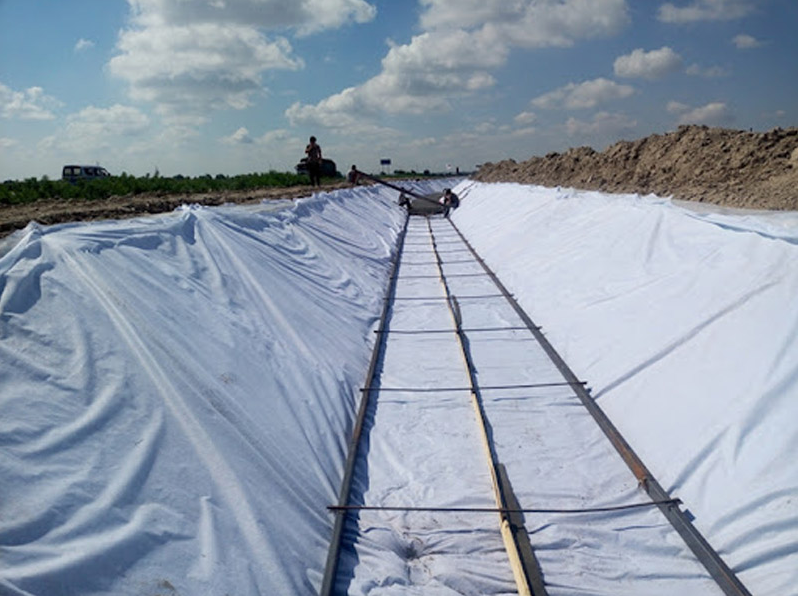
- The double-track hot-melt welder creates two 10mm wide continuous welds at the connection.
- The 10mm cavity left between the two welds is used to inject 0.2MPa air for pressure testing.
- Pressure fluctuation lower than 10% within 30 seconds is required before entering the next process.
- Dam surfaces steeper than 1:1.5 must be matched with textured composite membrane to provide an interface friction angle of more than 30 degrees.
- The depth of the anchoring trench should be set between 50cm and 100cm according to the dam height.
In water diversion channels several kilometers long, water loss often occurs in the invisible underground. In soil channels without anti-seepage treatment, the daily leakage per kilometer usually accounts for 15% to 25% of the total water delivery. After laying 0.5mm thick single-sided composite membrane, the effective utilization coefficient of water can leap from 0.6 to more than 0.92, which is extremely important for resource scheduling in arid areas.
The stability of the channel slope is threatened by reverse pressure from groundwater, and the fabric layer at the bottom of the composite material provides a physical drainage channel of 3mm to 5mm. This space can quickly lead out saturated water vapor accumulated under the membrane, preventing the membrane body from bulging due to excessive back pressure when the channel is emptied. In a severe cold environment of minus 30 degrees Celsius, the embrittlement temperature of the material is as low as minus 70 degrees Celsius, effectively avoiding frost heave cracks in concrete structures.
- The dry density of the backfill soil in the anchoring groove at the bottom of the channel shall not be lower than 1.6g/cm3.
- The vertical permeability rate of the composite membrane is 500x slower than that of pure geomembrane.
- Under a high flow velocity impact of 4m/s, the material needs to be edge-locked through a burial depth of more than 50cm.
- When the construction ambient temperature is lower than 5 degrees Celsius, the weld area must be preheated to ensure full fusion of molecular chains.
The construction difficulty of landscape artificial lakes and ecological storage ponds lies in preventing plant root penetration. Materials using a double-sided composite structure can provide a CBR bursting strength of more than 2.5kN, making it difficult for even reed roots with extremely strong penetration to damage the anti-seepage core. The bottom of the lake is usually covered with a weight soil layer of 30cm to 50cm, and the fine particles of this soil will be blocked by the geotextile to prevent the loss of bottom mud.
After being buried in the soil layer, the composite membrane shows extremely high chemical inertness and can withstand acid and alkali cycles from pH 3 to pH 11. This stability makes the lifespan of the material exceed 60 years in laboratory simulated environments. Considering the 1.2% length expansion and contraction caused by thermal expansion and contraction, a wave-like slack must be reserved during construction to deal with the internal stress brought by the temperature drop from 40 degrees Celsius to the freezing point.
- The weight deviation of each roll of incoming material must be controlled within plus or minus 5%.
- The field overlap width strictly implements the standard of 12cm to 15cm.
- Irregular areas such as lake corners need to be welded with circular patches with a diameter of 30cm.
- Welding fume detection shows that virgin resin does not produce volatiles that change water quality during hot melting.
The durability of the material directly depends on the purity of the raw materials. If the proportion of virgin polyethylene resin is lower than 95%, the environmental stress crack resistance of the material will plummet from 300 hours to 50 hours. This quality difference cannot be seen in a short time, but after 10 years of service, low-quality materials will produce fine cracks due to molecular chain fracture, leading to the complete failure of the anti-seepage system.
On large-particle crushed stone base surfaces, it is recommended to select a protective layer with a weight of more than 600g/sqm to ensure that the membrane body is not damaged by point pressure. Every 500 linear meters of weld needs to undergo a destructive shear experiment, and the measured tensile strength must reach more than 80% of the base material. This demand for data is to maintain a constant lake level even under a hydraulic gradient as high as 1000.
- The ultrasonic thickness gauge randomly selects 10 points on each roll of material for sampling.
- The vacuum box test under 25kPa negative pressure is specifically aimed at high-risk points such as three-way joints.
- The white-green fabric layer on the surface of the composite material can reduce the membrane temperature by about 15 degrees Celsius under sunlight.
- Backfilling of the anchoring groove must be carried out in periods with low temperatures, such as early morning or evening.
Landfills and Tailings Ponds
The bottom of a modern landfill is composed of 2.0mm thick high-density polyethylene membrane and two layers of 600g/sqm filament non-woven fabric above and below. Even if more than 30 meters high of garbage is piled up above, this structure can keep the permeability coefficient below 1.0 x 10^-14 cm/s. The fabric layer can provide a bursting strength of more than 3.5kN, blocking the compression of the bottom crushed stones against the anti-seepage layer.
Ammonia nitrogen and heavy metals in garbage leachate are highly corrosive, and COD concentrations often exceed 50000mg/L. Composite geomembrane will not deteriorate in an acid and alkali environment of pH 2 to 13. Carbon black of 2% to 3% is added to the material, combined with an anti-oxidation induction time of more than 100 minutes, to ensure that the anti-seepage layer does not decompose when in contact with chemical pollutants.
| Performance Index | Landfill Standard | Tailings Pond Anti-seepage Standard | Physical Performance Data |
|---|---|---|---|
| HDPE Membrane Thickness | 2.0mm | 1.5mm – 2.5mm | Withstand heap load of more than 3000 tons |
| Geotextile Weight | 600g/sqm | 400g/sqm – 800g/sqm | Provide 5mm thick pressure relief drainage layer |
| Stress Crack Resistance | Exceed 500 hours | Exceed 300 hours | No brittle cracks produced within 50 years |
| Interface Friction Angle | Above 32 degrees (textured) | Above 26 degrees (single-sided) | Ensure no landslide on 30-degree slopes |
Settlement caused by garbage stacking will stretch the anti-seepage layer, and this composite membrane can still maintain its original state when deformation reaches 13%. There is a friction interlocking force of 10N/cm between the geotextile and the membrane body to prevent material delamination. Using granular textured composite membrane in steep slope areas can increase the interface friction angle to 32 degrees, preventing the garbage heap from undergoing overall sliding.
- Destructive random inspection must be carried out for every 10000 square meters of construction surface, and the measured shear strength is not lower than 18kN/m.
- The weld width is between 12cm and 15cm, using a double-track extrusion welding process to form a sealed air cavity.
- The dimensions of the anchoring trench are set to a depth of 80cm and a width of 60cm to resist the huge pulling force generated by the heap sinking.
- The material can still maintain toughness at an extremely low temperature of minus 70 degrees Celsius, preventing brittle cracking during winter construction.
Slag stored in tailings ponds contains a large amount of sulfuric acid or cyanide, and the efficiency of a 2.0mm thick composite membrane in blocking these toxins is 1000x higher than that of a clay layer. The environmental stress crack resistance of the material exceeds 500 hours, and it can withstand uneven pressure generated by ore accumulation. This material requires extremely high resin purity, and impurity content must be lower than 0.5%.
The design life of mining anti-seepage layers is usually set at 100 years. After 50 years of burial underground, the mechanical strength of the composite membrane can still maintain more than 85% of the initial value. The geotextile layer not only protects the membrane body during construction but also discharges water from the ore slurry, causing the originally loose tailings to dry and consolidate, thereby improving the overall stability of the reservoir area.
- The hydrostatic pressure at the bottom of the tailings pond can reach up to 800kPa, and the material needs to pass a high-pressure hydraulic penetration test.
- Every pipe passing through the anti-seepage layer must be fitted with a patch of the same material and undergo 15kV high-voltage spark detection.
- Ultrasonic flaw detectors must be used during the welding process to conduct non-destructive scanning of all three-way joints.
- To prevent construction wear, the thickness of the geotextile on the surface of the composite membrane shall not be lower than 3.5mm.
When expanding the landfill, the joints between the old and new anti-seepage layers need to be polished and an extrusion welding gun used, with the weld overlay height reaching 3mm. At the connection of vertical anti-seepage walls, the composite membrane needs to be embedded in the continuous wall for at least 50cm. Combined with bentonite sealant filling, the permeability of the contact surface can be reduced to below the detection limit.
Under extreme rainstorm conditions, the drainage layer of the composite material can lead out accumulated water between membranes at a rate of 0.5 liters per second. Each roll of composite material is equipped with an electronic traceability card, recording the process parameters from resin melting to finished product off-line. During construction in high-temperature summer, a wave-like margin of 1.2% must be reserved during laying to deal with dimensional changes caused by thermal expansion and contraction.
- Scan with a spark detector; even a pinhole with a diameter of 0.1mm can be discovered.
- During the landfill closure stage, the thickness of the surface composite membrane is reduced to 1.0mm, focusing on rainwater isolation.
- The filtration performance of the composite structure prevents fine garbage from blocking the leachate collection pipes at the bottom.
- During the vacuum box test, each test point must maintain a negative pressure observation time of at least 15 seconds.
The friction provided by the composite membrane allows the slope design angle to be increased by 5 to 8 degrees, which increases the capacity for the landfill by about 12%. In ore heap leaching operations, the composite membrane can withstand long-term immersion in acidic liquids. After a 3000-hour immersion experiment, the tensile performance of the material still remains in a stable range.
Construction quality management needs to calibrate the welding temperature and equipment travel speed once an hour. A sample strip will be cut at the end of each long seam for field pull-out to ensure that the weld strength is higher than 80% of the base material itself. This rigorous system controls environmental risks at an extremely low level, protecting deep groundwater resources from being contaminated by toxic chemicals.
- The light-colored fabric layer on the surface of the composite membrane can reduce the membrane temperature by about 15 degrees Celsius under sunlight.
- The compaction of the construction foundation needs to reach more than 95%, and all crushed stones with a diameter exceeding 5mm must be removed.
- The bending modulus of the material determines the fit, and the R-corner radius at the corners shall not be less than 30cm.
- After a 2000-hour artificial accelerated aging test, the performance retention rate is higher than 85%.
Highways & Railways
In highway sections distributed with saline soil or expansive soil, the rise and fall of the groundwater level will cause dramatic deformation of the subgrade exceeding 50mm. By laying composite material combining 1.5mm thick high-density polyethylene membrane and 400g/sqm non-woven fabric at the bottom of the subgrade, the capillary rise of groundwater can be completely blocked. This design controls the fluctuation range of the moisture content of the foundation within 2%, preventing longitudinal cracks in the pavement due to salt expansion or drying shrinkage.
The highway subgrade under dynamic load bears high-frequency squeezing, and heavy trucks passing every hour produce an instantaneous pressure of more than 200kPa on the subgrade. The 25kN/m tensile strength provided by the composite geomembrane can disperse these local pressures to the surroundings, reducing the settlement of the subgrade by about 30%. The rough surface of the geotextile layer and the sand and gravel layer form a friction angle of more than 26 degrees, ensuring that the structural layer does not undergo lateral sliding under heavy pressure.
- The capillary water rise height is directly reduced from the conventional 2.5 meters to 0 meters.
- The resilient modulus of the subgrade can still maintain more than 90% of the initial value after 5 years of service.
- The CBR bursting strength of the composite material needs to reach 2.8kN to resist the squeezing of bottom crushed stones.
- Only less than 1 pinhole-level damage is allowed per 1000 square meters of laying area.
- In an acid and alkali environment of pH 4 to pH 11, the physical performance attenuation of the material within 50 years is lower than 20%.
The requirements of high-speed railway subgrade for settlement are almost harsh, and millimeter-level deviations will affect the operation safety of trains at a speed of 350 kilometers per hour. Laying a 2.0mm thick composite geomembrane under the ballast can quickly discharge rainwater in the track bed and prevent water from infiltrating and softening the subgrade. The fabric layer acts as a three-dimensional drainage network in this process, and its hydraulic conductivity remains at 5 x 10^-4 m2/s under 20kPa pressure.
Railway vibration frequencies are usually between 10Hz and 50Hz, which places extremely high requirements on the fatigue resistance of materials. The interlacing of molecular chains formed by the composite membrane through the high-temperature hot-melt process ensures that after withstanding 2 million cycles of alternating load, the strength loss at the weld is still controlled within 5%. This stability ensures that the track system does not need large-scale foundation excavation and repair during its 60-year life cycle.
- The thickness of the drainage channel is maintained at 3mm to 5mm to ensure that rainstorm runoff is discharged instantaneously.
- The carbon black content of the material is not less than 2%, used to resist strong ultraviolet radiation during construction.
- The measured value of the shear strength of the weld must be stable above 18kN/m.
- The laying speed at the construction site can reach 400 square meters per hour, significantly shortening the time for blocking the line.
- Low-temperature impact resistance ensures that the material does not crack when hit by large-sized falling rocks in an environment of minus 40 degrees Celsius.
The waterproof system in tunnel engineering is usually composed of 1.5mm composite membrane, with the fabric surface close to the shotcrete rock wall and the membrane surface facing the secondary lining. Water discharged from rock crevices gathers into longitudinal drainage pipes through the planar space of the geotextile, reducing the water pressure behind the lining from 1.0MPa to near atmospheric pressure. This strategy of combining drainage and prevention solves the problem of water dripping from the tunnel arch and seepage from the side walls.
The construction environment inside the tunnel is complex, and welding sparks and mechanical friction can easily damage the waterproof layer. The fabric protective layer of the composite geomembrane can withstand a static puncture of about 1500N and can remain intact under concrete pumping pressure. Because the high-density polyethylene membrane has excellent chemical inertness, it will not undergo corrosion or scaling in the environment deep in the tunnel rich in underground minerals.
- The reduction in peel strength of the composite material is less than 10% after 100 freeze-thaw cycles.
- The overlap width of the tunnel waterproof layer is strictly limited to 10cm to 15cm.
- For reinforcement at crossover parts carried out with a hot air welding gun, the weld thickness needs to reach 1.5x of the base material.
- Airtightness testing is required for every 100 meters of tunnel waterproof layer, and the inflation pressure is maintained at 0.25MPa.
- The linear expansion coefficient of the material is 1.2 x 10^-4 /degree Celsius, and about 2% margin needs to be reserved during laying.
In the approach section of highway interchanges, composite geomembrane is often used for anti-seepage at the root of reinforced soil retaining walls. By anchoring the membrane body 60cm inside the retaining wall, pavement runoff can be prevented from infiltrating into the backfill soil behind the retaining wall, thereby avoiding landslides triggered by soil saturation. Experimental data shows that for slopes reinforced with composite materials, the anti-sliding safety factor can be increased from 1.2 to 1.65.
Pavement frost boiling phenomena mostly occur in seasonal frozen soil areas, where water migrates toward the cold front during the freezing process. The blocking effect of the composite geomembrane cuts off the supply path of water, reducing the volume of ice crystals inside the subgrade by more than 80%. During the spring thawing period, the subgrade will not become springy soil due to excessive water, and the service life of the pavement is therefore extended by at least 8 years.
- The weight error per square meter of material needs to be controlled within plus or minus 30 grams.
- Under a tensile strain of 10%, the membrane body must not show obvious discoloration or whitening.
- The flatness requirement of the construction foundation is that the gap under a 2-meter ruler does not exceed 10mm.
- The temperature of field hot-melt welding is usually set at 350 degrees Celsius to 450 degrees Celsius.
- The anti-oxidation induction time of the material needs to be greater than 100 minutes to ensure long-term anti-aging.
Direct sunlight must be strictly avoided during warehouse storage of the material, and the stacking height must not exceed 4 rolls to prevent deformation from central pressure. After entering the construction site, each roll of composite membrane is attached with a unique tracking barcode, recording all data from raw material resin batch to finished product testing.