Hot Wedge Welding for large area double-track seams (350-400℃, 1-2m/min). Extrusion Welding for corners and damage repair. Quality Testing includes Non-Destructive Testing (such as double-seam air pressure testing, usually inflated to 200kPa and maintained for 5 minutes to observe pressure drop) and Destructive Testing (sampling tests for seam shear and peel strength).
Hot Wedge
Double-Track Design
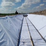
Two huge plastic films are stacked together, and the machine rolls over the edges like a crawler track. What it leaves behind is not a single flat brand, but a peculiar indentation with a width precise to 45 mm. On both sides are two 15 mm wide solid welding strips, forcibly squeezing the middle gap, which is also 15 mm wide, into a miniature hollow channel.
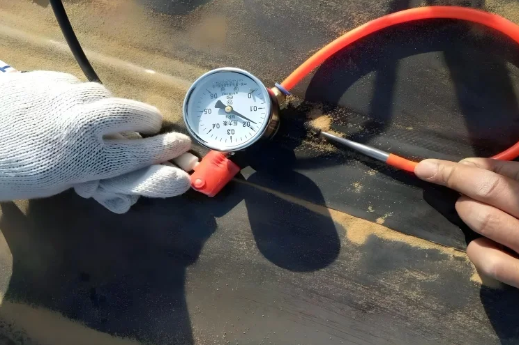
A worker holds a portable hot-melt gun in hand and completely seals one end of this hollow channel, piling up a plastic lump about 3 cm long. At the other end of the channel, an 18-gauge hollow stainless steel probe with a metal tapered tip is poked diagonally into the film at a 45-degree angle. The probe accurately penetrates the outer layer and reaches the inside of that 15 mm wide test line.
The tail of the probe is connected to a 1/4-inch inner diameter transparent polyurethane hose, and the other end of the hose is connected to a miniature air compressor. The motor roars, and 250 kPa of powerful compressed air is poured through the hose into this tiny channel that is up to two hundred meters long. The air valve closes with a bang, completely isolating the outside air.
The inflated plastic channel exposed to the sun will produce tiny thermal expansion and contraction. The tester must hold a stopwatch and wait for a two-minute mandatory temperature stabilization period.
The scale on the dashboard no longer jumps randomly, and a five-minute strict monitoring officially begins. Even the slightest shift on the dial corresponds to extremely rigid engineering rulings:
- The initial gauge pressure reading must be maintained between 200 kPa and 210 kPa
- At an ambient air temperature of 25°C, the maximum allowed natural pressure drop within five minutes is 15 kPa
- If the pressure drop value exceeds 20 kPa, the entire seam area is immediately judged to have a leak point
- The moment the metal probe is pulled out, it must be accompanied by a high-pressure deflation bang exceeding 60 decibels
Hearing that crisp bang, the operator’s hanging heart can finally be set down, as the inside of the entire several-hundred-meter miniature channel is very clear. If the hot wedge welder pauses for even 0.5 seconds while crawling forward, the metal block exceeding 400°C will burn the plastic into a puddle of liquid mush. This mush will flow into the 15 mm hollow channel and solidify into a solid dead end several centimeters long.
When the 250 kPa test gas encounters a dead end, it can only be held back in the first half of the blockage point. The quality inspector pokes a probe at each end of the entire seam; air is pumped at end A, and the pressure gauge needle at end B must rapidly soar to the same reading within 3 seconds. If the readings on both sides do not match, the hidden channel obstruction fault is immediately exposed.
At the moment of heavy machine pressure, a grain of quartz sand with a diameter of only 0.1 mm happens to be stuck between the two layers of film. The high-pressure test gas smells the gap and leaks out. The black needle on the pressure gauge dial will, within just 5 seconds, visibly drop below the 100 kPa scale line.
Finding a leak point on a 150-meter-long line is hard labor. Two construction workers carry 5-liter agricultural spray pots and walk along the 45 mm wide seam belt, spraying as they go. The spray pot is filled with a dish soap aqueous solution strictly mixed at a 1:10 ratio.
The air compressor is turned to the highest gear, desperately pouring 300 kPa of high-pressure gas into the leaking channel. The airflow penetrates the micro-hole pushed out by the quartz sand grain and blows a crystal-clear hemisphere on the surface covered with dish soap solution.
Under visual observation, the soap bubble rapidly expands within 3 to 5 seconds, reaching a diameter of about 5 cm, and pops after reaching the surface tension limit. The inspector squats in the mud and uses a white thick-tip marker to draw a large “X” mark with a side length of 10 cm at the position where the bubble popped.
A handheld extrusion welder, with a tail that constantly sucks in 4 mm solid HDPE welding rods, makes its debut. Its 30 cm long heating barrel maintains a high temperature of 260°C inside. A built-in screw rod forcibly grinds the solid plastic strips into a puddle of scalding fluid.
Maintenance personnel pre-cut a 15 cm diameter round patch of the same material and cover it tightly over the leak point. The black polymer melt is spat out from the gun nozzle, pasting a closed belt with a width of 30 mm and a thickness of about 3 mm along the edge of the patch.
Manual repair relies entirely on the technician’s feel and proficiency to control various operating indicators:
- The output speed of the extrusion gun needs to be maintained at 1.5 kg to 2.5 kg per minute
- The technician’s moving pace must closely match the output speed, with an error not exceeding 10 mm per second
- The Teflon pressure shoe needs to apply a downward manual pressing force of 50 N to the fluid
- The repaired edge belt must exceed the original leak point boundary by a distance of at least 50 mm
Construction Triangle
On the wilderness at 5 AM, the cold is piercing, and the temperature stays at only 8°C. A black high-density polyethylene large membrane, 8 meters wide and 100 meters long, is laid on the muddy ground, its surface covered with dense, cold dew. The operator takes a dry pure cotton large rag and wipes back and forth hard along the 150 mm wide edge seam, completely removing tiny moisture and dust.
The green light on the welder control panel lights up, and the factory default heating block temperature stays at 380°C. The cold, heavy film will greedily swallow the machine’s heat, and the technician reaches out to the right to turn the temperature knob three clicks, forcibly burning the metal block to a high temperature of 410°C. That half-meter-long heavy-duty large wrench clamps the mechanical spring and turns desperately, applying a dead force of up to 1200 N to the 1.5 mm thick film.
The scorching sun at 12 noon turns the entire construction site into a huge oven; an infrared thermometer gun sweeps over the black plastic film surface, and the numbers on the screen soar to 68°C. The operator is drenched in sweat and pushes the walking motor’s acceleration lever, the crawler’s forward pace soaring from 2.0 meters per minute in the morning shift to a high speed of 3.5 meters.
If the fingers are slightly slow and fail to keep up with the rhythm, the 410°C scalding metal block staying on the softened plastic for just 0.3 seconds longer will instantly burn a charred large hole 5 cm in diameter into the material. Doing this kind of delicate work in the field depends entirely on the weather, and the various numbers set on the machine must change at any time according to the sun’s face and the strength of the wind.
| Construction Environment and Film Thickness | Measured Plastic Surface Temperature | Heating Metal Block Temperature | Machine Crawler Crawling Speed | Dead Force Applied by Pressure Roller |
|---|---|---|---|---|
| Early Morning Dew Period (1.5mm) | 10°C – 15°C | 390°C – 420°C | 1.8 – 2.2 m/min | 1200 N – 1400 N |
| Noon Sun Exposure Period (1.5mm) | 60°C – 70°C | 350°C – 370°C | 3.2 – 3.8 m/min | 900 N – 1100 N |
| Strong Wind Drying Period (2.0mm) | 25°C – 30°C | 400°C – 430°C | 1.5 – 1.8 m/min | 1500 N – 1800 N |
A strong wind suddenly blows on the flat construction site, the impeller of the handheld anemometer whirrs, and the screen shows gust speeds reaching 25 km/h. Cold air pours frantically through the tiny gaps between the two layers of film, sweeping away nearly 30% of the heat from the surface of the metal heating block in one breath; the plastic that has just turned into mush contacts the cold wind and instantly forms a hard skin.
Desperately turning up the temperature inside the machine is purely futile; extreme temperatures exceeding 450°C will instantly turn the ceramic heating tubes inside into ashes. To deal with this invisible and untouchable strong wind sabotage, workers can only use the most primitive “clumsy method,” lining up to hold their ground on the muddy earth:
- If the anemometer reading breaks 35 km/h, quickly pull down the main switch to cut off the power
- At 5 meters away on the windward side, pile up an 80 cm high sandbag wall to block the wind
- Bring 50 kg abandoned truck tires to press down the membrane edges firmly every 2 meters
- Push the heated metal block 5 mm deeper into the gap to reduce the cold wind contact area
The thickness of the plastic film itself determines how much capital force the machine needs to expend. For 2.0 mm thick heavy-duty geomembrane, the resistance for heat to penetrate it is more than double that of the 1.0 mm conventional type. For the machine to walk steadily on this hard and thick material, the original smooth soft silicone wheels are all disassembled and thrown into the toolbox.
The technician fishes out hard quenched steel wheels with anti-slip tooth patterns from the box to replace them, and uses a special constant-torque wrench to pull the biting pressure up to 1800 N in one go. The upper and lower layers of stiff thick skin are forcibly kneaded together by this overbearing mechanical force, leaving no room for retreat.
Drizzle falls from the sky without warning; a weak precipitation of less than 1 mm is enough to completely paralyze equipment worth tens of thousands of yuan. Tiny raindrops hit the 400°C metal parts and explode on the spot within 0.01 seconds, turning into scalding high-pressure steam that expands 1700 times in volume.
High-pressure steam with nowhere to escape is smothered tightly in the 45 mm wide semi-molten seam, forcibly pushing apart the plastic molecules that were originally fitted together. When the material has completely cooled down and is cut open to look, the black cross-section is filled with dense hollow bubbles 0.5 mm in size, which break with a hard pull.
- Measured with a handheld portable hygrometer 10 cm above the ground, if it exceeds 80%, it is strictly forbidden to start operations
- Two people carry 2000W industrial heat guns, baking hard 1 meter in front to disperse moisture
- Lay 20 cm wide strong absorbent sponges along the seam to block moisture from the muddy ground
The sky darkens completely, and the temperature drops like a dive at a rate of 5°C per hour. The plastic film that was softened and stretched long by the big sun during the day begins to shrink frantically; a 100-meter-long geomembrane, under the torment of a 40°C day-and-night temperature difference, can forcibly shorten back by nearly 1.5 meters.
This huge pulling force originating from the material itself can pull the seam that hasn’t cooled down and set completely out of shape. After 8 PM, rushing work by the light of floodlights driven by a diesel generator, the machine’s speedometer needle must be held firmly below 1.5 meters per minute, and one must never be greedy for speed.
Letting the crawler turn a bit slower gives the newly melted liquid plastic a precious two-second breathing period to re-bond firmly. As soon as the machine pressure roller rolls over, the auxiliary worker behind must bend down, pick up a 10 kg square solid lead block, and drop it step by step onto the just-pressed seam.
Extrusion Welding
Operating Procedure
Plugging in the 220-volt industrial power cord, the master places the 7.5 kg welder flat on a wooden board. The red numbers on the display jump non-stop, stopping steadily at 275 degrees Celsius. This heat is just enough to simmer the 4 mm thick high-density polyethylene plastic strips into a thick mush.
The hot air nozzle at the front of the machine begins to work accordingly; the thermometer gun hits it showing 290 degrees Celsius. While the machine is still whirring and preheating, a helper nearby picks up a small heat gun and aims it at two 1.5 mm thick black skins to prepare for priming.
The edges of the two black skins overlap, about 75 mm wide. The heat gun nozzle sweeps across with a 3 cm gap, and after blowing for just two seconds, a water-like light appears on the surface of the skin. A palm wearing thick cowhide gloves slaps down, pressing the overlapping area hard.
A round fixing point is made every 30 cm along the entire large seam. The 50-meter-long plastic cloth lies obediently on the ground, without a single undulating wrinkle. The grinder worker bends over and approaches, the 10,000 rpm angle grinder in hand screaming as it touches the edge of the seam.
Replacing with an 80-grit coarse diamond grinding wheel, the originally smooth surface is rubbed into a 30 mm wide grayish-white burr. Not wanting to ruin the base material, the depth of the blade’s entry is held strictly within 0.15 mm. The scraped-out powder flies around, revealing the fresh resin underneath that has never seen air.
The window period left for work is less than 30 minutes, and the two quickly speed up their movements. The master worker pulls a 5 kg bundle of material strips and hangs it on the iron rack by his waist. He pulls out the thread head and stuffs it into the small hole at the back of the fuselage, his finger holding the yellow trigger without letting go.
The alloy screw inside the machine chamber spins rapidly, forcibly rolling the stiff material strips into the 275-degree Celsius high-temperature furnace. After a dozen seconds, the polytetrafluoroethylene base in front of the machine head spits out a puddle of white-smoking soft glue. The master picks up diagonal pliers, snips it off with a click and throws it away, then tilts the machine at a 45-degree angle and presses it down.
- The brass shoe bites hard into the lower material surface and moves forward
- The V-shaped small groove at the front tightly clamps the upper edge
- The 290-degree Celsius hot air blows desperately at the place 5 cm ahead
- The melted soft glue emerges at a rate of 1.8 kg per minute
The trigger is pressed to the bottom, the sound of the motor becomes muffled, and the hot-to-the-touch soft glue, like toothpaste, keeps gushing out from the base gap. The muscles of both arms are all tensed, and the wrists have to exert a dead force of 5 kg downward.
The master moves back with small steps, his eyes staring unblinkingly at the black glue strip squeezed out from behind the base plate. The backward pace is set at 1.2 cm per second, not daring to have the slightest tremble. A 35 mm wide black bulge with a thickness of 3.5 mm in the middle slowly takes shape.
When encountering a place where a drain pipe protrudes, the work changes. The master quickly switches to a half-moon shaped nozzle to deal with the corners of the pipe edge.
- The pipe base and the laid large surface form a 90-degree right angle
- The gesture of holding the machine changes from pressing down to pushing forward at an angle
- The weld bead circles tightly against the outer skin of the 110 mm diameter hard plastic pipe
- The machine creates a standard circular ring with a diameter of 150 mm
- Every 10 cm forward, it must stop for 1 second to scrape off the excess glue
Ending and breaking the line is a pure craft job. Seeing that there are 2 mm left to the end, the finger immediately releases the trigger to stop the motor from feeding material. The master suddenly lifts the machine head up, pulling out a long black fine thread in mid-air.
The apprentice nearby, holding a half-moon shaped steel knife, cuts the fine thread at the root in one stroke before it hardens. Another helper, clutching a wide-mouthed metal scraper, manages to flatten the excess scalding large lump at the end before the glue cools down, scraping it to the same 3.5 mm thickness as the front.
If a long-shaped hole is dug in the ground, the repairer will use large scissors to cut an oval-shaped piece of material 400 mm long and 300 mm wide to cover it. The person grinding circles outward along the edge of this piece of material, scraping out a rough belt.
- The center of the oval piece aligns perfectly with the hole underneath
- The heat gun points once in each of the four directions—east, south, west, and north—to fix it
- The angle grinder draws a large circle along the edge
- The scraped burr exceeds the planned line edge by 5 mm
The master carrying the hot machine bends down and circles the oval piece on the ground exactly once. The squeezed-out soft glue overlaps at the place where it just started; the master doesn’t release the strength in his hand, letting the machine head continue forward for 20 mm.
These extra 20 mm thickly cover the old material. The apprentice lifts the scraper and quickly levels and spreads the bulging area. A circle of undulating sealing strips firmly seals the original hole to the base material.
Construction Classification
At the bottom of a 100,000 square meter landfill trench, black waterproof large material is laid as far as the eye can see. A hard plastic pipe with an outer diameter of 600 mm pokes straight out of the ground, blocking the path of the entire large surface’s expansion. Two workers in yellow reflective vests approach the pipe and pull out a 5-meter-long steel tape measure. They measure it; the circumference of this round pipe is exactly 1884 mm.
The assistant nearby uses wide-mouthed scissors to tear off a piece of 2.0 mm thick flat black material from a roll of stock weighing up to 200 kg. With both hands pulling hard, he forcibly rolls it into a hollow thick cylinder 450 mm high. He fits the cylinder into the pipe, and the lower half is folded outward, like a flattened large skirt edge.
This folded-out skirt edge overlaps with the waterproof cloth underneath by about 150 mm in width. A small heat gun weighing about 1.2 kg is brought up, and it roasts back and forth along this circle of overlapping black edges for about 5 seconds. The originally shriveled material surface glints with a moist light, and the two layers of material stick together limply.
- The long-shaped nozzle in front of the machine is replaced with a 45-degree angled brass elbow.
- Following the circle at the bottom of the sleeve, a 35 mm wide scalding glue tape is firmly squeezed out.
- For every 100 mm the machine head advances, it must forcibly pause for 0.5 seconds against the hard pipe wall.
- The very top of the sleeve is tightened with two circles of 15 mm wide stainless steel clamps, and the gap is filled with black glue.
Walking 50 meters south along the pipe, two 100 mm wide machine seams on the ground happen to collide. A large machine with two iron rollers cannot turn at such a narrow intersection, leaving a tiny crack about 20 mm long on the spot. A worker carrying a large pair of long-handled scissors steps forward, snipping out a thin round piece 150 mm in diameter.
When the number on the pressure gauge really reaches 30 kPa, a water column will drill into the soil through this crack, which is no bigger than a needle’s eye. That black thin round piece is unbiased, exactly covering this 20 mm long exposed crack perfectly. The person nearby is quick-handed, using a small heat gun to quickly make 6 soybean-sized fixing points on the edge of the round piece.
The grinding wheel rubs desperately around the outer ring of the round piece, accompanied by piercing noise, scraping out a grayish-white path a full 40 mm wide. The 7.5 kg machine is pressed down, and following the grayish-white path, it forcibly creates a seamless closed black circle.
Walking another kilometer outward to the clearing where the work has just been inspected, a dozen or so long-shaped large holes are scattered in front of the eyes. Half an hour ago, the quality inspector took a sharp utility knife and cut away a piece of material 1 meter long and 0.3 meters wide to send to the lab for a tensile test. The whistling wind pours through the opening.
The person nearby quickly takes a newly cut rectangular piece of material to cover it. Every edge of the new material must be at least 150 mm wider than the original opening. The four sharp right-angled corners are all trimmed into smooth arcs with a 50 mm radius by large scissors. The grinder spins rapidly three times along the rounded corners, leaving no angular places.
| Repair Area Classification | Size of Material Covered | Width Pressed onto Original Cloth | Distance the Machine Crawls per Minute |
|---|---|---|---|
| Where large pipes emerge from the ground | Total height exceeds 450 mm | 150 mm | 0.4 m |
| Where two large seams intersect in a cross | 150 mm diameter round material | Measurement not needed for this item | 0.6 m |
| Large long holes left by cutting samples | Length and width exceed the original opening by 300 mm | 150 mm | 0.8 m |
| Recessed dead corner positions with sharp angles at the bottom of the pit | Cut on-site based on folding conditions | 100 mm | 0.3 m |
At the southwest corner of the site, a large catchment pit 3 meters deep has been dug, with four walls being yellow earth steep slopes slanting down at 75 degrees. The waterproof cloth laid at the bottom is forcibly pressed into the pit, resulting in four sharp right-angled dead nests at the very bottom. The stiff corners simply do not obey, tilting up about 5 cm high.
A man wearing a safety belt carries the hot machine on his right shoulder, his hand firmly clutching a 25 mm thick large anti-slip hemp rope. The other end of the hemp rope is tied to the crawler of that 5-ton excavator above. The place for his feet is covered with loose coarse sand; the slope is too steep, and it takes effort for both legs even to stand straight.
He simply kneels on one knee in the sand pit at the bottom of the slope, holding the still-whirring machine in both hands, aiming firmly at the innermost thin seam. Soft material at high temperature over 250 degrees is forcibly stuffed into the corner.
- The brass machine head stands up, plunging into the deepest nest where the three sides meet at an 80-degree tilt angle.
- The white-smoking soft material fills the corner accordingly; this one point alone has more than 120 grams squeezed in.
- This person’s left arm presses hard against the earth slope behind, holding the machine for 15 seconds without daring to shake.
- Once the heat dissipates, this black glue lump reaches an amazing thickness of 12 mm.
Quality Testing
Non-Destructive Testing
Workers handle thick seams with a thickness exceeding 2.0 mm. They will squeeze a 10 mm wide transparent gel liquid onto the black plastic edge. Holding a matchbox-sized probe in hand, they slide it over. The probe emits 50 MHz high-frequency sound waves into the hard plastic, relying on echoes to understand the internal physical structure.
A green broken line jumps on the display screen. Even if a tiny bubble 0.1 mm wide is hidden inside the plastic, the green line will instantly soar, breaking the 40% scale line on the screen. The hand holding the probe cannot move too fast; the moving speed is strictly limited to within 15 cm per second; if it moves too fast, the sound waves will miss extremely tiny gaps.
Before starting work, the operator takes out a heavy steel block with a polished shining surface. Small holes 1.5 mm and 2.0 mm deep have been pre-drilled into the steel block with a metal drill bit for the sonic instrument to find the scale.
- The running speed of sound in plastic is locked at 2350 meters per second
- The probe emits 1000 dense knocking sound waves per second
- The filter for receiving noise is set at the 10 to 75 MHz frequency band
- The circular sounding piece touching the gel has a physical diameter of only 6.35 mm
Sound waves cannot penetrate special double-line seams with a hollow tube in the middle. Workers bring in a large 5-horsepower air compressor. A 30-meter-long black thick-walled rubber hose is laid out on the ground, the entire roll weighing 15 kg. The end of the hose is connected to a nozzle made of pure copper, the diameter of the air outlet hole being only 4.8 mm.
The gauge needle on the air compressor tank stays steadily at the high-pressure scale of 50 psi. A worker holds the metal air nozzle in one hand, suspended 50 mm above the overlapping edge of the two layers of plastic. High-pressure cold air slices vertically toward the seam like a knife. Another worker lies prone on the black plastic surface heated by the sun, his eyes staring at the stressed edge.
Huge wind pressure causes the unbonded plastic thin edges to vibrate violently. In places with a 3 mm wide gap, the high-pressure air slams in, carrying dust and spraying in reverse from the other end onto the prone worker’s fingers. The person holding the air gun walks along the seam, controlling the speed at 10 meters per minute. If the steps are too fast, the eyes simply cannot catch the brief vibration frames.
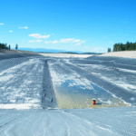
After the site covering tens of thousands of square meters is paved with black geomembrane material, a truck filled with 1000 liters of clean water drives slowly along the top of the slope. Dozens of small nozzles at the rear, 50 cm apart, evenly spray water mixed with salt downward. 600 to 800 liters of water are poured per hectare of plastic surface to ensure the large area is wet enough.
The tester puts on an 8 kg high-capacity battery pack. A 1.2-meter-long pure copper conductive rod is pushed hard into the moist mud at the periphery of the plastic zone. The tester holds a 1.5-meter-wide brass brush with both hands; the bristles look like an extra-large broom, and the tail is connected to the battery on his back with a thick cable.
A continuous high voltage of 200 to 400 volts pours through the cable into the moist brass bristles. The tester drags the brush back and forth over the wet plastic surface. The dashboard at his waist shows the voltage maintained at 300 volts, while the ammeter needle lies dead at the 0 mA position. The insulating geomembrane material completely blocks the current outside.
| Leak Detection Equipment Appearance | Corresponding Plastic Film Thickness | Worker’s Walking Speed | Machine Detected Hole Size |
|---|---|---|---|
| Thickness measuring sonic slider | Thickness above 2.0 mm | Up to 15 cm per second | 0.1 mm tiny air pore |
| Pure copper high-pressure air gun | 1.0 to 1.5 mm | Up to 10 meters per minute | 3.0 mm unbonded seam |
| Wide-span energized copper brush | All sizes and thicknesses | Maintained at 30 meters per minute | 1.0 mm water-permeable hole |
The brass bristles sweep over a tiny pinhole only 1 mm wide. The saltwater on the surface leaks through this small hole into the muck below. The high-voltage current instantly finds a straight path to the mud. The ammeter needle at the waist jumps suddenly, leaping past the 15 mA red warning line.
A small speaker on the battery pack erupts in a 90-decibel piercing scream. A sharp howl comes through the soundproof headphones the tester is wearing. He stops immediately, takes out a white thick-tip marker, and draws a large cross on the pinhole that is constantly bubbling tiny water bubbles on the ground.
The long brush is pulled off and replaced with a small point-like metal probe, which probes back and forth at the place where the cross was drawn. The originally 1.5-meter-wide search range is forcibly narrowed down to a circle 5 cm wide. The recorder hanging on his chest automatically writes the GPS latitude and longitude coordinates of this hole into a plain text data file.
Heavy dump trucks dump 60 cm thick river bottom gravel onto the laid plastic film. Dragging a brush over sharp rocks won’t find a leak at all. On the eve of laying the geomembrane, workers pre-bury a large piece of stainless steel wire mesh in the bottom soil. The distance between each wire is measured with a tape measure, snapped at exactly 3 meters.
Moisture in the soil is responsible for conducting weak electrical signals; the moisture content tester shows soil humidity exceeding 10%. The knob on the battery pack is turned to the maximum extreme 600 volts. The tester holds two thin metal rods wrapped in thick rubber in his hands; the two rods are held apart by a plastic hard tube in the middle, with the physical gap locked at 1 meter wide.
- A portable receiving box captures weak potential fluctuations of 0.1 mV
- The metal probe tips are forced through the gravel heap to a depth of 10 cm
- The waist-mounted data collector writes a new record into memory every 3 seconds
- Small reading fluctuations below 5 mV are deleted by the computer as wind noise
The worker walks in a straight line over the stones, poking the two metal rods into the gaps between the stones to collect a signal every 1.5 meters. The millivolt number on the handheld LCD screen has been at an extremely low state. Walking next to a pile of gravel that looks completely normal, the number jumps from 2 mV to an extremely high point of 85 mV.
The leaking current draws invisible concentric circles in the moist bottom mud. The tester approaches in the direction where the reading gets higher and higher, and inserts a red plastic triangular flag at the top of the stone pile. A crawler excavator enters the site and carefully digs away 1.5 tons of sharp gravel. A 4 cm long mechanical tear is exposed underneath.
Destructive Testing
After a worker walks a 150-meter-long black geomembrane seam, he uses a knife to cut a rectangular piece of rubber 900 mm long and 300 mm wide from the hot seam. A slightly larger spare piece of rubber is covered over the edge of the large hole left after cutting, and a hot-melt gun sprays 200°C high-temperature plastic paste to seal the surroundings tightly. The numbered original rubber is packed into a kraft paper bag and sent to the laboratory where the temperature is always set at 23°C.
A technician operates a press with a hydraulic rod to forcibly press 10 thin strips out of the rectangular rubber, with the width locked at 25 mm. The tool is extremely sharp; leaving a 0.1 mm plastic thorn on the edge would ruin the subsequent stress test. The strips are divided into two halves: 5 are used to test the force required to tear the two layers of rubber apart, and the remaining 5 are used to calculate horizontal tug-of-war strength.
At 6 AM, the tensile machine is powered on to warm up for 15 minutes, and a standard iron weight weighing 50.0 lbs is hung under the jaw. The numbers on the screen flash slightly between 49.9 and 50.1 lbs. A caliper is stuffed into the middle of the upper and lower iron jaws to confirm that the zeroed machine gap stops exactly at 50 mm.
The machine’s two iron jaws open, firmly biting both ends of the 25 mm wide strip, applying a biting force of 80 lbs to prevent slipping midway. The length of the strip suspended between the two jaws is set at 50 mm. A dial on the side of the machine turns, and the upward pulling speed is locked at 50 mm per minute.
One end of the two layers of bonded rubber is forcibly peeled open and stuffed into the upper and lower iron jaws respectively. The machine starts and pulls upward at a constant speed of 50 mm/min, and the 1.5 mm thick interface suffers violent tearing in the vertical direction. The tensile number on the electronic screen soars from 0 past the 60 lbs scale line.
- The breaking position must occur on the rubber’s own material
- The bottom line for passing the forced pull is set at 91 lbs/inch
- The torn range at the seam interface is controlled within 25%
- The computer writes 10 tensile numbers into the hard disk every second
- The passing threshold for the 5 thin strips is rigidly set at 80%
Replacing with a strip for testing horizontal tension, the overlapping area of the two layers of rubber stays in the suspended space between the upper and lower jaws. The tensile machine mimics the soil sinking, pulling the rubber hard toward both ends. The jaw keeps rising, and the 25 mm wide area under stress undergoes severe contraction deformation. A layer of white patterns is pulled onto the surface of the rubber, and as the numbers pass 120 lbs, signs of elongation appear instantly.
- Horizontal tug-of-war test tensile reading crosses 120 lbs/inch
- The rubber is stretched by more than 50% of its original length and deforms
- The extreme value of the total stretched length of the rubber before completely snapping reaches 700%
- The fracture of the forced break shows an irregular serrated tear
| Violent Tearing Item | Machine Clamping Posture | Tearing Moving Speed | Passing Tensile Value | Machine Inspection Target |
|---|---|---|---|---|
| Vertical Peel Method | Upper and lower layers clamped separately | 50 mm per minute | Break through 91 lbs/inch | Bonding surface heating temperature |
| Horizontal Pull Method | Both ends clamped flat and firm | 50 mm per minute | Break through 120 lbs/inch | Roller squeezing pressure force |
Looking at the fracture edges of the shredded residue under a strong light, a large area of white plastic filaments appears, and the originally bonded seam still sticks together firmly. The tensile machine forcibly tore the 1.5 mm thick intact rubber but failed to tear that 15 mm wide weld. A blue pass stamp is stamped on the record board.
One strip made a crisp sound when the tension reached 85 lbs, and the two layers of rubber that were supposed to be stuck together split smoothly from the middle like peeling a sticker. The wave graph on the electronic screen dropped to the bottom like a waterfall within a few milliseconds. The technician took out a red pen and drew a large cross on this set of strips.
This set of scrapped data implicates a 150-meter-long seam. Workers retreat 3 meters to the left and 3 meters to the right from the position where the hole was just cut. The blade cuts two new 300 mm wide pieces of rubber to send to the lab. As long as one of the two newly sent samples fails to hold above the 91 lbs baseline on the machine, the entire 150-meter-long seam is scrapped.
A brand new black rubber repair strip 150 mm wide is laid over the scrapped seam. The hot-melt gun re-applies two passes along the left and right sides of the new patch. Scalding plastic liquid exceeding 200°C seals this area tightly. The newly repaired area quietly waits for the next time to be cut open and taken for pulling.
The rectangular sample that successfully passes is cut in half; the remaining 450 mm is stuffed into a moisture-proof plastic bag along with the lab report. A waterproof sticker printed with GPS latitude and longitude, the date of work, and the worker ID is pasted on the surface of the bag. Thousands of paper bags are neatly coded and stored for 5 years in a large iron cabinet where the temperature is year-round set at 20°C.