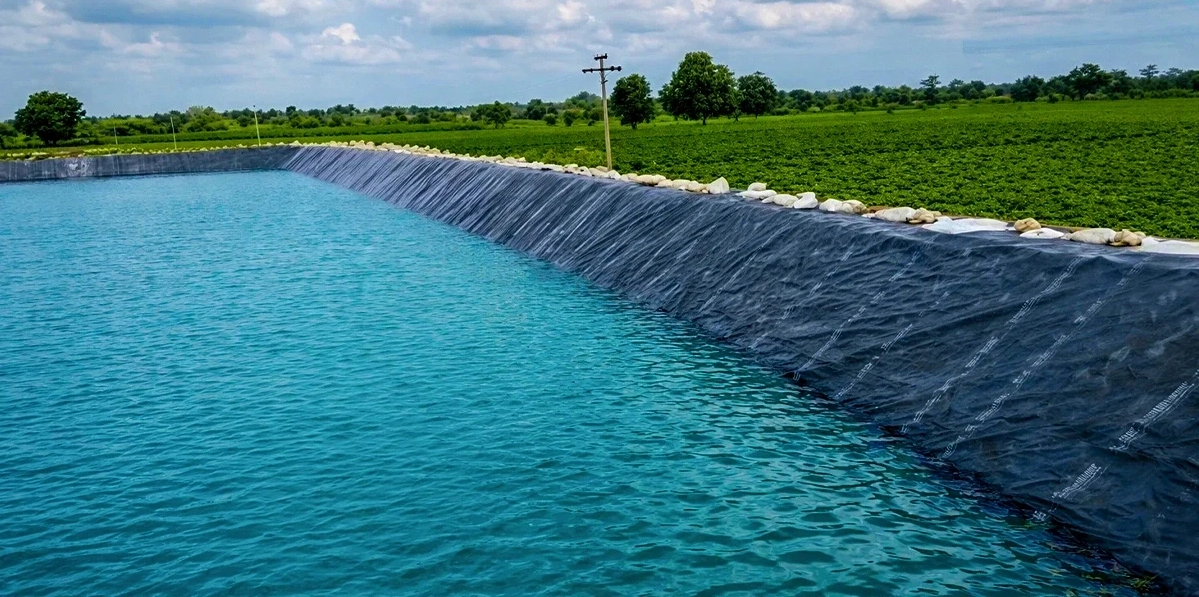
Select HDPE geomembrane 0.5–1.5mm, with anti-UV lifespan of 10–20 years; can reduce evaporation by 30%–50%. Construction requires compacting the base soil + hot-melt welding, with joint strength ≥90% for more stable seepage prevention.
UV Resistance
Standard for Additives
Ultraviolet rays in the 290nm to 400nm band of the solar spectrum carry 300 to 450 kJ/mol of photon energy. This energy intensity exceeds the Carbon-Carbon (C-C) bond binding force with an energy level of 347 kJ/mol in polyethylene molecules. Photon impact will trigger polymer chain breakage, producing highly reactive free radicals and inducing chain oxidation reactions.
Industrial-grade HDPE liners are mixed with 2.0% to 3.0% mass concentration of carbon black as a physical barrier during the production stage. According to ASTM D1603 standard testing, this proportion of carbon black can absorb and convert more than 99% of incident UV energy. The carbon black particle size must be strictly controlled between 20nm and 25nm to ensure the formation of a dense protective layer within the polymer matrix.
ASTM D5596 microscopic evaluation requires carbon black dispersion to reach Category 1 level, meaning that at 100x magnification, no agglomerated particles exceeding 10 microns are observed. Uneven dispersion leaves physical loopholes, leading to localized polyethylene chains showing microscopic embrittlement points within 24 months. These weaknesses evolve into macroscopic cracks under water pressure load, shortening the service cycle of the anti-seepage system.
- Carbon black content standard value: 2.0% – 3.0% (ASTM D4218)
- Carbon black particle size specification: 22nm ± 3nm
- Microscopic dispersion grade: Category 1 (ASTM D5596)
- Carbon black recovered ash content: less than 0.1% mass ratio
- UV absorption rate: > 99.5% energy capture
In addition to physical barriers, high-performance materials also add Hindered Amine Light Stabilizers (HALS) to clear free radicals generated during the oxidation process. Oxidative Induction Time (OIT) is a quantitative indicator for evaluating this chemical protection capability. In the ASTM D3895 200°C high-temperature pure oxygen test, standard liners are required to maintain 100 minutes without degradation reactions.
For strong UV regions with annual radiation exceeding 160 kLy/y (Langley), high-pressure OIT testing (ASTM D5885) is more effective. Under a 3.4 MPa pressure environment, the liner needs to reach more than 400 minutes of stability. Data shows that materials containing high-performance stabilizers still maintain an antioxidant retention rate of over 80% after 1600 hours of exposure.
- Standard OIT initial value: > 100 minutes (ASTM D3895)
- High-pressure OIT initial value: > 400 minutes (ASTM D5885)
- HPOIT retention rate after 1600h UV exposure: > 80%
- OIT retention rate after 90 days in 90°C oven aging: > 55%
- Density index: resin base material above 0.940 g/cm³ level
Material degradation caused by UV rays usually occurs within a depth of 0.1mm to 0.2mm on the surface. Increasing liner thickness provides a physical layer of protection margin; 1.5mm HDPE has higher fault tolerance than 0.75mm specifications. Even if surface molecules undergo slight embrittlement after 20 years, the deep 1.3mm structure can still maintain a tensile strength of 24MPa.
Polyolefin liners without optimization usually see elongation at break drop from over 700% to below 100% after 18 months of field exposure. Industrial-grade products complying with the GRI-GM13 standard maintain a mechanical strength retention rate of over 90% after accelerated aging experiments. This performance span directly relates to the structural safety and maintenance frequency of the reservoir in the following decades.
According to the ASTM D5397 Single Edge Notch Constant Tensile Load (NCTL) test, materials with strong UV resistance have higher Environmental Stress Crack Resistance. The standard requires the material to persist for 500 hours without breaking under constant load. Free radicals generated by UV radiation erode the amorphous regions of the polymer chains, reducing this crack resistance life, so the quality of additives is crucial.
- Tensile yield strength: maintain above 15 kN/m (1.0mm specification)
- Elongation at break: original value > 700%
- Tear resistance strength: > 120 N (ASTM D1004)
- Puncture resistance strength: > 320 N (ASTM D4833)
Comparison of Different Materials
The atomic arrangement inside HDPE is very compact, with crystallinity usually falling in the 60% to 80% range. This dense molecular matrix blocks UV photons from penetrating into deep layers, controlling photochemical damage within a surface thickness of 0.05mm. The crystallinity of LLDPE is maintained at 30% to 40%; although it feels softer during installation, the damage depth produced by photons hitting molecular chains often reaches 1.5 times that of HDPE.
| Material Type | Density (g/cm³) | Crystallinity Percentage | UV Absorption Rate | Expected Exposure Life |
|---|---|---|---|---|
| HDPE | 0.941 – 0.960 | 60% – 80% | 99.5% (with carbon black) | 30 – 50 years |
| LLDPE | 0.919 – 0.925 | 30% – 40% | 99.2% (with carbon black) | 20 – 30 years |
| EPDM | 0.860 – 0.870 | Amorphous structure | 99.8% (Intrinsic property) | Above 50 years |
| PVC | 1.30 – 1.45 | Below 10% | 85.0% (Fast decay) | 7 – 10 years |
The C-Cl bond binding energy in PVC membranes is only 338 kJ/mol. Under 254nm short-wave UV radiation, chlorine atoms easily detach from the molecular chain, causing the material to turn yellow and rapidly lose elasticity. EPDM rubber relies on a saturated Carbon-Carbon bond skeleton; under high-intensity radiation of 160 kLy per square centimeter, it can still keep tensile elongation at an original level of about 95%.
- HDPE material strength retention ratio exceeds 90% after 1600 hours in ASTM D7238 experiments
- EPDM membranes exposed to 100 pphm ozone for 100 hours show no microscopic cracks observed on the surface
- After 20 years of service for a 1.5mm specification liner, the OIT at 1.0mm depth is still 200 minutes
- The migration speed of plasticizers in PVC liners under heat increases by 3 to 5 times under UV light
The degradation speed triggered by UV rays follows the law of the Arrhenius equation. For every 10°C rise in ambient temperature, the speed of chemical destruction doubles. Dark liners under direct sunlight can see surface temperatures soar to 70°C. In poorly formulated materials at this temperature, internal stabilizers will evaporate completely within 5 years, leading the membrane to enter an embrittlement period and show leakage.
Annual UV radiation in high-altitude areas exceeds 200 kLy year-round. HDPE liners with a thickness of 2.0mm combat an annual surface degradation loss of about 5 microns by increasing physical redundancy. Measured data shows that thick specification materials have a burst pressure drop of only 12% after 20 years, while thin specification materials lose over 45% of performance in the same environment.
Tertiary carbon atoms on the main chain of Polypropylene (PP) type materials are very sensitive to light; unmodified PP will turn into powder within just a few months under UV light. Agriculture-specific fPP, by changing molecular chain regularity, reaches UV resistance levels close to HDPE while possessing 800% elongation. This material can withstand stress extrusion better than ordinary materials in reservoirs with complex terrain.
- Each 1% increase in carbon black concentration can cause UV transmittance to drop by about 30%
- HDPE yield strength in exposed environments is usually stable in the 15-18 MPa range
- P-type carbon black can achieve Category 1 grade microscopic distribution, eliminating weak zones over 10 microns
- Formulas containing hindered amine stabilizers have higher performance retention in 90°C aging tests
- When carbon black particle size is near 22nm, the scattering efficiency for 300nm band UV rays is highest
Initial HPOIT values for high-quality HDPE liners are usually higher than 500 minutes. Stored in a 90°C oxygen experimental box for 90 days, this value can still remain above 400 minutes. This chemical redundancy ensures the anti-seepage layer can handle over 30 years of field exposure. EPDM, with its intrinsic molecular chain stability, consistently occupies a top industry position in fatigue resistance and weatherability.
The color performance of the material does not determine endurance; the distribution quality of carbon black is the physical foundation. P-type carbon black has lower ash content than ordinary carbon black. in ASTM D5596 microscopic rating, this type of carbon black can reach Category 1 uniformity. Consequently, no unprotected loopholes with a diameter exceeding 10 microns exist on the polymer surface, preventing stress cracking in high salinity/alkalinity and strong sunlight environments.
According to the ASTM D5397 notch tensile test, high-quality materials can persist for 500 hours without breaking under constant load. Any product below 300 hours will produce large-area leakage points within 5 years under the combined action of water pressure and light. Requiring yield elongation above 12% and elongation at break over 700% is the physical safeguard to avoid premature system failure.
- Tensile yield strength of 1.0mm HDPE liner needs to reach 15 kN/m
- Degradation caused by UV rays is mainly concentrated at a depth of 0.1mm to 0.25mm on the surface
- High-quality liners still have 700% elongation at break after 1600 hours of accelerated aging
- Materials with plasticizer content exceeding 30% will have a 5% volume shrinkage under UV light
Improving Lifespan
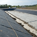
The soil hardness at the bottom of the reservoir is directly related to whether the geomembrane can serve smoothly. Before construction, a road roller must be used to treat the base soil in layers to ensure soil density reaches over 95%. If stones or tree roots with a diameter greater than 5mm exist in the soil layer, they must be thoroughly cleaned. Under 1.0MPa water pressure, these sharp objects will become stress points, causing micron-level depressions or even perforations in the HDPE membrane.
Laying a layer of 300g/m² to 600g/m² geotextile under the geomembrane can provide a cushioning effect. This practice disperses the originally concentrated pressure over a larger contact surface, keeping the membrane deformation rate within a safe range of 5%. Experimental data shows that with this underlay, the puncture resistance of the anti-seepage system usually increases by 40% to 60%.
Welding quality is the physical bottleneck determining reservoir lifespan. When using dual-track extrusion welding, the overlap width of two membranes should be maintained between 100mm and 120mm. Construction performance is most stable when the air temperature is between 10°C and 40°C. The welder pressure is set between 500N and 1000N to ensure two 10mm wide flat marks are left at the weld seam.
- Welder walking speed controlled at 2.0 – 3.0 m/min
- Weld seam air pressure test needs to maintain 250kPa pressure for 5 minutes
- Pressure drop must be lower than 10% to be considered qualified
- Random sample cutting for tensile experiments; strength retention rate must exceed 90%
- Dead corners such as T-joints use -30kPa vacuum hood check
Anchorage trench dimensions are usually set at 50cm wide and 50cm deep. This is the physical basis for ensuring the membrane does not slide down under the heavy pressure of high water levels. Fine sandy soil should be used for backfilling, with a dry density after compaction of no less than 1.6 g/cm³. For large projects with slopes exceeding 1:3, the pull-out force calculation for anchorage points needs to be designed with a 1.5x safety margin.
Covering the geomembrane with a 30cm thick soil layer or gravel can block direct UV radiation. This keeps the surface temperature of the membrane stable at around 25°C, avoiding rapid consumption of additives caused by high temperatures. In areas with frequent water level fluctuations, installing 15cm thick concrete prefabricated blocks can effectively resist scouring from flow velocities above 2m/s.
- Exposed parts above the water line inspected every 6 months
- Monitor HPOIT values to understand the consumption progress of antioxidants
- Manual cleaning should be started when silt thickness exceeds 20cm
- Repair patches for damaged areas must exceed the hole edge by 150mm
- Bubbles with a diameter greater than 30cm need to be cut for air venting and secondary heat welding
The pH value of agricultural water will affect the service status of the material. HDPE is chemically very stable in water bodies with pH values from 2.0 to 13.0. If the water oxygen content is too high, it will accelerate the loss of surface antioxidants. Maintaining water depth above 2 meters and using the specific heat capacity of water to regulate membrane surface temperature can significantly reduce the speed of thermal-oxidative degradation.
The slope of the reservoir is the area with the most complex stress. The membrane here is under dual pressure of long-term dry-wet alternating and sunlight exposure; additive consumption speed is 3 to 5 times faster than the pool bottom. Covering an extra layer of 1.0mm geomembrane as a sacrificial layer on the slope can protect the main membrane from environmental stress damage, extending the expected life of the overall system by more than 10 years.
Notched tensile testing according to ASTM D5397 specifications shows that high-quality materials can persist for 500 hours without cracking under constant load. Any inferior product below 300 hours will produce large-area leakage points within 5 years under the combined action of water pressure and light. Therefore, requiring yield elongation above 12% and elongation at break over 700% is mandatory during material selection.
Connections at inlet and outlet pipes are frequent leakage points. Use HDPE flanges with stainless steel bolts, padded with 3mm thick EPDM rubber gaskets. Tightening torque should reach between 40 Nm and 60 Nm. This connection method can withstand frequent water flow impact and prevent physical loosening during thermal expansion and contraction processes.
- Membrane thickness around the inlet is suggested to increase to 2.0mm
- Flange bolt hole error must be controlled within 1.5mm
- Weld width of wall-penetrating pipes shall not be less than 30mm
- 24-hour full water static pressure monitoring required after completion
Evaporation Control
Mainstream Solutions
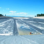
At summer noon, every square meter of open water surface receives about 1000W of solar radiation. This energy makes water molecules extremely active, jumping out of the water surface into the air like countless tiny springs. Adopting 1.5mm thick Reinforced Polyethylene (RPE) floating membrane, which has dense polyester fibers woven inside, makes its tensile strength exceed 200N. Spreading it on the water surface is like putting a light-tight “raincoat” on the pond, directly suppressing an annual 2000mm evaporation depth to below 100mm.
Installing such large-area plastic membranes cannot rely on glue, but uses an automatic crawling welding machine like a small car. It travels at a speed of 2 to 3 meters per minute along the joints, melting two membranes together via high temperature. To ensure no air leaks, the welder will charge 150kPa of air between dual weld seams and observe for 5 minutes. At the reservoir shore, membrane edges are tucked into a soil trench 500mm wide and 600mm deep, pressed with 20cm thick gravel. Even if a strong wind of 120km/h blows outside, the membrane will not be lifted.
| Technical Solution | Common Material Specification | Percentage of Evaporation Blocked | Water Saved per Hectare over 10 Years |
|---|---|---|---|
| Fully Enclosed Floating Membrane | 1.5mm High Density Polyethylene | 98% | 190,000 cubic meters |
| Floating Hexagonal Blocks | 250mm Polyethylene Modules | 89% | 165,000 cubic meters |
| Suspended Shade Net | 320g/m² Knitted Net | 45% | 88,000 cubic meters |
| Hollow Pressure Balls | 100mm Diameter HDPE | 91% | 170,000 cubic meters |
These hollow floating balls, called “bird balls,” usually have a diameter around 100mm. 116 units are placed per square meter on the water surface. To prevent balls from being blown away by wind, the factory fills the balls with 30% water as ballast, so the ball’s center of gravity is firmly rooted in the water. Even if wind speed reaches 15m/s, these balls will only squeeze together neatly instead of stacking or drifting ashore. 5% carbon black is added to the ball plastic, ensuring that after 10 years of exposure to harsh sun, the degree of material embrittlement will not exceed 20%.
Hexagonal modules use an edge-to-edge interlocking design. Each module weighs between 250g and 400g. When they automatically line up on the water surface, they can block more than 85% of sunlight. Without light, algae in the water cannot perform photosynthesis; chlorophyll content in the water can usually be controlled at a level as low as 10μg/L. If your reservoir’s water level fluctuates more than 0.5m daily, using these small floating bricks is safer than using a whole large membrane, as it won’t produce dead folds because the water level drops too fast.
In some huge lakes where neither racks can be built nor membranes laid, an invisible agent must be used. This chemical is called cetyl alcohol; sprayed on the water surface by automatic machines, it spreads into a molecular film only 0.002 microns thick. Only 50g of agent is needed per hectare per day. However, this film is very delicate; as long as wind speed exceeds 3.5m/s, the film will crack. Therefore, this solution needs re-spraying every 24 to 48 hours.
- Heat Reflection: Applying a silver coating to the cover membrane can bounce 65% of sunlight directly back.
- Margin Reservation: When laying the membrane, leave 5% to 8% extra slackness to prevent the membrane from snapping after water dries up.
- Drainage Design: It’s best to place a small pump with a 10L/s flow every 20m on the membrane surface to avoid rainwater accumulating on top and collapsing the system.
The shade net system stretches steel cables with spans up to 50 meters above the water surface. Net weight is generally chosen at 320g/m². Although it cannot completely block air flow, it can block 75% of heat radiation. Measured data shows that water temperature under the shade net is 4°C to 6°C lower than water under direct sun. Because of this few degrees difference, the vapor pressure above the water surface can drop by about 30%.
In arid regions where every cubic meter of water is worth more than $2, the money for this equipment only accounts for 15% of the saved water cost. If fertilizer concentration in your reservoir is very high, then Teflon (PTFE) coated materials must be used. Working in water with pH values from 3 to 11 for 20 years, the loss of strength (mechanical strength) does not exceed 5%. This is like putting anti-corrosion armor on the reservoir; no matter what chemicals are added to the water, it won’t rot.
Gas management under the membrane is also very important. A 200mm diameter pressure relief valve should be installed every 500 square meters. If silt at the bottom ferments to produce methane, bubbles will lift the membrane like a large balloon. Once the membrane is stretched by more than 12%, the plastic will undergo permanent deformation, even pulling open the edge seals. Therefore, ensuring clear gas paths is as important as ensuring no water leaks.
If the water is mixed with herbicides, ordinary polyethylene membranes might swell like a sponge. In this case, switching to reinforced polypropylene (fPP) is more appropriate. The dimensional change of this material after contacting chemicals is less than 1%. Choosing the right material can turn a job that originally required quarterly inspections into a once-a-year visit.
Liner Materials
Most black liners laid at the bottom of open reservoirs contain 2% to 3% carbon black; the albedo of this material is only 0.05. Under harsh sun, the liner absorbs over 90% of solar radiation. Heat passes through the anti-seepage membrane with a thermal conductivity of 0.45-0.52 W/(m·K), raising the bottom water temperature to 35°C to 45°C. Warm water density decreases and floats upward, forming never-ending thermal convection within the pool, continuously delivering heat energy to the water surface.
This bottom heating mechanism causes the surface saturated vapor pressure to rise rapidly. In a typical climate with ambient temperature 30°C and humidity 40%, for every 5°C rise in water temperature, the pressure of water molecules escaping into the air increases by about 25%. To break this process, a white LLDPE membrane with added titanium dioxide must be covered on the water surface. The albedo of the white surface exceeds 0.80, reflecting most of the energy. In this way, average water temperature can be maintained around 20°C, more than 10°C lower than when uncovered.
Reducing heat load also protects the pool bottom liner. Antioxidants inside HDPE liners exposed to 60°C ground temperature for a long time are consumed extremely fast, significantly reducing service life. After coordination with the water surface coverage system, the aging speed of the liner slows down remarkably. This combination allows an anti-seepage system originally with only a 15-year lifespan to run stably for over 25 years.
During the construction phase, the physical connection between the liner and the cover layer needs to follow strict engineering specifications:
- The anchorage trench depth at the pool shore edge should be dug to 600mm to 800mm; overlap two layers of materials and compact with soil and stone to prevent 120km/h strong winds from lifting the membrane.
- All joints must pass through dual-track hot-melt welding to ensure no leaks under a small air pressure of 20kPa; peel strength of the weld seam should reach 15N/mm.
- A weighted pipe with a diameter of 110mm should be arranged every 5m to 10m on the cover membrane surface, using gravity to form a collection trough to prevent large-area rainwater accumulation on top.
- An automatic pressure relief valve with a diameter of 200mm should be installed per 500 square meters of area to specifically discharge gas generated at the bottom of the water body.
If water quality contains organic impurities, methane and carbon dioxide from anaerobic decomposition will aggregate into huge bubbles under the cover membrane. If a cover membrane with a thickness of 1.0mm bears more than 12% local tensile stress, irreversible deformation or tearing will occur. The solution is to lay a layer of 300g/m² non-woven geotextile under the anti-seepage liner. This layer acts as a gas conduction layer, letting gas slide along the slope towards exhaust holes at the pool shore, avoiding bubble squeeze damage to the liner and cover membrane.
For large sites exceeding 5,000 square meters, modular hexagonal floating bricks are another option. These floating bricks are made of UV-resistant polyethylene, with wall thickness 2mm and diameter about 200mm to 300mm. They automatically cluster on the water surface like magnets, reaching a coverage rate of 91%. In frequent irrigation areas where the water level fluctuates more than 0.5m daily, these floating bricks are more flexible than a whole large membrane and won’t be damaged by material folding due to fast-dropping water levels.
To ensure this investment remains effective long-term, daily maintenance needs to keep an eye on several key indicators:
- Check cover membrane samples every year to ensure residual UV stabilizer amount is higher than 50%, otherwise the material will become brittle.
- Walk around the pool edge every quarter to see if soil in the anchorage trench has loosened, preventing wind from getting under the liner and generating huge upward lift.
- Water puddles on the cover membrane will retain bird droppings and dust; wash regularly with high-pressure water guns to prevent these impurities from corroding the membrane or causing local overweight.
- Be careful when pumps draw water; when water level drops below 15% of the total pool height, the machine must be stopped to avoid the cover membrane directly wearing down bottom weld seams.
If water in the reservoir contains chemicals like herbicides, the choice of liner material must be more sophisticated. Ordinary HDPE might swell; in this case, it should be replaced with reinforced polypropylene (fPP). fPP has a swelling rate of less than 1% when contacting chemical substances, making dimensions very stable. With the right material, originally quarterly large-scale maintenance can be simplified to once a year, saving a lot of manual inspection costs.
Installation Methods
Substrate Treatment
The surface of the substrate soil layer must have all gravel and sharp hard objects with a diameter greater than 10mm removed. If site soil contains a lot of crushed stone, it must be covered with fine river sand or screened clay with a thickness of 150mm to 200mm on top of the foundation layer. The surface after manual compaction needs to be checked with a leveling ruler to ensure the undulation drop within each square meter is less than 15mm. This precision prevents pressure generated by water storage (each meter of water depth generates about 10kPa pressure) from forcing the membrane onto protrusions, avoiding point-like shear damage.
For areas with high groundwater levels or soil prone to generating gas, the substrate must be preset with crisscrossing gas/drainage channels. Blind ditch depth is usually set at 300mm, filled with graded broken stone of particle size 20mm to 40mm, and wrapped with filament geotextile weighing 400g/㎡. Since HDPE membrane is completely impermeable, without a gas conduction system, gas discharged from the foundation or aggregated water vapor will generate huge buoyancy, lifting the anti-seepage membrane to form bubbles with diameters exceeding 1 meter, causing membrane stress imbalance and cracking.
The geometric shape at pool corners is directly related to stress distribution.
- The internal angle where the bottom and slope meet must be trimmed into an arc with a radius greater than 500mm.
- The external angle where the slope and pool edge meet needs to be cut flat, with an arc radius controlled above 300mm.
- For slopes with a vertical height exceeding 4 meters, a platform with a width of 500mm should be added at mid-height.
- Compaction coefficient testing must cover the whole field, collecting 3 points per 100 square meters to ensure dry density is no lower than 1.65g/cm³.
The moisture content of the soil substrate should be controlled within ±2% of the optimum moisture content. Excessive moisture leads to heavy construction machinery producing wheel tracks deeper than 50mm during travel; these gullies must be backfilled with soil of the same nature and manually compacted before laying the membrane. If expansive soil is detected in the substrate, a layer of bentonite waterproof blanket weighing 5kg/㎡ should be additionally laid as a secondary physical barrier at the bottom of the anti-seepage membrane; its expansion performance after absorbing water can fill tiny cracks.
Slope flatness calibration usually uses a 4-meter long aluminum alloy leveling ruler.
- The gap between the ruler bottom and the soil surface needs to be within 10mm to prevent the membrane from being suspended and stretched under water pressure.
- Substrate surfaces are strictly prohibited from having tree roots with a diameter exceeding 20mm, and thorough chemical anti-corrosion must be performed.
- Soil organic matter content must be below 5% to avoid methane gas from plant rot bursting the anti-seepage layer.
- If the compacted substrate is washed by rainstorm, it must be repaired and construction continued only after moisture content drops below 15%.
For sandy substrates, they must be sprinkled with water to moisten and static-pressed twice with a 5-ton road roller before laying the membrane. If sand gaps are too large, the membrane will produce microscopic subsidence after being pressurized, directly affecting the shear strength of weld seams. At this time, a layer of 300g/㎡ non-woven geotextile should be laid on the sand base first. This material can not only filter small particles but also provide puncture resistance protection up to 150N, reducing bottom particle wear on the membrane surface.
Substrate treatment at pipe penetrations needs to be accurate to the millimeter level. Backfill soil around the pipe outer wall must be manually compacted in layers, with each layer thickness not exceeding 100mm. Within a 300mm range around the pipe root, fine sand should be used for rounding. The height difference between the flange plane and the substrate plane needs to be controlled between 0 and +5mm, ensuring the HDPE sleeve can tightly fit the pipe base under water pressure without producing suspended tearing.
- Sump specifications are usually 800mm × 800mm × 600mm.
- Internal substrate needs to be hardened with concrete of strength grade C20.
- Concrete surfaces need to be covered with a 20mm thick mortar leveling layer.
- Pool bottom slope needs to be designed as 0.5% to 1.0% to ensure residual water automatically converges.
For special terrains such as rock substrates, if the unevenness of the excavated rock surface exceeds 50mm, it cannot be treated by simple sand filling. At this time, a layer of fine stone concrete with a thickness of 50mm to 800mm must be sprayed for leveling first. The sprayed concrete surface must be polished; sharp spray nodules are strictly prohibited. At the same time, drainage holes should be set at rock junctions to prevent back pressure from rock seepage lifting the anti-seepage membrane; drainage pipe diameter usually chooses DN50 PVC pipe.
Anchorage Trench Design
The anchorage trench is usually set at a flat position 0.8 meters to 1.2 meters away from the top of the slope. Excavation dimensions must strictly implement the specification of 50cm wide and 50cm deep. If the reservoir depth exceeds 6 meters, the depth should increase to 80cm. This depth can generate enough frictional resistance to block the force of wind pulling the membrane upward, preventing membrane displacement.
When digging the trench, keep it horizontal, and the left-right height error cannot exceed 2%. No hard soil blocks or stones with a diameter exceeding 15mm should be left in the trench. Where soil is too soft, dig 200mm more and fill with crushed stone for leveling. Piled excavated soil should be 1 meter away from the trench. Internal trench corners should be rounded with a radius of at least 300mm.
- Depth error controlled within plus or minus 30mm.
- Undulation within 2 meters length not allowed to exceed 20mm.
- Remove all tree roots with a diameter greater than 10mm.
- Longitudinal slope not allowed to be greater than 1%.
- Sidewall inclination angle deviation less than 5 degrees.
- Moisture content in the trench needs to be below 15%.
The length of geomembrane laid into the trench should reach 450mm. The membrane must fit tightly against the trench bottom and sidewalls, with no suspension allowed in the middle. Leave a slackness of 50mm to 80mm at the trench bottom corners. This prevents the membrane from shortening and breaking weld seams during cooling. A 1.5mm thick membrane has a shortening rate of about 2% at a temperature difference of 40 degrees Celsius; reserved space can absorb this change.
Backfill within 24 hours after laying the membrane. Choose clean soil without impurities for backfilling, laying 150mm thick per layer. Each layer must be manually compacted, with compaction reaching over 95%. If backfilled with concrete, strength must reach 20 MPa. Also cover the membrane with a layer of 300g per square meter geotextile to increase friction between materials.
- Soil organic matter less than 3%, moisture content between 12% and 16%.
- Sand and gravel particle size not allowed to exceed 25mm, mud content below 5%.
- U-shaped nails for fixing diameter 8mm, length 400mm.
- Concrete slump controlled between 70mm and 90mm.
- Batten gap retains a 5mm expansion joint.
- Sealing soil layer thickness not allowed to be below 300mm.
At pool corners, the anchorage trench should expand outward at 45 degrees like a fan. Membranes here will overlap and must be welded shut through the whole line using a dual-track welder. Set one stress release point every 50 meters. The reserved length here should be increased to 150mm. This can absorb the overall pull brought by water level changes; don’t let water level rise or fall faster than 0.5 meters per day.
In windy places, place concrete weight blocks at the top of the trench. Weight block specification is 300x300x100mm. Place one every 1 meter, with a 3mm thick rubber mat underneath. The rubber mat increases friction, letting the weight block grip more stably. This weight can suppress the membrane surface, increasing local wind pressure resistance to over 2000 Pa, preventing strong winds from lifting the membrane.
If encountering rocky ground where trenches cannot be dug, switch to mechanical fixing. Drill holes in the leveled rock surface, depth not allowed to be less than 150mm. Use 12mm thick stainless steel bolts, one every 300mm. The membrane edge is pressed under a 60mm wide metal strip. A 4mm thick rubber sealing strip must be padded under the metal strip to prevent leakage.
- Bolt tightening torque not allowed to be below 45 Nm.
- Rubber strip should be 10mm wider than the metal strip.
- Welding in the anchorage zone needs vacuum testing, negative pressure maintained at -30 kPa.
- Apply 2mm thick epoxy resin protection layer on bolt surfaces.
- Batten connection points should avoid weld seams, staggered by more than 100mm.
A drainage slope should be built on the outside of the anchorage trench. The slope is between 3% and 5%, leading rainwater to peripheral ditches. Cover with 200mm thick compacted soil. If rainwater pours into the anchorage trench and soil becomes soft, anchorage force will drop by 40%. The drainage ditch cross-section size is not allowed to be less than 40cm square to ensure smooth drainage.
Geomembrane Laying
Large-area laying can be performed when the temperature is between 5 degrees and 40 degrees. HDPE is very sensitive to heat, with an expansion coefficient of about 0.00012/degree, meaning a 100-meter long membrane will increase or decrease in length by 24 centimeters at a 20-degree temperature difference. If temperature is ignored during construction, huge pull will be generated inside the membrane after water storage.
Air humidity should ideally be kept below 80% to prevent invisible dew on the membrane surface, otherwise the joints cannot reach full fusion strength during welding. When wind speed exceeds 22 kilometers per hour, unwinding must stop, because the whole roll after unfolding is like a huge sail, generating tons of pull. The unfolded membrane should be immediately pressed with sandbags weighing 8kg to 12kg, placed every 2 to 3 meters.
The laying sequence is first pool top then pool bottom, retreating along the wind direction. The membrane on the slope must be laid down vertically to the top line of the slope; horizontal joints are absolutely not allowed on the slope. If the slope length is 15 meters, a whole roll with a length exceeding 15 meters must be used to lay to the bottom at once, ensuring weld seams are only left at the flat pool bottom. The overlapping width between two membrane sheets must be strictly maintained between 100mm and 150mm, and the boundary marked with a marker pen.
| Laying Parameter | Technical Requirement Value | Check Method |
|---|---|---|
| Lap Width | 120mm to 150mm | On-site measurement with steel tape |
| Weighting Interval | One sandbag placed every 2.5 meters | Visual inspection record |
| Membrane Slackness | 2% to 4% (wavy) | Depth gauge sampling |
| Cleaning Range | 50mm on both sides of the welding zone | Clean white cloth wiping |
Bottom laying should avoid “T”-type joints where three corners overlap, as this is the most likely place for leaks. Longitudinal short edge joints of adjacent rows of membranes should be staggered by more than 500mm. This staggered arrangement allows water pressure to be evenly distributed and won’t generate excessive shear force at one single point.
The use of sharp shovels is strictly prohibited when unfolding membrane rolls. A crane or excavator above 6 tons must be used with lifting belts; it is strictly prohibited to push the whole roll directly off a vehicle. A steel pipe with a diameter of 100mm is passed through the center of the roll as an axis, and it is slowly released through a lifting frame, which prevents the membrane surface from generating scratches by rubbing on the ground. As long as scratch depth exceeds 10% of membrane thickness, this area must be cut off and re-patched.
- Everyone must wear flat-bottomed soft plastic shoes; spiked shoes are not allowed for walking on the membrane.
- Open flames are strictly prohibited within 50 meters of the laying area to prevent cigarette sparks from burning through the membrane surface.
- No wheeled vehicles or crawler equipment are allowed to drive directly over the laid membrane.
- Use specialized hook-type blades when cutting the membrane; strictly prohibit the blade tip from scratching the ground randomly.
The membrane should look naturally wavy after laying. This 2% to 4% redundancy is to deal with thermal expansion and contraction. Water pressure after storage will press the membrane down, just filling these waves. If laid too tight, the membrane will generate over 30 MPa of tension because of shortening when water temperature drops to 4 degrees in winter, leading to weld seams directly bursting.
At pool corners, cut into fan shapes according to the funnel shape. The edges of the fan sheets should be trimmed round, and overlapping parts allowed no less than 200mm. Before welding, use a dry cloth to wipe soil from the joints. Even a single sand grain with a diameter of 1mm caught inside will poke a small hole in the membrane when the welding machine presses over it.
After each roll of membrane is laid, the number, length, width, and date must be clearly written on the record sheet. If “fish-mouth” shaped folds caused by overlap are found on the membrane surface, they must be cut open. A circular patch must be placed at the cut position; the patch must be 150mm larger than the opening, and then sealed along the edge with an extrusion welder.
Sandbags for pressing the membrane should use sun-resistant woven bags, containing only fine sand, no sharp stones allowed. The weight difference of each sandbag cannot exceed 0.5kg. These sandbags are also used during welding to press the overlapping parts of two layers of membranes, preventing membrane sheets from moving when the welding machine passes by.