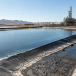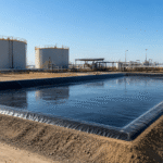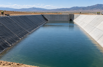
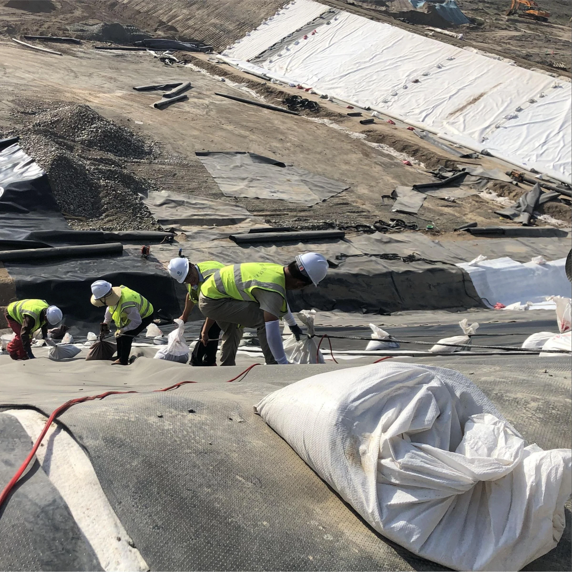

Biogas digesters are the core components of anaerobic digestion systems, with methane accounting for 60%-70% of the produced gas volume and a global warming potential 25 times that of CO₂. Once the barrier system fails, daily methane leakage can reach 15-30 standard cubic meters, directly affecting environmental and economic benefits.
Gas Permeability
Material Selection
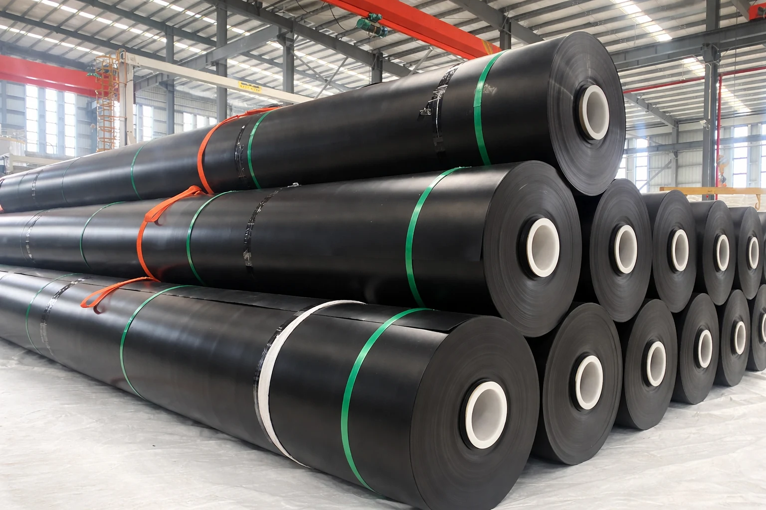
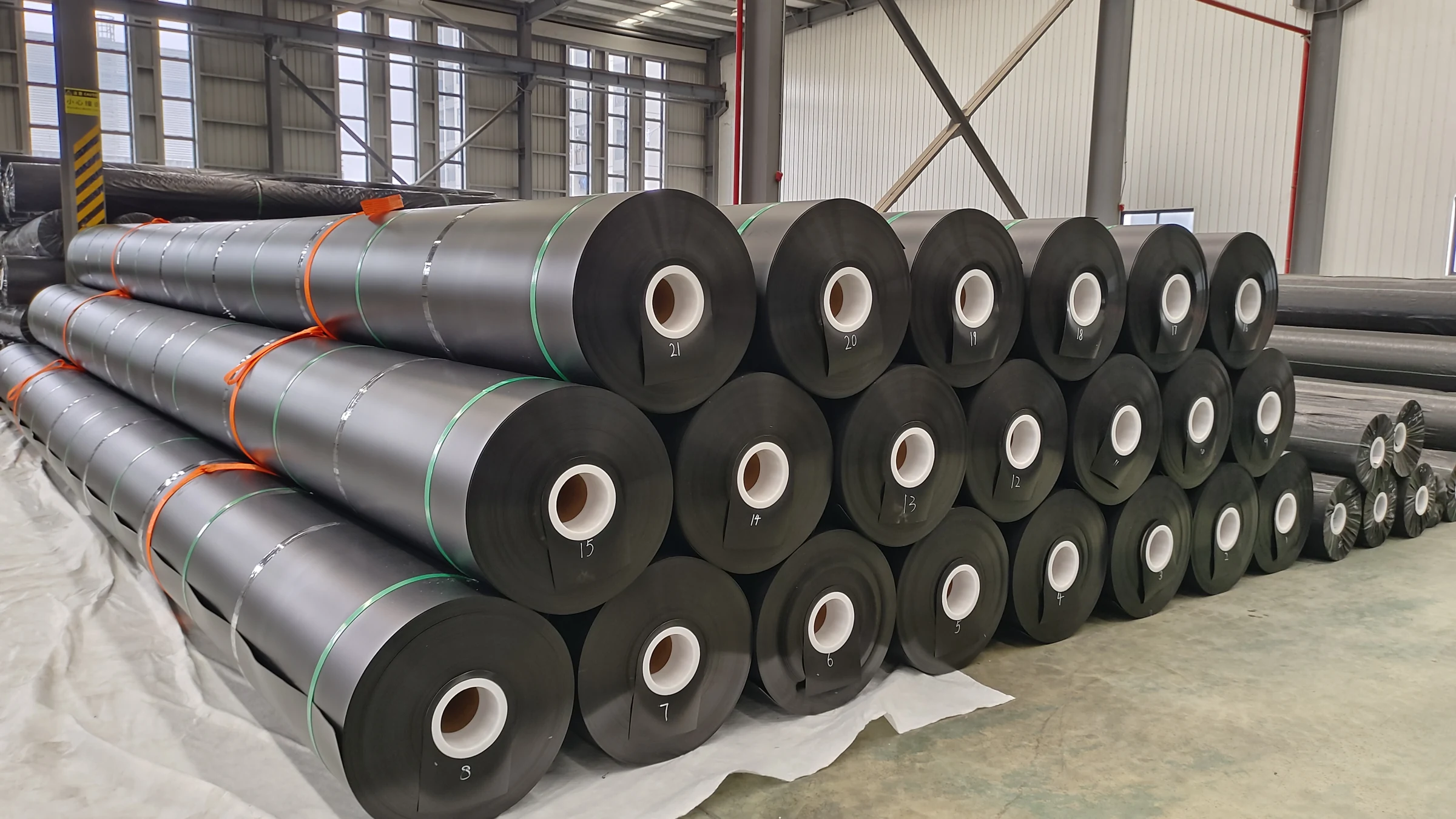
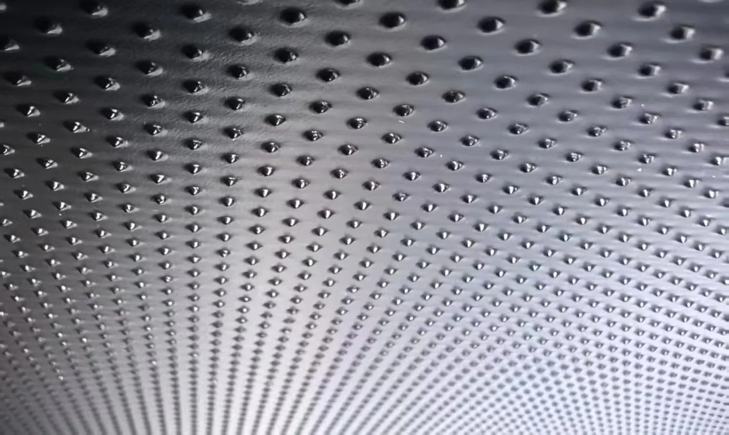
The core material for biogas digester methane barrier layers is geomembrane. Currently, the mainstream products on the market are HDPE (High-Density Polyethylene), LDPE (Linear Low-Density Polyethylene), EPDM (Ethylene Propylene Diene Monomer), and PVC (Polyvinyl Chloride). The following provides a horizontal comparison from four dimensions: **thickness range**, **tensile strength**, **chemical resistance**, and **applicable temperature**:
| Material | Thickness Range | Tensile Strength | Chemical Resistance | Applicable Temperature |
| HDPE | 0.75-3.0mm | ≥20MPa | Excellent (acid and alkali resistant) | -40℃ to +80℃ |
| LDPE | 0.5-2.5mm | ≥10MPa | Good | -30℃ to +70℃ |
| EPDM | 1.0-3.0mm | ≥7.5MPa | Excellent (ozone and aging resistant) | -40℃ to +120℃ |
| PVC | 0.5-2.0mm | ≥12MPa | Moderate (vulnerable to strong acids and alkalis) | -20℃ to +60℃ |
In terms of methane barrier efficiency, the methane permeability coefficient of HDPE material under standard conditions (temperature 25℃, pressure 1atm) is approximately 1×10⁻¹³ to 5×10⁻¹² cm³·cm/cm²·s·Pa, making it the **lowest gas permeability** choice among the four materials. LDPE has a slightly higher permeability coefficient, approximately 3-5 times that of HDPE. EPDM rubber, due to unsaturated double bonds in its molecular chain, has a permeability coefficient approximately 10-100 times that of HDPE, but excels in ozone and aging resistance compared to HDPE.
Large-scale biogas projects should prioritize HDPE as the primary barrier layer. EPDM rubber, due to its excellent elasticity and aging resistance, is commonly used for sealing edges and flexible joints of flexible covers. When PVC is in prolonged contact with high-concentration hydrogen sulfide (H₂S) in biogas environments, plasticizer migration occurs, causing the membrane to become hard and brittle. Its design lifespan is typically 5-10 years shorter than HDPE, so PVC is not recommended for the primary barrier layer of biogas digesters. During material procurement, suppliers should be required to provide quality certificates conforming to GRI-GM13 or equivalent standards, and batch sampling inspections should be conducted, focusing on thickness uniformity and tensile strength.
Thickness Impact
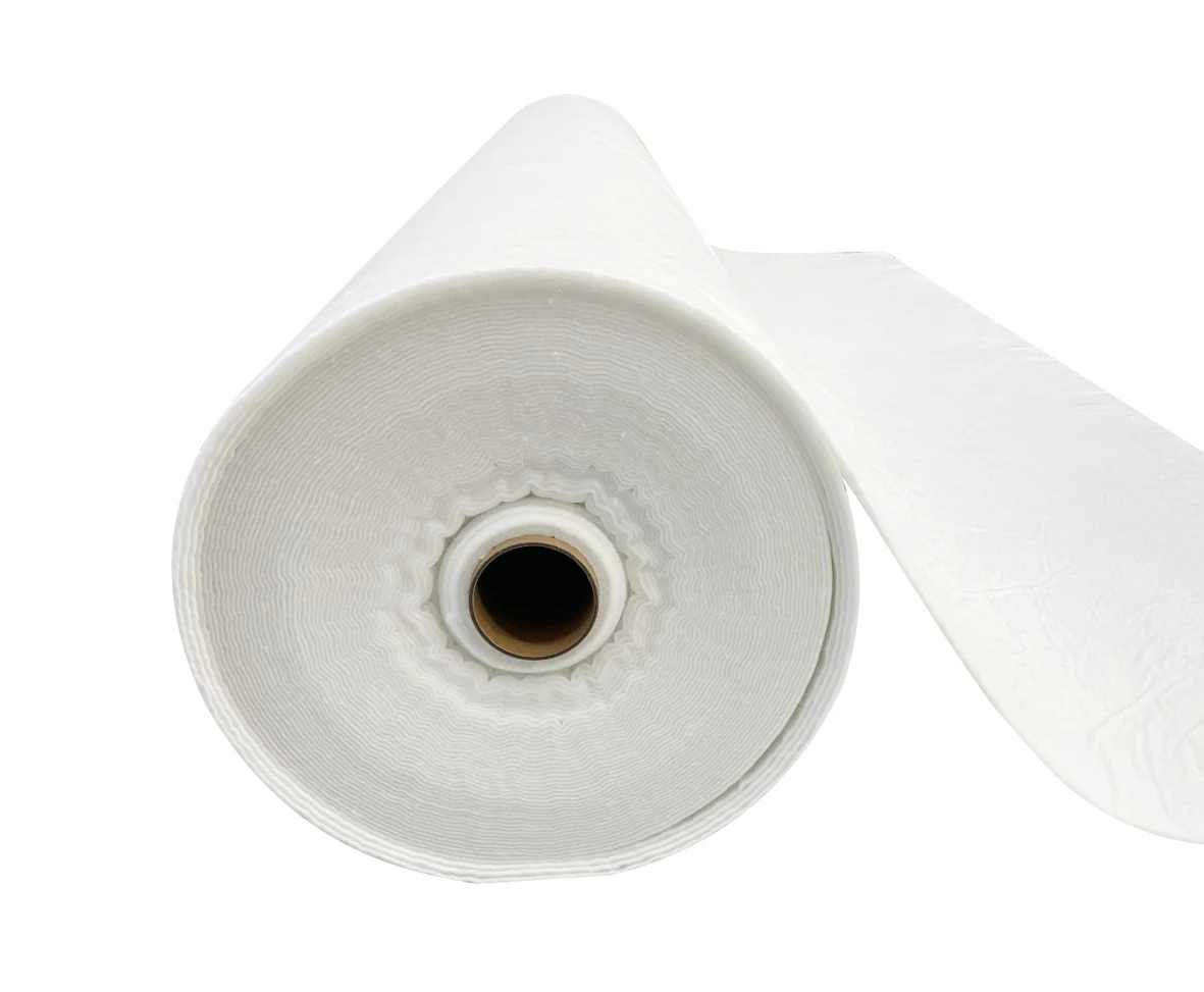
The thickness of geomembrane is a key parameter determining methane barrier efficiency and engineering costs. Taking HDPE as an example, conventional thickness specifications are five types: 1.0mm, 1.5mm, 2.0mm, 2.5mm, and 3.0mm. Industry test data indicates:
- When thickness increases from 1.0mm to 2.0mm, methane permeability decreases by approximately 40%-50%, but this is not a strictly linear relationship—the higher crystallinity of thicker geomembranes in the production process means the barrier performance improvement exceeds the thickness increase
- When thickness exceeds 2.5mm, hot-melt welding construction difficulty significantly increases, making seam quality difficult to guarantee, which increases leakage risk
- Geomembranes that are too thin (≤0.75mm) are highly susceptible to puncture damage during on-site handling and installation
- Every 0.5mm increase in thickness raises material cost by approximately 15%-20%, but seam labor costs may increase by 30%-40%
Considering barrier performance and construction feasibility, large-scale biogas digesters recommend **1.5-2.0mm HDPE** as the economic and safe balance range. In northern cold regions where tank burial insulation is required, thickness can be appropriately increased to 2.5mm. For projects with high groundwater levels, it is recommended to lay GCL (Geosynthetic Clay Liner) beneath the geomembrane to form a double-layer barrier system. Even if the upper HDPE layer is partially damaged, the sodium-based bentonite in the lower GCL will expand upon contact with water to seal leakage pathways. When selecting thickness, foundation bearing capacity should also be considered—heavier geomembranes (above 2.0mm) have better adaptability to uneven settlement of the tank bottom foundation, reducing membrane stretching damage caused by foundation deformation.
Methane Leakage Risks
The risk sources of biogas digester methane leakage can be divided into three categories: **membrane permeation**, **seam defect leakage**, and **pipe penetration/anchoring failure**. Among these, membrane permeation under normal operating conditions is extremely small, with main risks concentrated at seams and penetration points.
According to research data from the European landfill cover field, methane daily flux in soil-covered areas without any barrier layer can reach 500-5,000 g/m²/day, while properly installed HDPE barrier layers can control flux below 5 g/m²/day—a difference of over a hundredfold. The methane leakage risk distribution in biogas digesters exhibits a clear “Pareto principle” (80/20 rule) characteristic—approximately 80% of leakage issues occur at 20% of specific locations, including:
- Incomplete fusion of welded seams, presenting a “false weld” state, particularly at the arc-starting and arc-ending positions of hot-wedge welding
- Aging and cracking of sealants at pipe penetrations through tank walls (feed pipes, discharge pipes, biogas pipes), with rubber expansion joints hardening and losing elasticity
- Loosening of flexible cover anchoring system causing sealing interface separation, with anchor bolts loosening or pressure plates deforming
- Sudden temperature changes during operation (temperature drops greater than 30℃/hour) causing uneven shrinkage cracks between the geomembrane and concrete tank walls
- Sharp foreign objects falling into the tank during construction (rebar ends, construction debris) puncturing the geomembrane after commissioning water filling
It is recommended to conduct quarterly methane concentration survey mapping (using photoacoustic spectroscopy detectors) to promptly locate leakage hotspots, which can maintain annual methane recovery rate above 90%. For large-scale biogas stations with daily biogas production exceeding 500m³, installation of online methane concentration monitoring systems linked with combustion flares is recommended. When methane concentration falls below 45%, automatic ignition and combustion should be triggered to prevent low-concentration methane from being vented directly to the atmosphere.
Seam Integrity
Welding Methods
Geomembrane seam quality directly determines the reliability of the entire containment system. There are two standard welding processes for HDPE geomembranes:
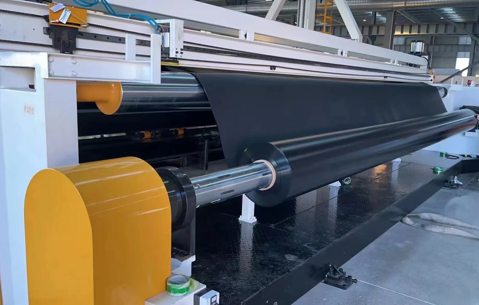
- Hot melt extrusion welding: HDPE raw material particles are heated to a molten state at 190℃-230℃ and uniformly extruded onto the seam of two sheets of membrane through a welding torch. The weld tensile strength can reach 80%-100% of the base material strength, with typical overlap width of 75-150mm. This process demands high operator skill; moving the welding torch too fast results in insufficient fusion (forming “cold welds”), while moving too slow causes the membrane to burn and decompose. Practical guideline: welding torch travel speed should be controlled at 0.5-1.5m/min
- Hot wedge fusion welding: A heated wedge is used to simultaneously heat the contact surfaces of two HDPE sheets, achieving fusion under certain pressure. This process offers high efficiency and is suitable for large-area linear seams, with weld strength reaching over 90% of the base material. Hot wedge temperature is typically set at 400℃-450℃, with travel speed of 1.0-2.5m/min
- Extrusion welding (for reinforcement): Used for on-site repairs and welding of irregular sections, typically as a supplementary method to the first two processes
PVC geomembrane welding requires lower temperatures (220℃-280℃) and typically uses hot air welding, with seam efficiency approximately 50%-70% of the base material. EPDM rubber cannot be hot melt welded and must be bonded using specialized neoprene rubber adhesive or butyl rubber tape, with bond strength approximately 40%-60% of the base material. Surface cleanliness requirements are extremely strict—any oil, grease, or dust will cause microscopic defects at the bonding interface. For EPDM seams, it is recommended to apply an additional layer of 50mm wide EPDM self-adhesive tape over the bonded area for secondary protection.
Leak Testing
Each weld must undergo integrity testing before backfilling or covering. The main methods include:
- Vacuum box method: A vacuum box is placed over the weld, negative pressure is drawn to 5-10psi, and bubble formation is observed for 30-60 seconds. This method effectively detects through-thickness defects ≥0.5mm and is the preferred method for on-site quality control. Testing efficiency is approximately 200-400 linear meters per work day
- Air pressure testing method: Compressed air is introduced into the enclosed air channel formed by double welds to the design pressure (typically atmospheric pressure + 5-10psi), held for 5 minutes while monitoring pressure drop. A pressure drop ≤5% is considered acceptable. This method is suitable for detecting continuous linear weld integrity
- Spark testing method: A high-voltage electric field (15-30kV) is applied to the weld; discharge sparks occur at insulation damage points. This method offers high detection efficiency and is suitable for rapid scanning of large-area seams, but can only detect defects on conductive substrates and is prohibited during rainy weather to prevent false readings
- Ultrasonic guided wave method: Ultrasonic waves are propagated along the weld, and internal defects are determined based on waveform attenuation and reflection characteristics. Accuracy can reach over 90% of weld volume defects, but equipment cost is relatively high, typically used for important projects or third-party acceptance testing
- Vacuum leak rate method: After establishing negative pressure in an enclosed space, the leak rate change is monitored, with sensitivity reaching defect detection of 0.01mm. This method is particularly suitable for final acceptance testing after covered with fill soil or after installation is complete
On-Site Repair Procedures
When defects are detected, on-site repairs must be carried out according to the following standardized procedure:
- Step 1: Mark the defect location, circle the defect area with a colored marker and photograph for records. Remove surface contaminants from the geomembrane within 300mm around the defect area, including soil, oil, and water stains; allow to air dry naturally
- Step 2: Use a hot air gun or angle grinder (with nylon grinding disc) to roughen the surface to be repaired, increasing bonding strength. After grinding, surface roughness Ra should reach 3.2-6.3μm
- Step 3: Cut an HDPE patch that is 100mm × 100mm larger than the defect area, with all four corners having a radius ≥20mm to prevent stress concentration
- Step 4: Use extrusion welding to fuse the patch with the original membrane; the weld should be smooth and free of pores. Ambient temperature during welding should not be below 5℃, and relative humidity should not exceed 85%
- Step 5: After the weld cools, retest using the vacuum box method; confirm no leaks before putting into service. The retest area should cover the repair area plus 100mm surrounding range. Sign the repair report after acceptance
- Step 6: Establish repair records documenting defect location (coordinates or description), date, repair method, operator name, acceptance inspector, and test results. Repair records are incorporated into the biogas station operation and maintenance records and retained for a period no less than the equipment design life. For major repairs (defect area ≥0.1m²), three-party acceptance sign-off is recommended. All welding operators must hold valid certifications
Flexible Cover Design
Cover Movement Space
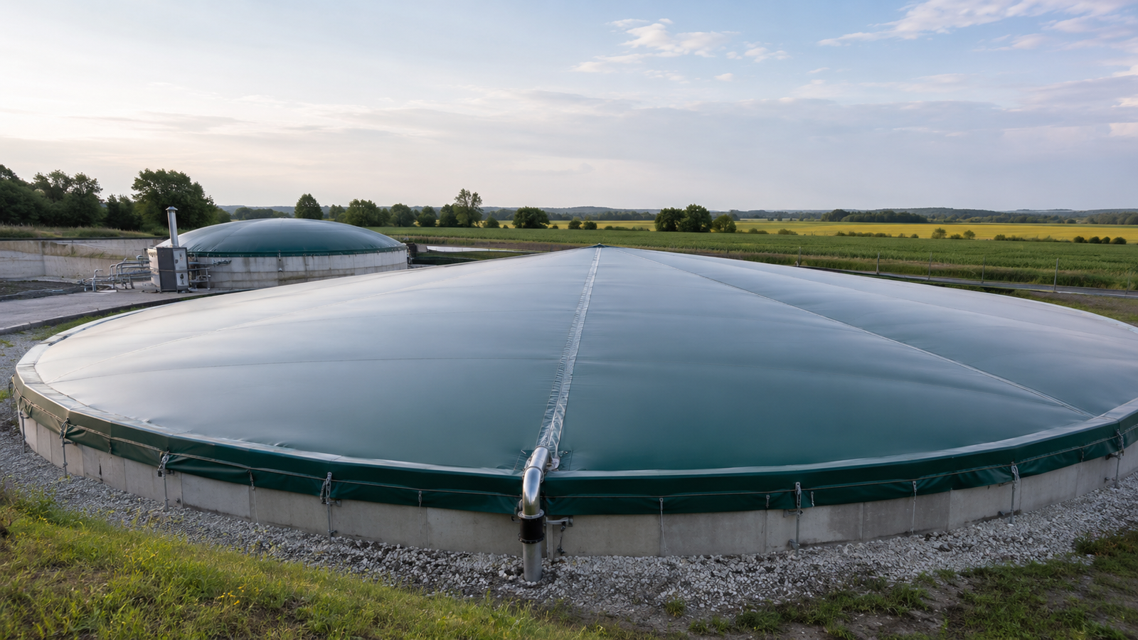
Flexible cover biogas tanks utilize the elasticity of geomembrane to achieve biogas collection and storage. The cover bulges upward when biogas fills the tank, and returns to its original position after biogas is discharged. Therefore, sufficient **movement clearance space** must be reserved between the cover and tank wall to prevent friction damage to the membrane during movement.
In engineering practice, the reserved width around the cover is typically 100-300mm; the gap between the cover and concrete tank wall is recommended to be ≥300mm. When the cover is fully inflated to the design maximum working pressure, the maximum displacement should be calculated according to the ideal gas state equation:
V_max = nRT / P_work, where n is the designed maximum amount of biogas, R is the gas constant, T is the operating temperature (Kelvin), and P_work is the upper limit of cover working pressure (typically 5-15mbar).
For large digesters exceeding 20 meters in diameter, it is recommended to install **guide rails** or **limit rope nets** on the inner side of the cover to guide vertical up-and-down movement and prevent membrane abrasion caused by lateral displacement. The contact areas between guide devices and membrane surface should be wrapped with neoprene rubber pads no less than 10mm thick to distribute contact stress within an acceptable range. For rapid pressure fluctuation conditions with daily pressure variation exceeding 5mbar (such as intermittent feeding digesters), the guide device should also have buffering function, which can be achieved by using spring-loaded pulley systems or pneumatic balancing cylinder structures. The cover movement space design should also reserve flexible connection segments for biogas pipelines penetrating the cover. Metal bellows or expansion joints are recommended, with length no less than 200mm, to accommodate relative displacement during cover movement.
Anchoring Methods
The anchoring connection between flexible cover and tank wall is a key node of the system, ensuring both airtightness and allowing the cover to expand and contract freely with pressure changes. There are three common anchoring forms:
- Sealed groove anchoring: The top of the concrete tank wall is pre-configured with dovetail or semi-circular grooves. The cover edge is embedded in the groove, and water is injected into the groove to form a water seal. This solution offers the best airtightness and is suitable for large biogas storage tanks, with design negative pressure resistance reaching -50mbar. The groove width is typically 2-3mm larger than the geomembrane thickness, and the depth is no less than 50mm.
- Flange clamp anchoring: The geomembrane edge is clamped with stainless steel or aluminum alloy pressing plates, and fixed to embedded components on the tank wall through bolts. An EPDM rubber gasket must be installed between the pressing plate and membrane body to distribute stress concentration. The flange pressing plates should adopt a split design to facilitate rubber gasket replacement without disassembling the main pressing plate.
- Weight anchoring: A weight steel pipe pocket is sewn onto the cover edge and filled with sand or iron ore sand. The membrane edge is pressed down by gravity. This method is simple and reliable, suitable for medium and small biogas tanks, but has higher requirements for the sealing design of biogas collection pipes. The weight mass is determined by calculating the combined force of local maximum wind pressure and biogas negative pressure, typically 5-15kg/m.
Regardless of the anchoring method used, a **stress buffering layer** (such as neoprene rubber gasket or non-woven geotextile) must be installed at all contact areas between the geomembrane and hard structures to prevent membrane tearing caused by excessive local stress. After the anchoring system is installed, a pressure retention test should be conducted at no less than 1.5 times the design pressure, with a holding time of no less than 24 hours, and the pressure drop must not exceed 5% of the design pressure.
Wear Protection
During long-term operation of the flexible cover, repeated friction between the cover edge and anchoring system is one of the main causes of membrane damage. Additionally, hydrogen sulfide (H₂S) in biogas has weak acidity, and if accompanied by condensation water adhering to the membrane surface, it will accelerate local aging. When H₂S concentration exceeds 500ppm, the corrosion rate of EPDM rubber will increase significantly.
In the contact area between the cover edge and anchoring components, it is recommended to install **high-density polyethylene wear strips** or **polyurethane protective pads** to distribute concentrated friction over a larger membrane surface area. The protective pad thickness is typically 5-10mm, and the width should be ≥150mm, fixed to the anchoring components with stainless steel bolts. The protective pad material should preferably be polyurethane with Shore A hardness of 70-85, whose wear resistance is approximately 3-5 times that of HDPE.
During regular inspections, the following areas should be given priority attention: the surface condition of the membrane under the anchoring pressing plates (checking for whitening, wrinkling, or thickness reduction), the contact area between guide devices and membrane surface (checking friction mark depth), and the membrane surface around biogas outlet pipes (checking star-shaped cracks caused by thermal stress concentration). If whitening, cracking, or thickness reduction signs appear on the membrane surface, the local membrane body should be replaced immediately, with the damaged area cut out and re-welded. The standard inspection cycle is every 3 months, which should be shortened to monthly under high-temperature or high H₂S operating conditions. With standardized maintenance, the design service life of flexible geomembrane covers can reach 15-25 years.
The reliability of biogas tank barrier systems is jointly determined by five key elements: material selection, thickness, welding, testing, and anchoring. Each link requires customized design based on specific project conditions to achieve the dual goals of greenhouse gas emission reduction and energy recovery.