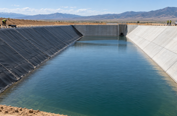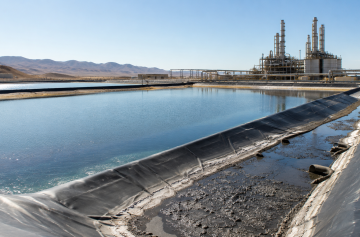
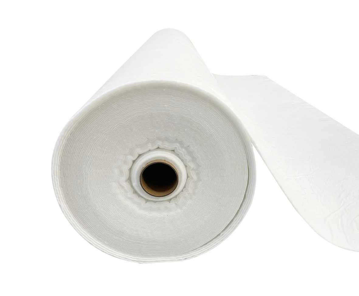

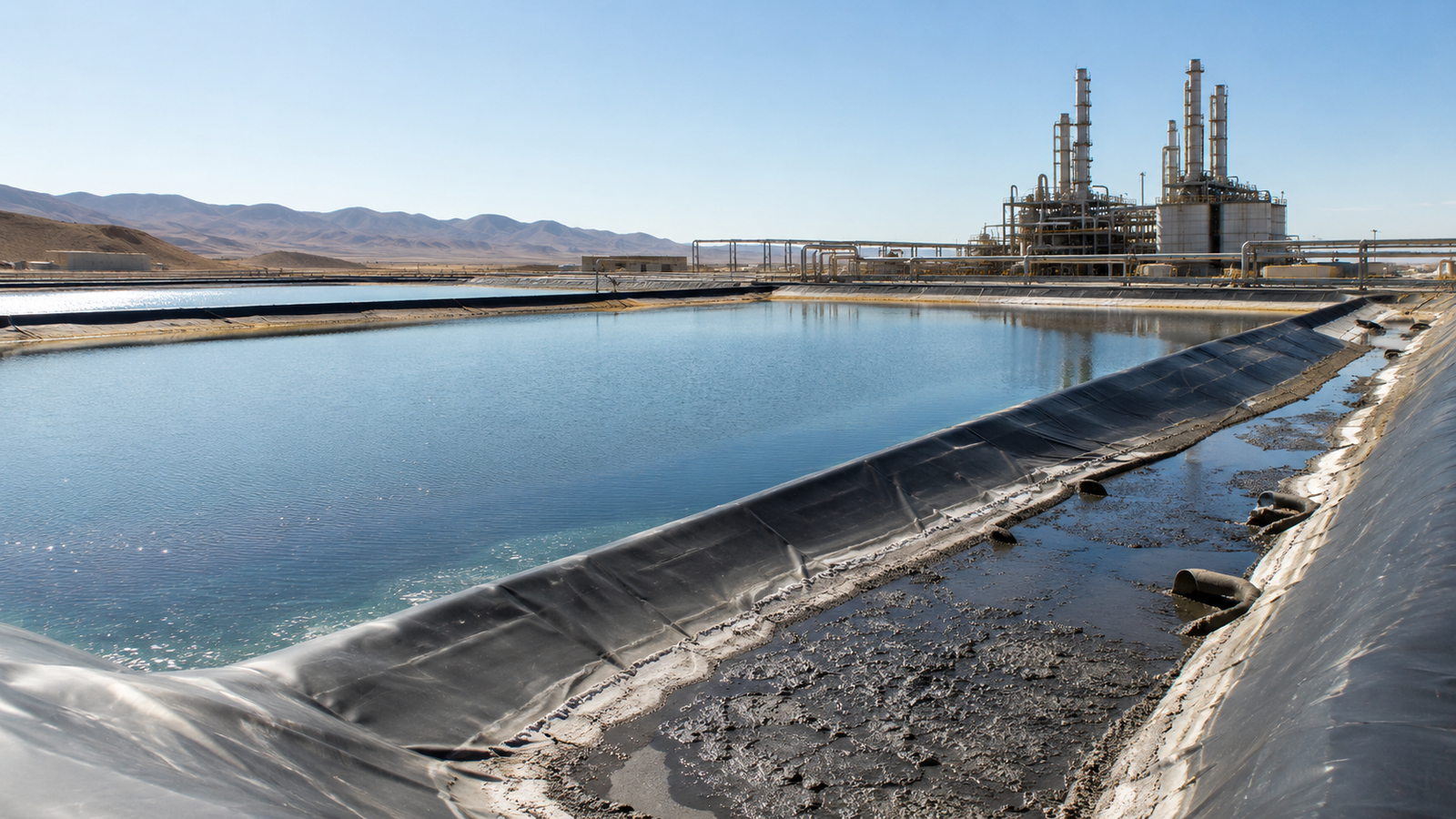
Industrial wastewater evaporation ponds are critical facilities for treating high-salinity effluent. A well-designed evaporation pond can operate for 25 years, but lining failures caused by improper material selection typically concentrate within 3 to 5 years, with repair costs reaching 2 to 3 times the original construction expense. This article examines key design and operational requirements across three dimensions: high-temperature stability, chemical compatibility, and sludge management.
High-Temperature Stability
High-Temperature Resistance
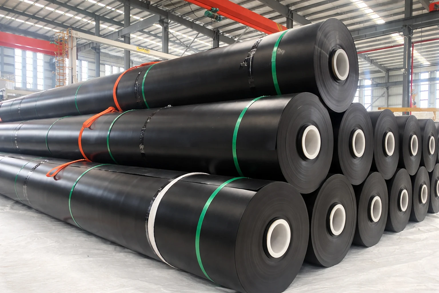
Industrial wastewater in evaporation ponds frequently runs well above ambient temperature. In petrochemical, metallurgical, and textile dyeing operations, effluent discharge temperatures regularly reach 60°C to 90°C, and some fine chemical plant waste acid stripping units exceed 100°C. HDPE (high-density polyethylene) geomembrane’s standard temperature ceiling is 70°C, governed by its crystal melting point (approximately 130°C) and thermal oxidative induction temperature. Prolonged exposure near or above 70°C drives HDPE into a high-elastic state, with significant reductions in hardness, puncture resistance, and tensile strength. A petrochemical plant’s wastewater equalization basin experienced HDPE thickness reduction from 2.0mm to 1.3mm after 18 months of operation at 82°C influent temperature without adequate cooling pretreatment, creating substantial leakage risk.
Vinyl ester resin glass flake coating (VEGF) is the dominant lining choice for high-temperature wastewater basins. With a vinyl ester resin binder and corrosion-resistant glass flake filler, VEGF sustains long-term service temperatures up to 200°C with short-term thermal shock resistance to 180°C. A Zhejiang PTA (purified terephthalic acid) wastewater treatment facility with continuous influent temperatures of 85°C to 95°C has operated for over 5 years without lining failure using HVEGF-200 vinyl ester glass flake coating. Wastewater exceeding 120°C requires PTFE lining or Hastelloy C-276 monolithic construction. PTFE spans -180°C to 260°C and is essentially insoluble in all solvents. For every 10°C that design wastewater temperature exceeds the HDPE ceiling, upgrade the lining system to glass flake or PTFE class—thickening HDPE delays softening but cannot raise the thermal deformation temperature ceiling.
Preventing UV-Induced Cracking
Most evaporation ponds operate outdoors, with surface temperatures climbing to 50°C–65°C under summer direct sunlight and dropping below 30°C at night—a diurnal temperature swing exceeding 25°C. This cyclic thermal stress places extreme demands on geomembrane weather resistance. Carbon black content in HDPE geomembrane is typically 2% to 3%, primarily absorbing ultraviolet radiation and suppressing photo-oxidative aging. Carbon black dispersion directly affects anti-aging performance—zones with uneven light shielding develop microcracks within 3 to 5 years. Per GRI-GM13 standard, HDPE geomembrane carbon black dispersion must achieve Grade 1 or 2 (10× magnifier inspection), delivering outdoor service life of 20 to 25 years. Weld zones are UV aging’s weakest point: the high temperature of fusion welding re-crystallizes carbon black distribution near the seam, reducing UV resistance below that of the parent material. An evaporation pond in northwest China showed significantly elevated weld cracking rates in Year 4, ultimately requiring large-scale membrane replacement by Year 6.
Core measures for preventing UV-induced cracking are:
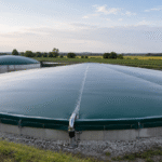
- Install a floating cover system on the pond surface to reduce direct UV exposure causing surface aging and lower in-pond water evaporation simultaneously
- Apply additional UV-protective coating over weld zones to strengthen local weather resistance
- Prefer black HDPE geomembrane over white or light-colored varieties—black grades have more uniform carbon black distribution
Selecting Heat-Resistant Linings
Heat-resistant lining selection for evaporation ponds must integrate temperature, medium, and mechanical load considerations. Common heat-resistant lining materials by temperature class are:
| Material Type | Long-Term Temperature Range | Suitable Wastewater Scenarios |
|---|---|---|
| HDPE Geomembrane | -70°C to +70°C | Low-temperature or ambient industrial wastewater, domestic sewage |
| PVC Geomembrane | -15°C to +60°C | Industrial wastewater with low acid/alkali concentration |
| PVDF Film | -40°C to +150°C | Fluorine-containing wastewater, high-temperature acidic wastewater |
| Vinyl Ester Glass Flake (VEGF) | Up to +200°C | Petrochemical and pharmaceutical high-temperature wastewater |
| PTFE / Hastelloy | -180°C to +260°C | Strongly corrosive high-temperature liquid waste, concentrated acids and alkalis |
Thermal expansion coefficient differences also demand attention—HDPE linear expansion coefficient is approximately 200×10⁻⁶/°C versus approximately 10×10⁻⁶/°C for concrete tank walls, a 20-fold disparity. Under a 50°C temperature differential, HDPE membrane linear contraction can reach 10mm/m; inadequate anchorage design easily creates stress concentration at anchoring zones, leading to membrane tearing. For large evaporation ponds, LLDPE geomembrane with elongation at break up to 800% is preferred over standard HDPE, providing superior elastic recovery after thermal expansion deformation. LLDPE’s puncture resistance exceeds HDPE by approximately 30%, with elongation at break above 800%, enabling better accommodation of foundation deformation from uneven settlement—making it the preferred lining for large evaporation ponds on soft ground. Beyond temperature resistance, PVDF film offers exceptional fold resistance—it can be folded at -40°C without cracking, well-suited for evaporation ponds in northern seasonal freeze-thaw environments.
For evaporation ponds with average daily wastewater temperature exceeding 55°C or instantaneous temperature exceeding 80°C, prioritize VEGF glass flake or higher-grade linings rather than relying solely on thickened HDPE. Regarding lining thickness selection within the same material system: thicker linings provide greater corrosion allowance and higher safety factors—2.0mm HDPE has a design service life of approximately 25 years; increasing to 2.5mm raises the allowance by 50% while adding only 15% to 20% to cost, delivering outstanding value.
Chemical Compatibility
Understanding Wastewater Types
Wastewater fed to industrial evaporation ponds varies enormously in composition—chemical compatibility mismatches reduce lining lifespan by 50% at minimum and cause rapid perforation and leakage at worst. Based on primary pollutants, industrial wastewater falls into four categories:
| Wastewater Type | pH Range | Representative Industries | Primary Corrosion Mechanism |
|---|---|---|---|
| Acidic Wastewater | pH < 4 | Petrochemical, metal acid pickling, ore processing | Oxidative degradation; corrosion rate approximately doubles per 10°C temperature increase |
| Alkaline Wastewater | pH > 10 | Textile dyeing, soap manufacturing, aluminum processing | High-concentration NaOH above 60°C creates stress cracking risk |
| Oily Wastewater | Contains petroleum or animal/vegetable oils | Oil extraction, machining, food processing | Aromatic solvents accelerate HDPE swelling and mechanical property deterioration |
| High-Salinity Wastewater | TDS > 5,000 mg/L | Coal chemical, salt industry, coastal industry | Chloride ions accelerate corrosion of glass fiber reinforcement layers |
Acidic wastewater corrosion rates on HDPE and PVC are extremely low at ambient temperature (annual corrosion depth < 0.1mm), but oxidative degradation rate approximately doubles per 10°C increase. For strong acid environments below pH 2, HDPE thickness should be increased to a minimum of 2.5mm to provide corrosion allowance. Oily wastewater containing aromatic solvents (benzene, toluene, xylene) with aromatic content exceeding 5% is unsuitable for direct HDPE lining. Before determining lining materials, obtain at least one complete hydrological year’s wastewater quality monitoring report, with particular attention to pH, temperature, COD, ammonia nitrogen, TDS, and characteristic pollutant concentrations, to be incorporated as design input into the technical specification.
Matching Lining Materials
Glass-reinforced plastic (GRP) linings based on four major corrosion-resistant resin types—epoxy resin, bisphenol A epoxy vinyl ester resin, isophthalic epoxy vinyl ester resin, and saturated polyester resin—are the most mature anti-corrosion solution for industrial wastewater basins. Bisphenol A epoxy vinyl ester resin offers the best overall performance, demonstrating excellent resistance to acids, alkalis, and salts; at temperatures below 70°C, it withstands virtually all concentration ranges of sulfuric acid, hydrochloric acid, and sodium hydroxide solutions. Isophthalic epoxy vinyl ester resin operates approximately 20°C higher than bisphenol A type but with slightly inferior strong-acid resistance, suitable for alkaline or neutral wastewater environments. Saturated polyester resin is lowest in cost but its temperature ceiling is only 120°C and it is not recommended for strong acid or alkali environments.
Differences in flexural modulus across resin systems directly affect lining deformation resistance—bisphenol A epoxy vinyl ester resin has a flexural modulus of approximately 13GPa, isophthalic type approximately 12GPa, while saturated polyester reaches only 10GPa. For evaporation ponds with risk of uneven foundation settlement, prioritize bisphenol A or isophthalic resins with higher flexural modulus. One practical method for verifying lining selection appropriateness: consult successful case histories from the same industry and wastewater type with no lining failures after more than 5 years of operation. High-salinity wastewater: GRP linings should use isophthalic resin rather than orthophthalic resin—chloride ions accelerate corrosion of the glass fiber reinforcement layer in orthophthalic resin systems.
Practical matching principles are:
- High-temperature acidic wastewater (above 60°C): prefer bisphenol A epoxy vinyl ester resin GRP with minimum 6mm thickness
- High-temperature alkaline wastewater: isophthalic epoxy vinyl ester resin GRP is acceptable
- Oily wastewater containing aromatic solvents: replace HDPE geomembrane with PVC or FPP (flexible polypropylene) membrane
Checking Leakage Risks
Once an evaporation pond leaks, remediation costs far exceed constructing a new facility. Per US EPA Subtitle D regulations, the pond bottom must incorporate an impermeable system with a maximum leakage rate of 0.27 L/m²/day. In practice, leakage concentrates at three vulnerable locations: welds, anchorage edges, and penetrations.
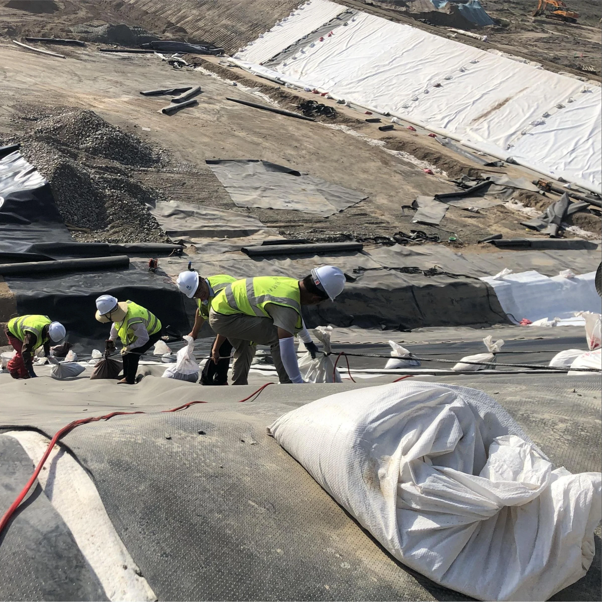
Welds are the primary leakage source—dual-track fusion weld peel strength must reach no less than 70% of parent material strength; improper welding parameter control causes incomplete fusion. During pressure testing of a coal chemical industrial park evaporation pond, 7 of 32 welds (21.9%) failed peel strength qualification. Anchorage edges under thermal cycling with insufficient design margin create failure modes where membrane stretches and detaches from anchoring profiles. Penetrations constitute the third highest-risk location due to the material discontinuity between membrane and pipe surfaces combined with challenging interface treatment.
Core measures for reducing leakage risk are:
- Welds must undergo dual-inspection protocol—contractor self-inspection followed by independent third-party testing via spark test or vacuum box test
- Anchorage edge design must provide no less than 5% deformation margin
- Penetration locations require a professional detail: pre-embedded casing plus double-seal ring
- Pre-commissioning leakage testing for no less than 72 hours, monitoring both bottom seepage pressure gauges and online water quality instruments
Sludge Management
Developing a Sludge Removal Plan
During evaporation pond operation, insoluble solids (SS) continuously concentrate and crystallize, forming sludge deposits on the pond bottom. Without timely removal, increasing sludge layer thickness reduces effective volume and evaporation efficiency; anaerobic conditions also generate hydrogen sulfide and other toxic gases, threatening operator safety. A large coal chemical industrial park evaporation pond with 5,000m² effective volume experienced average sludge deposition at approximately 150mm/year, with design volume reduced by approximately 30% by Year 4 due to sludge occupation.
A sound sludge removal plan must establish the following three key parameters:
- Anticipated sludge accumulation rate: for every 100mg/L increase in influent SS concentration, annual average sludge deposition thickness increases approximately 15mm to 20mm
- Removal operation window: typically during the season of lowest evaporation (winter in northern regions or rainy season in southern regions), when low liquid level minimizes production impact
- Sludge disposal destination: must be identified in the plan to prevent secondary pollution from temporary stockpiling
Removal methods vary by sludge moisture content: moisture above 85% uses remote sludge pump suction; 60% to 85% uses high-pressure water jet dilution followed by suction; below 60% uses grab excavator for dry sludge hauling. The removal plan must specify post-cleaning lining inspection items for each de-sludging event—including visual inspection (identifying scratches or punctures), spark testing (focusing on mechanically damaged zones), and thickness measurement (comparing against original design thickness to calculate consumed corrosion allowance).
Protecting the Pond Bottom
The pond bottom is the most vulnerable plane in the entire impermeable system. Heavy de-silting equipment (sludge grabs, excavators) traveling or operating on the pond bottom causes deep scratches or punctures in the HDPE geomembrane that are difficult to detect visually. Industry statistics show that over 60% of evaporation pond leakage incidents are directly related to de-sludging operations, with approximately 40% occurring during first equipment entry into the basin.
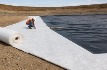
Core bottom protection measures involve installing a protective layer on the geomembrane surface—the standard approach applies a nonwoven geotextile cushion (minimum 600g/m²) over the HDPE geomembrane, topped with a 50mm to 80mm fine-aggregate concrete protective layer. Concrete thickness depends on de-sludging equipment weight: tracked equipment exceeding 5 tonnes requires a minimum 80mm protective layer; wheeled equipment under 2 tonnes can be reduced to 50mm but must be supplemented with temporary steel plates to distribute ground pressure.
Another commonly overlooked issue is uneven foundation settlement. Evaporation ponds are typically built on backfill or soft ground, where differential settlement may develop over years of operation, causing concrete protective layer cracking and loss of geomembrane protection. Design phase should establish settlement monitoring points on the pond bottom, with bi-annual surveys during operation; when settlement differential exceeds 50% of the design value, immediate foundation reinforcement is required. No de-sludging operations may be conducted in settlement zones prior to foundation reinforcement—geomembrane in differential settlement zones is already in a tension state, and additional loads from de-sludging equipment readily cause tearing.
Maintaining Access Passages
The passage system of an evaporation pond comprises influent pipes, sludge discharge pipes, overflow channels, and inspection access routes. Influent pipe scaling or blockage causes uneven wastewater distribution and abnormal local liquid levels, reducing evaporation efficiency; sludge discharge pipe blockage prevents normal sludge removal during de-silting operations, forcing open manual entry basin cleaning with greatly elevated safety risk; overflow channel blockage causes pond water overflow during storm events, carrying high-concentration pollutants into the external environment—a major environmental hazard.
The core passage maintenance strategy is “prevention over remediation”—influent and sludge discharge pipes should use DN300 or larger diameter to reduce blockage probability; flushing connections should be installed at pipe bends and reducers with flushing at least weekly. Overflow channel outlets must prevent high-velocity water erosion; inspection access routes should be hardened and maintained intact to prevent rain-induced muddy conditions from blocking personnel access to the pond perimeter.
Operational maintenance essentials are:
- Establish a passage inspection log system, conducting endoscopic inspection of influent and sludge discharge pipes quarterly, recording wall scaling thickness and deposit status to schedule preventive flushing based on findings
- Clear overflow channel debris monthly
- Increase overflow channel cleaning frequency before storm seasons
High temperature accelerates corrosion rates, sludge promotes local erosion, and point leaks can destroy lining integrity within three months—investing an additional 10% in selection research during the design phase reduces operating period leakage repair expenditure by 80%.