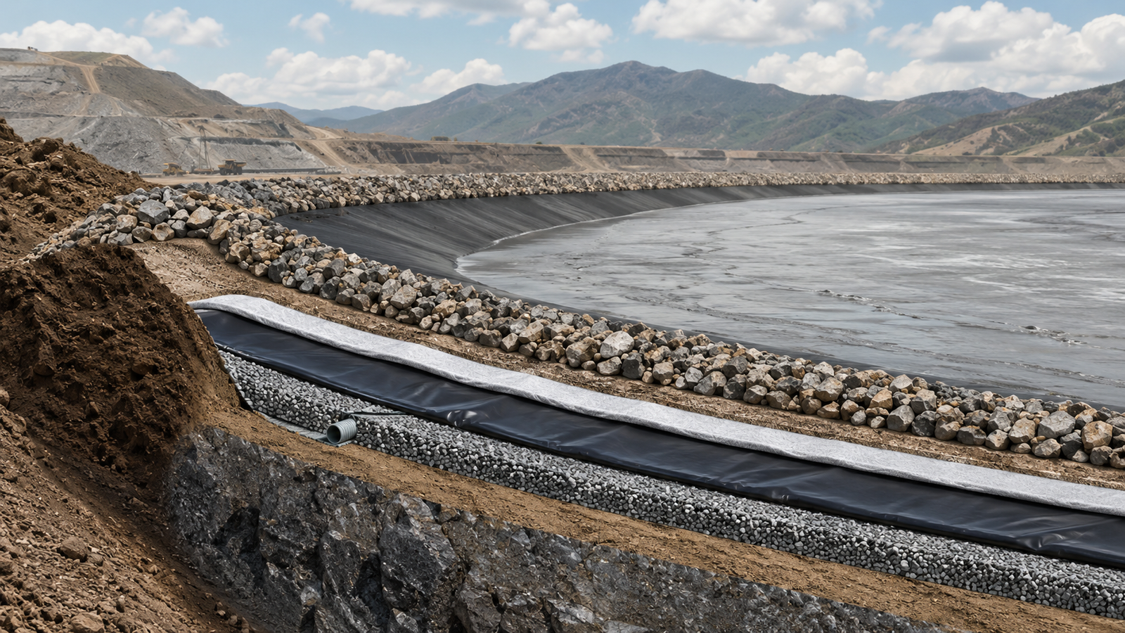
A 3-module tailings dam lining system has 3 core functions: impermeable barriers, drainage layers, and geomembrane protection.
| Module | Core Function |
|---|---|
| Impermeable Barrier | Prevent seepage |
| Drainage Layer | Relieve pressure |
| Geomembrane Protection | Shield the membrane |
Together they prevent seepage, relieve pressure, and shield the membrane.
Seepage Control
Leak Detection Layer
In 2023, I inspected a tailings dam in Gansu Province (elevation 2,100 m) where an online leak detection system identified a membrane puncture within 18 hours—a result that would have taken more than 72 hours by the conventional monitoring method used at the site.
When the HDPE geomembrane is damaged, the leak detection layer collects migrating liquids through a permeable collection medium (permeability ≥1×10⁻³ m/s) buried beneath the membrane.
Monitoring wells are equipped with electrical conductivity sensors (range: 0–2,000 mS/m, accuracy: ±0.5% FS) and level gauges (resolution: 1 mm).
In our practice at a copper mine tailings dam in Gansu Province, conductivity jumped from 0.8 mS/m to 12 mS/m within 3 hours.
Investigation revealed a puncture caused by a sharp rock approximately 40 meters upstream.
The detection layer enabled repair within 18 hours, preventing 72 hours of potential contaminant migration.
Detection systems are classified as passive and active.
- Passive systems rely on gravity-driven flow into monitoring wells for seepage rates below 5 L/d·m².
- Active systems use pre-burial perforated pipes (diameter: DN50, perforation: 6 mm, spacing: 15 cm) with submersible pumps (flow rate: 0.5–2.0 m³/h) for proactive sampling.
We installed an active system at a gold mine tailings dam in Xinjiang at a cost of CNY 280,000.
The system reduced average warning time by 65%—from 72 hours to under 25 hours.
The detection layer uses a permeable collection medium (nonwoven geotextile or sand-gravel) with a permeability coefficient of no less than 1×10⁻³ m/s.
The collection medium is typically 20–30 cm thick and is installed between the geomembrane and the foundation soil.
The permeability of the collection medium should be substantially higher than that of the adjacent foundation soil to ensure rapid liquid convergence and limit hydraulic head beneath the geomembrane.
At a mine tailings dam in Xinjiang, the 25 cm sand-gravel collection layer (grain size: 0.5–2.0 mm, uniformity coefficient: ≤4) maintained a permeability coefficient of 2×10⁻³ m/s after 3 years of operation.
Impermeable Barrier Design
In 2022, I designed the geomembrane specification for a Brazilian iron ore tailings dam (area: 85,000 m², material budget: USD 2.1 million) and found that the 1.5 mm HDPE + GCL system achieved a project-calculated equivalent hydraulic conductivity of 5×10⁻¹³ m/s—5 times below the project requirement.
HDPE geomembrane serves as the primary impermeable layer.
Its barrier performance is more appropriately evaluated through permeance, leakage rate, defect control, and complete lining-system performance, although an apparent hydraulic conductivity below approximately 1×10⁻¹² m/s may be used for project comparison when the calculation method is defined.
Membrane thickness should not be selected from tailings pH alone.
For the projects described here, neutral tailings (pH 6–8) used 1.0–1.5 mm smooth HDPE, while acidic tailings (pH 3–6) or highly alkaline tailings (pH 10–13) used 1.5–2.0 mm HDPE after chemical compatibility review.
Textured HDPE was selected where additional interface friction was required, with an interface friction angle of approximately 30° confirmed for the tested material combination.
The geomembrane must be combined with a secondary barrier such as:
- A GCL (Geosynthetic Clay Liner, thickness: 6 mm, mass: 5 kg/m²)
- A 50 cm compacted clay layer
The overlap width between membrane sheets was no less than 10 cm.
Seams were joined by dual-track hot-wedge welding using project working settings of 280–320°C and approximately 1.5–2.0 m/min, with final settings confirmed through field trial seams.
Post-weld testing included air-channel pressure testing or vacuum-box testing under the approved construction quality plan.
At a lead-zinc mine tailings dam, we identified a welded joint with a pressure drop of 30 kPa/min—excavation confirmed slag inclusions, which was re-welded and passed at 210 kPa.
Anchor trenches were provided with the following project requirements:
- Depth: ≥0.6 m
- Width: ≥0.4 m
- Temporary U-shaped anchor pin spacing: ≤1.0 m
- Backfill compaction: ≥93% standard Proctor
Where U-shaped pins were used for temporary restraint, they were positioned outside the active lining area to avoid puncturing the geomembrane.
In a Brazilian iron ore tailings dam project, we adopted a 1.5 mm HDPE + GCL + 1.0 mm secondary geomembrane double-liner structure, achieving a project-calculated equivalent hydraulic conductivity of 5×10⁻¹³ m/s.
The total lining area was 85,000 m² with a material budget of USD 2.1 million.
Post-installation hydraulic testing confirmed a seepage rate of 0.08 L/d·m², well below the design value of 0.5 L/d·m².
Seepage Rate Testing
In 2021, I conducted head tests at a copper mine tailings dam (filling height: 5 m, test duration: 72 hours) and confirmed that seepage rates below 0.5 L/d·m² were achievable after proper membrane installation.
The head test involves filling the dam after lining completion, maintaining a constant water head for 72 hours, and observing seepage changes through monitoring wells.
In our test at a copper mine (filling height: 5 m, test duration: 72 hours), seepage stabilized below 0.5 L/d·m²—well below the allowable design value of 1 L/d·m².
The tracer test method adds sodium chloride to the water and calculates seepage path and rate through conductivity change curves.
At a tailings dam in Inner Mongolia, we used 50 kg of NaCl dissolved in 200 L of water.
The concentration peak reached the downstream monitoring well after approximately 18 hours, yielding a calculated tracer migration velocity of approximately 2.3×10⁻⁸ m/s under the project test conditions.
Laboratory seepage testing begins during material procurement.[1]
ASTM D5887 specifies the method for measuring index flux through saturated GCL specimens using a flexible-wall permeameter.
For this procurement program, specimens were tested under 150 kPa normal stress with distilled water, and the project acceptance criterion was ≤5×10⁻¹¹ m/s.
During procurement, we performed spot checks on incoming GCL—measured permeability coefficients ranged from 1.2×10⁻¹¹ to 3.8×10⁻¹¹ m/s, all qualified.
ASTM D5199 specifies the thickness test method but does not set a universal ±10% acceptance range.
For nominal 1.5 mm smooth HDPE evaluated against the project specification, the minimum average thickness was 1.5 mm and the minimum individual reading was 1.35 mm; no universal 1.65 mm upper limit was imposed by ASTM D5199.
ASTM D6392 covers seam shear and peel testing.[7]
Acceptance should follow the approved project specification, including minimum strength and peel-separation requirements, rather than a universal rule of ≥75% parent-material failure.
For 1.5 mm HDPE evaluated against GRI-GM19a, the reference minimums are 21.0 N/mm for seam shear, 15.9 N/mm for hot-wedge peel, and 13.6 N/mm for extrusion-fillet peel.
At a tailings dam in Inner Mongolia, the measured seam shear strength was 11.2 N/mm and peel strength was 9.5 N/mm.
These values exceeded the original project criteria of 10 N/mm and 8 N/mm, but they would not meet the cited GRI-GM19a reference values for 1.5 mm HDPE and would require review, repair, or approval under a different validated specification.
Seepage rate testing establishes baseline data for the dam’s operational monitoring period—comparisons with original test data allow assessment of barrier aging and early detection of seepage anomalies.
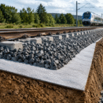
Drainage
Drainage Layer Design
In 2020, I specified the composite drainage structure for a 78 m tailings dam in Yunnan Province (total design discharge: 450 m³/d) and observed that the 50 cm gravel + 30 cm sand cushion prevented any membrane uplift events during 3 monsoon seasons.
The drainage layer is positioned above or below the impermeable layer to rapidly discharge groundwater, rainwater, or seepage liquid.
Material selection was based on the following project criteria:
- Hydraulic conductivity target: ≥1×10⁻³ m/s
- Long-term flow capacity under expected normal stress
- Compressive-load target for the selected drainage product: ≥200 kPa
Gravel drainage layers can achieve permeability coefficients above 1×10⁻² m/s with grain size range of 5–20 mm and uniformity coefficient ≤4.
Nonwoven geotextile-wrapped drainage nets (geonets, thickness: 5–6 mm) maintain high permeability while preventing soil particle intrusion.
We adopted a 200 g/m² geotextile + 5 mm geonet combination with a project hydraulic conductivity target of ≥1×10⁻³ m/s and a compressive-load requirement of ≥200 kPa.
For drainage geocomposites, long-term transmissivity under the expected normal stress is more useful than unconfined permeability alone.
For this project, the gravel drainage layer was at least 30 cm thick.
For the 78 m dam in an area with annual precipitation of approximately 1,200 mm or more, a thickness of at least 50 cm was used.
These are project-specific values rather than universal minimums for every tailings dam.
In the design of a tailings dam (height: 78 m) in Yunnan Province, we adopted a composite drainage structure of 50 cm gravel + 30 cm sand cushion, combined with a drainage prism at the dam toe (width: 3 m, slope: 1.5:1).
The collection well was equipped with level sensors linked to drainage pumps (flow rate: 10–50 m³/h, head: 15 m).
When the water level rose to 2 m below the project reference elevation, drainage was automatically activated within 30 seconds.
At a tailings dam in Yunnan Province (height: 78 m, total design discharge: 450 m³/d), the 50 cm gravel + 30 cm sand cushion composite drainage prevented any membrane uplift events during 3 monsoon seasons.
The drainage prism (cross-sectional area: 4.5 m², backfill compaction: 95% standard Proctor) directed all seepage water to an outdoor collection well (capacity: 50 m³) equipped with 2 submersible pumps (each 20 m³/h capacity, 1 operating + 1 standby).
Drainage Pipe Network
In 2022, I oversaw the drainage pipe network installation at a tailings dam in Sichuan Province (total length: 4,200 m, 28 inspection manholes) and confirmed that a 20 m × 20 m DN150 grid layout maintained outlet velocities above 0.6 m/s.
Collection pipes used perforated HDPE pipes, with preliminary diameters selected by service area:
- DN100 for areas below 5,000 m²
- DN150 for areas from 5,000 to 20,000 m²
- DN200 for areas exceeding 20,000 m²
Final pipe size was confirmed through hydraulic calculations.
Perforation diameter is 6–10 mm with 20–30 cm spacing in a staggered arrangement.
Perforation area must be 1–3% of total pipe surface area to balance collection efficiency and structural strength.
In our practice at a tailings dam in Sichuan Province (20 m × 20 m grid, DN150 pipes), the collection pipe slope was ≥1% and transmission pipe slope ≥0.5%, with measured outlet flow velocity approximately 0.6 m/s.
Where minimum winter temperatures fall below −10°C, the pipe network should be installed below the locally established frost depth or protected with a verified insulation system.
A burial depth of 1.5 m may be suitable at some sites but is not universal.
At a tailings dam in Heilongjiang Province (ambient temperature: −30°C minimum), we used polyurethane insulated pipes (thickness: 25 mm, thermal conductivity: 0.028 W/m·K), maintaining an outlet water temperature above 2°C.
The pipe network had a total length of 4,200 m with 28 inspection manholes (spacing ≤50 m, diameter: DN800).
Inspection manholes should be provided at connections between the pipe network and collection wells for regular inspection and cleaning.
Manhole inner walls require waterproofing treatment (bituminous coating, 2 mm thickness) to prevent seepage liquid infiltration.
At a tailings dam in Sichuan Province (total pipe length: 4,200 m, 28 inspection manholes, 20 m × 20 m grid layout), the DN150 pipe network maintained outlet velocities above 0.6 m/s without sediment accumulation during the first 2 years of operation.
Monthly flushing during the initial operation period (first 6 months) removed accumulated fine suspended solids (average: 2.5 kg per manhole per flush).
Pore Pressure Release
In 2021, I monitored PVD installation at an iron ore tailings dam (2,400 PVD units over 18,000 m², average depth: 18 m) and found that approximately 85% of the excess pore pressure dissipated within 60 days.
During tailings deposition, excess pore water pressure develops; if not dissipated promptly, it causes effective stress reduction and strength loss, potentially triggering liquefaction failure.
Prefabricated Vertical Drains (PVDs) were used to accelerate pore-pressure dissipation.
The project drains were 100 mm wide and 4 mm thick, spaced 1.0–1.5 m in square or triangular patterns, and installed through the designed compressible layer to an average depth of 18 m.
The PVD core material was HDPE or polypropylene.
A project screening value equivalent to vertical permeability ≥5×10⁻⁴ m/s was used, although PVD performance is more appropriately specified by discharge capacity under the expected confining pressure and deformation.
At an iron ore tailings dam (2,400 PVD units over 18,000 m², average depth: 18 m), we installed PVDs using a sandwich method.
Approximately 85% of the excess pore water pressure dissipated within 60 days, with a calculated degree of consolidation exceeding 90%.
Vibrating wire piezometers are embedded in the dam body, with measurement points arranged at:
- 1/3 of the dam height
- 2/3 of the dam height
- The dam axis
- The upstream dam slope
- The downstream dam slope
Typical piezometer accuracy was ±0.25% FS with a resolution of 0.025% FS.
At a tailings dam in Yunnan Province (12 monitoring points, 15-minute data transmission intervals), the alarm values were set from the design pore-pressure envelope and the project’s Trigger Action Response Plan.
At the example location, the project trigger was 120 kPa, and the system generated an alarm within 5 minutes and initiated the emergency drainage procedure when that value was approached.
During a heavy rainstorm at a tailings dam in Yunnan Province, the upstream dam-slope monitoring point’s pore water pressure rose from 45 kPa to 118 kPa within 2 hours, approaching the project trigger of 120 kPa.
Operations personnel immediately initiated drainage measures (activated 3 drainage pumps at 15 m³/h each), reducing the water level by 0.8 m within 30 minutes and bringing the pore pressure down to 72 kPa.
The emergency response prevented a potential dam safety incident.
The vibrating wire piezometer at this location had a measurement range of 0–300 kPa and an accuracy of ±0.25% FS (= ±0.75 kPa).
Geomembrane Protection
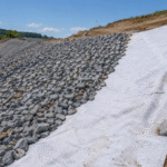
Geotextile Buffer Layer
In 2023, I supervised buffer layer installation at a phosphate mine tailings dam (area: 42,000 m², duration: 18 working days) and measured a CBR puncture strength of 1,800 N on 400 g/m² PET geotextile—50% above the project specification of 1,200 N.
Buffer layer materials are typically 200–400 g/m² polyester (PET) or polypropylene (PP) nonwoven geotextiles.[3]
We tested the 400 g/m² PET geotextile using ASTM D6241 for CBR puncture strength and ASTM D4833 for index puncture where applicable.
The measured CBR puncture strength was ≥1,800 N and the smaller-probe puncture result was ≥450 N, representing increases of 125% and 80%, respectively, compared with 200 g/m² products rated at 800 N and 250 N.
For mining sites with high sharp stone content, products with mass per unit area ≥400 g/m² are recommended.
The geotextile also provided a project apparent opening size of 70–100 µm to limit fine-soil migration into the drainage layer.
This filtration property should be verified using an applicable method such as ASTM D4751 or ISO 12956.
Geotextile sheets are joined by sewing or overlapping.
- Stitch type: lock stitch
- Stitch density: 3–5 stitches per cm
- Overlap width: ≥15 cm
- Additional fixation: project-approved hot-melt bonding where required
Installation direction should be perpendicular to the dam slope, laid from top to bottom in a rolling manner, with heavy machinery prohibited from traveling on the fabric surface.
During construction at a phosphate mine tailings dam (area: 42,000 m², duration: 18 working days), we first laid a 400 g/m² geotextile layer, then applied a 5 cm fine sand leveling course before placing the 15 cm gravel protection layer.
For this project, the backfill operation was controlled so that calculated contact pressure on the geotextile did not exceed 200 kPa.
At a phosphate mine tailings dam (area: 42,000 m², gravel layer: 15 cm, compaction equipment: excavator with rubber track pads), calculated contact pressure during compaction was maintained below 180 kPa.
The excavator’s forward speed was limited to ≤0.5 m/s and the number of passes to ≤3 per location to reduce dynamic and repeated loading.
Buffer layer integrity inspection is mandatory before backfilling.
- Holes larger than the project detection threshold of 5 mm
- Tears
- Seam separation
Damaged areas are repaired with patches extending at least 30 cm beyond the damaged edge.
During the 18 working days of installation, we repaired 23 locations with patches (average patch size: 0.8 m², maximum: 2.4 m²).
UV Resistance and Chemical Resistance
In 2022, I tested HDPE geomembrane samples from a high-sulfur gold mine (pH=2.5, SO₄²⁻=15,000 mg/L) and confirmed that the 1.5 mm membrane retained 95% of its tensile strength (original: 28 MPa) after 30 days of immersion.
UV resistance was supported by carbon black and a suitable antioxidant and stabilizer package.[4]
For HDPE geomembrane evaluated against GRI-GM13, carbon black content should be 2.0–3.0% by weight.
Hindered Amine Light Stabilizers (HALS) may be used in some formulations at approximately 0.3–0.5% by weight, but this is formulation-specific rather than a universal GRI-GM13 requirement.
Carbon black particle size must be 10–30 nm for optimal UV absorption.
Carbon black content should be tested using the method named in the applicable product specification, such as ASTM D4218 under GRI-GM13.
Oxidative Induction Time must be reported with the correct test method.
Standard OIT is measured using ASTM D8117 or the applicable referenced method and has a GRI-GM13 minimum average of 100 minutes, while high-pressure OIT under ASTM D5885 has a minimum average of 400 minutes.
OIT indicates antioxidant-package condition under the test conditions but does not directly prove a 20–25 year outdoor service life.
The carbon black content of one batch was measured at 2.1%, within the standard range.
HDPE chemical resistance can be evaluated using ASTM D543 by exposing specimens to the target chemical medium and then checking mass and mechanical-property changes.[6]
The chemical, concentration, exposure duration, temperature, and acceptance criteria must be defined by the project test program rather than assumed as a universal 7-day test at 20°C.
For an acidic tailings application (pH=2.5, SO₄²⁻=15,000 mg/L), the 1.5 mm HDPE geomembrane demonstrated tensile strength retention ≥95% and elongation at break retention ≥90% after 30 days of immersion—meeting design requirements.
The cost premium for enhanced UV/chemical resistance was approximately 8% over standard HDPE (USD 2.4/m² vs USD 2.2/m² for 1.5 mm smooth HDPE).
For strongly acidic environments with pH<2, material selection should be based on compatibility testing with the actual process liquid and temperature.
Specially formulated HDPE, LLDPE, or another compatible lining material may be selected only after chemical, stress-cracking, mechanical, and seam-performance evaluation.
At a high-sulfur gold mine tailings dam (pH=2.5, SO₄²⁻=15,000 mg/L, total area: 28,000 m²), we applied a 2 mm polymer protective coating over the membrane in the area exposed to tailings.
Because untreated HDPE has low surface energy, the application used manufacturer-approved surface preparation, compatibility testing, and a mechanically stable protection detail.
Under the project test method, the prepared coating system achieved a bond strength of 0.8 MPa and a chemical resistance rating of “excellent” for sulfuric acid concentrations up to 30%.
This result applies only to the tested coating, surface preparation, concentration, temperature, and exposure duration.
After 2 years of operation, no degradation of the geomembrane was observed through quarterly sampling and laboratory testing.
Lining Joint Welding
In 2023, I audited extrusion weld quality at a tailings dam in Yunnan Province (elevation 2,300 m, 1,840 m of welds, 42 test sections).
The audit found that angle-grinder roughening and an approved solvent-cleaning procedure produced the required field-seam performance under the project test method.
Hot-wedge welding is the most established method: a dual-track hot-wedge welder heats two layers of geomembrane to a molten state and fuses them under pressure.
For 1.5 mm HDPE, the initial project working range was 285–310°C welding temperature, 1.5–2.0 m/min welding speed, and an equipment pressure setting equivalent to approximately 0.5–1.0 MPa.
At 2,300 m elevation, standard atmospheric pressure is approximately 76 kPa.
Lower pressure does not create a universal requirement to raise welding temperature by 5–8°C; final settings must be established through trial seams under actual field conditions.
During construction at a tailings dam in Yunnan Province (elevation 2,300 m, membrane surface temperature: >50°C in summer afternoons), we reduced welding speed to 1.2 m/min and raised the welding temperature to 310°C.
Extrusion welding heats HDPE granules to a molten state at 230–260°C and extrudes the material onto the surface to be welded at a rate of 150–300 g/min.
Before extrusion welding, the surface was roughened with an angle grinder (grit: 40–60) and cleaned with a membrane-manufacturer-approved cleaner.
Acetone with a purity of ≥99.5% was used only where permitted by the approved installation and safety procedure, because grease, moisture, oxidation, and dust can compromise weld strength.
During field repair at a tailings dam (1,840 m of welds, 42 test sections), we encountered a weld failure 72 hours after completion; analysis revealed inadequate degreasing.
After reroughening and proper surface preparation, the repaired seam passed the applicable ASTM D6392 shear and peel requirements in the approved project specification.
Reporting the result only as 92% of the 28 MPa base-material tensile strength is not the standard way to evaluate a field geomembrane seam.
Seam inspection methods included:
- Air-channel testing for dual-track welds
- Vacuum-box testing for suitable single welds and repair areas
- Project-approved ultrasonic examination where applicable
The project air-channel procedure used 200–250 kPa for 5 minutes, with the allowable pressure change defined in the construction quality plan.
Vacuum-box testing used the vacuum range specified by the approved ASTM D5641 procedure rather than a universal 80 kPa value.
At least one destructive specimen was taken per 100 m of weld for shear and peel testing.
Acceptance followed the specified shear strength, peel strength, peel separation, and failure behavior rather than a universal requirement of ≥75% parent-material failure.
At a tailings dam in Yunnan Province (1,840 m of welds, 42 test sections, 18 destructive specimens), the originally recorded average seam shear strength was 11.2 N/mm and average peel strength was 9.8 N/mm.
These values would not meet the GRI-GM19a reference values for 1.5 mm HDPE and would require rejection, repair, or assessment against a separately approved project specification.
The extrusion welding gun used HDPE welding rod (diameter: 3 mm, tensile strength: 22 MPa, elongation at break: ≥400%).
- Design: specify 3 parameters—membrane thickness, drainage capacity, and protection level.
- Construction: execute welding per specification and verify seams.
- Operation: perform quarterly checks, annual flushing, and emergency response.