LLDPE geomembrane is used in containment projects where the liner must tolerate movement, bending, settlement, and complex geometry. Compared with stiffer geomembranes, LLDPE provides higher flexibility and elongation, making it suitable for floating covers, settlement-prone basins, pipe penetrations, curved slopes, and irregular structures. Typical project thicknesses often range from 1.0 mm to 2.0 mm, depending on chemical exposure, UV conditions, puncture risk, welding details, and service requirements. Material selection should be supported by subgrade preparation, seam testing, anchoring, drainage design, and routine inspection rather than relying on flexibility alone.
Floating Covers
LLDPE geomembrane is used for floating covers where the liner must move with changing water levels, gas pressure, wave action, and thermal expansion. In reservoirs, wastewater ponds, anaerobic lagoons, and industrial containment basins, typical cover thicknesses often range from 1.0 mm to 2.0 mm, depending on exposure, panel size, wind load, and maintenance access. Compared with stiffer HDPE, LLDPE provides higher flexibility and elongation, helping the cover conform around floats, ballast tubes, pipe penetrations, and perimeter anchor zones. Design checks should include buoyancy spacing, rainwater drainage, gas venting, seam testing, UV resistance, and edge anchoring.
Flexible Cover Movement
A floating cover is not a static liner. It moves as the liquid level rises and falls, air temperature changes, gas accumulates below the cover, and wind pushes the surface. LLDPE geomembrane is selected because it can tolerate repeated flexing better than a rigid lining material when the project includes variable water elevation or irregular cover movement.
| Design Factor | Engineering Check | Why It Matters |
|---|---|---|
| Liquid level variation | Normal operating range and maximum drawdown | Prevents excessive tension at the perimeter |
| Cover slack | Allowance for vertical movement | Reduces strain near seams and penetrations |
| Thermal expansion | Day-night and seasonal temperature change | Limits wrinkling, folding, and stress concentration |
| Gas pressure | Venting path and gas collection points | Prevents uncontrolled ballooning under the cover |
| Rainwater load | Drainage sump or pump location | Reduces ponding weight on the membrane |
LLDPE floating covers are commonly used in municipal water storage reservoirs, wastewater treatment ponds, anaerobic lagoons, and industrial containment basins. In these projects, the cover may reduce evaporation, limit sunlight exposure, control odor, separate process liquid from rainfall, or support gas management. The exact function depends on the facility design and operating conditions.
Stress often concentrates at perimeter clamps, pipe boots, access hatches, seams around floats, and ballast connections. These areas require extra detailing because repeated movement can damage weak details faster than the open field area of the geomembrane.
- Keep the cover surface free from sharp tools, stones, welding debris, and metal offcuts.
- Avoid dragging panels across rough subgrade or concrete edges.
- Use rounded transitions near fixed structures.
- Confirm that factory or field seams are tested before operation.
- Allow controlled slack instead of pulling the cover tight during installation.
Buoyancy and Ballast Layout
A floating cover must stay stable on the liquid surface. Flexibility alone is not enough. The cover also needs a controlled system of floats, ballast weights, drainage paths, gas vents, and access points. Poor float spacing can create sagging areas; poor ballast layout can create over-tension; poor drainage can allow rainwater to collect and overload the membrane.
| Component | Function | Design Note |
|---|---|---|
| Float system | Supports cover geometry and access zones | Spacing depends on cover weight, water level movement, and maintenance load |
| Ballast tubes or weights | Controls cover position and wind movement | Hard contact with the geomembrane should be avoided |
| Drainage sump | Collects rainwater from the cover surface | Pump sizing should match local rainfall assumptions |
| Gas vents | Releases trapped gas under the cover | Location depends on pond geometry and gas generation rate |
| Access walkway | Allows inspection and maintenance | Requires load review and reinforced details |
Buoyancy layout should distribute load, not simply keep the membrane floating. The cover may need to carry rainwater, limited maintenance traffic, tension from wind movement, and concentrated loads near fittings. Where access is required, additional support or reinforcement is usually needed.
Ballast should be placed where it controls movement without cutting, pinching, or overstressing the membrane. Direct contact between hard ballast elements and unsupported LLDPE should be avoided. In higher-risk zones, a compatible protection layer or reinforced strip can reduce abrasion.
- Float spacing that is too wide can create deep sagging and water ponding.
- Ballast spacing that is too heavy or concentrated can strain seams and perimeter details.
- Insufficient drainage slope can leave standing water on the cover.
- Poor gas venting can lift the cover unevenly.
- Walkways should not rely on unsupported membrane strength.
Wind Uplift and Edge Anchoring
Floating covers are exposed to wind uplift, especially on open reservoirs, lagoons, and large wastewater ponds. Wind can lift loose cover sections, create flutter, move ballast lines, and increase stress at the perimeter. LLDPE helps because it can flex, but wind resistance depends mainly on anchoring, ballast layout, edge detailing, and cover geometry.
| Area | Inspection Point | Risk If Ignored |
|---|---|---|
| Perimeter edge | Anchor trench depth, clamp continuity, or curb fixing | Cover pullout or edge lifting |
| Corners | Extra stress from wind and geometry change | Tearing or seam strain |
| Pipe penetrations | Boot flexibility and clamp seal | Leakage or local stress damage |
| Access hatches | Reinforcement and seal detail | Water entry or cover distortion |
| Ballast lines | Position and contact protection | Abrasion or uncontrolled cover movement |
Perimeter anchoring should be designed for the site, not copied from a generic detail. Open terrain, pond size, local wind speed, liquid level range, and freeboard all affect the anchor demand. The anchoring system may include an anchor trench, batten bar, concrete curb, clamp system, or a combination of mechanical and buried restraint details.
- Confirm anchor trench dimensions or mechanical fixing details before deployment.
- Check that the edge detail allows expected water level movement.
- Inspect corners for folds, trapped stress, and sharp transitions.
- Verify that pipe penetrations use flexible boots or compatible detailing.
- Test seams near the perimeter because these areas often experience higher handling stress.
- Inspect after strong wind events, especially during the first operating season.
Settlement Areas
LLDPE geomembrane is used in settlement-prone areas where the liner must tolerate subgrade deformation without losing containment performance. These conditions may appear in wastewater ponds built on soft soils, landfill cells with compressible waste layers, mining process ponds, sludge lagoons, and basins constructed over variable fill. Typical LLDPE liner thicknesses often range from 1.0 mm to 2.0 mm, depending on chemical exposure, puncture risk, slope geometry, and design life assumptions. The engineering focus includes subgrade preparation, wrinkle control, seam orientation, strain allowance, geotextile cushioning, drainage stability, and post-installation inspection after settlement occurs.
Subgrade Movement Tolerance
Settlement areas create a different loading condition from stable concrete or compacted structural fill. The geomembrane may need to move with the surface below it as the foundation consolidates, waste compresses, or embankment fill adjusts under hydraulic load. LLDPE is often selected because it offers better flexibility than HDPE in applications where controlled deformation is expected.
| Project Area | Settlement Source | Liner Design Concern |
|---|---|---|
| Wastewater ponds | Soft clay, organic soil, uneven compaction | Local stretching and ponding |
| Landfill cells | Waste compression and differential movement | Seam strain and slope transition stress |
| Sludge lagoons | Low-bearing subgrade and deposited solids | Long-term deformation under wet loading |
| Mining process ponds | Fill zones, embankment movement, operational loading | Anchor stress and liner bridging |
| Industrial basins | Variable backfill near structures and pipe zones | Stress around penetrations |
The liner should not be expected to bridge voids or compensate for poor earthwork. Before installation, the subgrade needs to be shaped, compacted, and cleared of sharp stones, roots, debris, and abrupt grade changes. Soft areas should be identified before deployment because a localized depression can create high strain after the basin is filled.
- Review surface smoothness before liner deployment.
- Remove angular stones, roots, and construction debris.
- Prepare stable slope transitions between floor and sidewall.
- Review compaction in fill zones and embankments.
- Control drainage to avoid subgrade softening.
- Protect pipe trenches and concrete interfaces.
Seam Strain Control
Seams are usually less tolerant of deformation than the open field area of the geomembrane. In settlement areas, seam layout must be planned to reduce tensile strain, avoid stress concentration, and keep welded joints away from locations with expected movement. Good seam design is a layout, installation, and inspection issue, not only a welding issue.
| Seam Factor | Recommended Control | Reason |
|---|---|---|
| Seam direction | Align seams with lower-strain movement where possible | Reduces direct tension across welded joints |
| Slope transition | Avoid seams at sharp grade changes | Limits bending and peel stress |
| Pipe zones | Use flexible detailing and reinforced boots | Reduces stress near fixed penetrations |
| Anchor trench area | Keep seam termination controlled and protected | Prevents pull stress at restraint points |
| Field welding | Test trial seams and production seams | Confirms weld quality before operation |
LLDPE panels should be placed with enough slack to handle expected movement, but not so much that folds become trapped under liquid load. Excessive wrinkles can create wear points, interfere with seam testing, and collect sediment. A balanced installation leaves controlled movement allowance without creating permanent folds.
- Complete trial welds before production welding.
- Inspect seam continuity visually.
- Use air pressure testing for dual-track fusion seams where applicable.
- Use vacuum box testing where specified.
- Take destructive seam samples at approved intervals.
- Document patches, caps, extrusion welds, and repair testing.
ASTM D6392 is commonly used to evaluate geomembrane seam strength in peel and shear testing. The project specification should define acceptance requirements, test frequency, repair procedures, and documentation format before installation begins. Field teams should not judge seam acceptance by appearance alone.
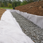
Geotextile Protection Layer
Settlement areas often need a geotextile protection layer because flexible movement can increase contact stress between the geomembrane and the subgrade. A PET continuous filament non-woven geotextile can provide cushioning, separation, filtration, and puncture protection when the liner is placed over compacted soil, prepared fill, gravelly zones, drainage layers, or irregular surfaces.
| Condition | Geotextile Function | Design Review |
|---|---|---|
| Angular soil particles | Cushioning below geomembrane | Mass per unit area and puncture resistance |
| Soft subgrade | Separation and support | Survivability during installation |
| Drainage layer | Filter and separation layer | Apparent opening size and flow capacity |
| Settlement depression | Stress distribution | Reduces point loading under the liner |
| Maintenance traffic | Temporary surface protection | Requires controlled access plan |
A geotextile does not replace subgrade preparation. It reduces puncture and abrasion risk, but it cannot correct unstable soil, exposed sharp rock, deep rutting, or poor compaction. The subgrade still needs acceptance before geotextile placement.
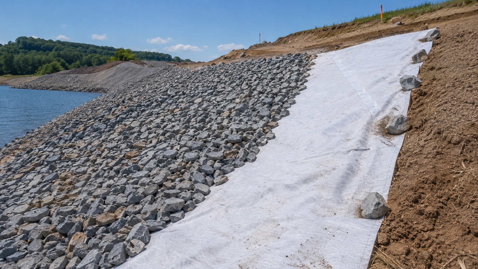
- Use geotextile below the geomembrane to reduce puncture from subgrade particles.
- Use geotextile above the geomembrane where ballast, gravel, soil cover, or maintenance work may contact the liner.
- Consider double-sided protection in high-risk zones such as sumps, pipe corridors, access ramps, and drainage trenches.
- Add localized reinforcement around penetrations, corners, and slope transition areas.
Irregular Structures
LLDPE geomembrane is used around irregular structures where the liner must conform to corners, curved surfaces, pipe penetrations, sumps, baffles, ramps, and concrete interfaces without excessive stress. In these areas, the design issue is not only waterproofing; it is strain control around fixed points and changes in geometry. Typical thickness selection often falls within 1.0 mm to 2.0 mm, depending on chemical exposure, installation access, puncture risk, and welding detail complexity. Compared with stiffer liners, LLDPE can adapt better to tight shapes, but successful performance still depends on prepared surfaces, compatible boots, reinforced patches, qualified welding, seam testing, and routine inspection.
Corners and Pipe Penetrations
Corners and pipe penetrations are high-stress zones because the geomembrane changes direction or connects to a fixed structure. In ponds, wastewater basins, secondary containment areas, and industrial sumps, these details often include concrete walls, outlet pipes, inlet sleeves, overflow structures, pump stations, and anchor terminations.
| Detail Area | Main Engineering Concern | Recommended Control |
|---|---|---|
| Inside corners | Wrinkling, bridging, trapped stress | Use rounded transitions and controlled panel layout |
| Outside corners | Tension concentration | Avoid tight pulling during deployment |
| Pipe penetrations | Movement between liner and fixed pipe | Use flexible boots, clamps, and reinforced patches |
| Concrete interfaces | Abrasion and restraint stress | Use smooth surfaces and compatible termination details |
| Sumps and outlets | Complex shape and maintenance contact | Add localized protection and inspection access |
Pipe penetrations require more attention than flat field seams. The liner must seal around the pipe while still allowing small movement caused by settlement, thermal expansion, liquid loading, or operational vibration. A rigid connection can transfer stress directly into the geomembrane.
- Prepare a clean and smooth pipe surface before boot installation.
- Use a compatible geomembrane boot or prefabricated sleeve.
- Add reinforcement around the penetration zone.
- Select a clamp or termination detail suitable for the pipe material.
- Use sealant only where specified, not as a substitute for welding.
- Complete visual inspection and leak testing where the detail allows.
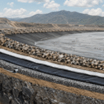
Tight Slopes and Curved Surfaces
Tight slopes and curved surfaces appear in channels, containment berms, process ponds, tanks, embankment transitions, and retrofit lining projects. These surfaces are difficult because the geomembrane must follow changes in angle, radius, elevation, and restraint. LLDPE is often preferred when the structure includes curves or non-standard geometry that would place excessive strain on a rigid liner.
| Surface Condition | Risk | Control Method |
|---|---|---|
| Tight radius curve | Local stretching or folding | Use smaller panels or shaped panel layout |
| Steep slope | Down-slope movement during deployment | Use temporary weighting and controlled anchoring |
| Slope-to-floor transition | Bending and seam stress | Keep seams away from sharp transition zones |
| Retrofit surface | Irregular concrete or old liner texture | Prepare, smooth, or protect the contact surface |
| Berm crest | Wind movement and anchor strain | Use secure edge restraint and inspection access |
The main design objective is to prevent bridging. Bridging happens when the geomembrane spans across a depression, radius, or slope break instead of staying in contact with the surface below. Once the basin is filled, the unsupported section may be pulled downward by liquid load, causing strain near seams, corners, or anchor points.
- Plan panel direction based on slope geometry and welding access.
- Use temporary weighting to prevent wind movement before anchoring.
- Avoid seams at sharp slope breaks where possible.
- Leave controlled slack to handle thermal movement and surface variation.
- Inspect folds, wrinkles, and transition zones before filling.
- Use protection layers where abrasion or puncture risk is present.
Field Welding Around Complex Shapes
Complex shapes require controlled field welding. These areas include pipe boots, sump corners, vertical-wall transitions, prefabricated panel connections, overflow structures, baffle walls, and liner tie-ins. LLDPE can be welded effectively, but field quality depends on surface preparation, weather conditions, welder qualification, equipment control, and testing.
| Welding Area | Typical Method | Quality Control Point |
|---|---|---|
| Long field seams | Dual-track fusion welding | Air pressure testing where applicable |
| Patches and repairs | Extrusion welding | Vacuum box testing or other specified method |
| Pipe boots | Extrusion welding and clamping detail | Full visual inspection and reinforcement check |
| Corners | Combination of shaped panels and extrusion welds | Avoid trapped folds and untested short seams |
| Tie-ins to structures | Mechanical termination plus welded detail | Check restraint, seal, and surface condition |
Common welding methods include dual-track fusion welding for straight seams and extrusion welding for patches, pipe boots, detail work, and repairs. Fusion welding needs a consistent overlap and stable travel path. Extrusion welding needs clean grinding, proper preheating, and careful bead placement.
- Confirm material type, thickness, and roll identification.
- Clean the welding area before overlap preparation.
- Keep overlaps dry and free from dust, mud, oil, and debris.
- Complete trial welds before production welding.
- Record welder, machine setting, ambient condition, and seam location.
- Test seams according to project specification.
- Repair failed areas and document the repair method.
- Retest repaired seams before covering or filling.
Complex shapes should not be covered, backfilled, or placed into operation before inspection records are complete. Many defects in irregular zones are small at first: incomplete extrusion welds, poorly seated pipe boots, trapped wrinkles, clamp gaps, or abrasion points near concrete edges. These defects are easier to correct before the basin is filled.