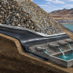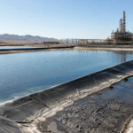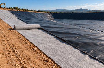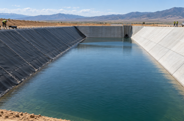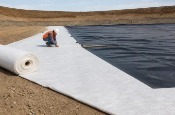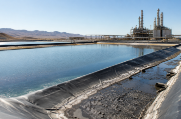
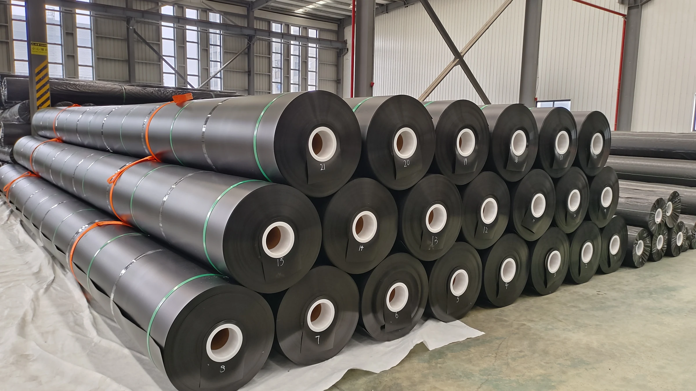
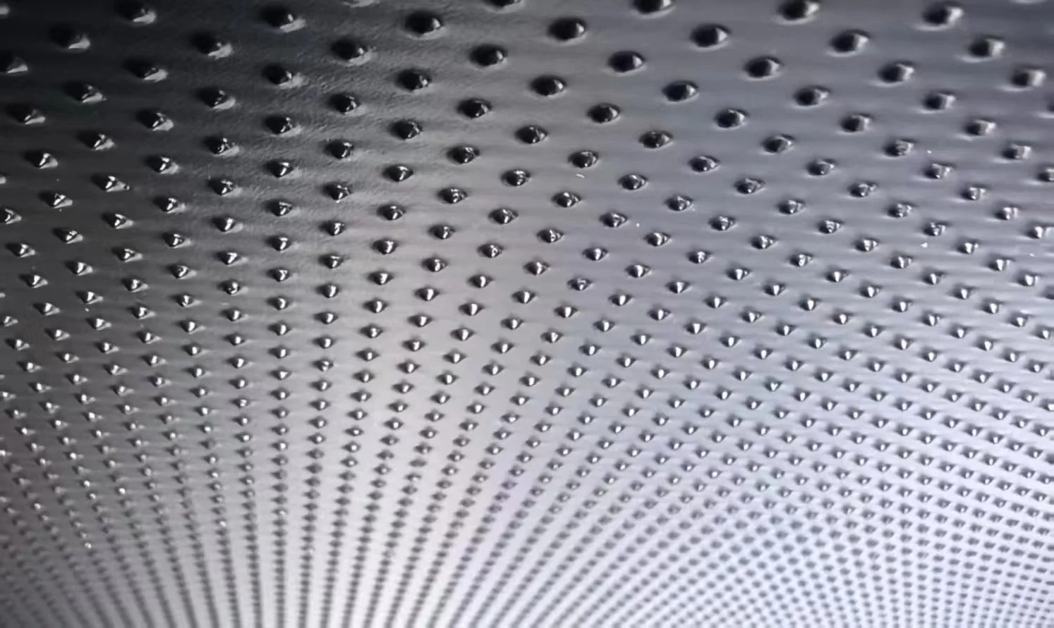
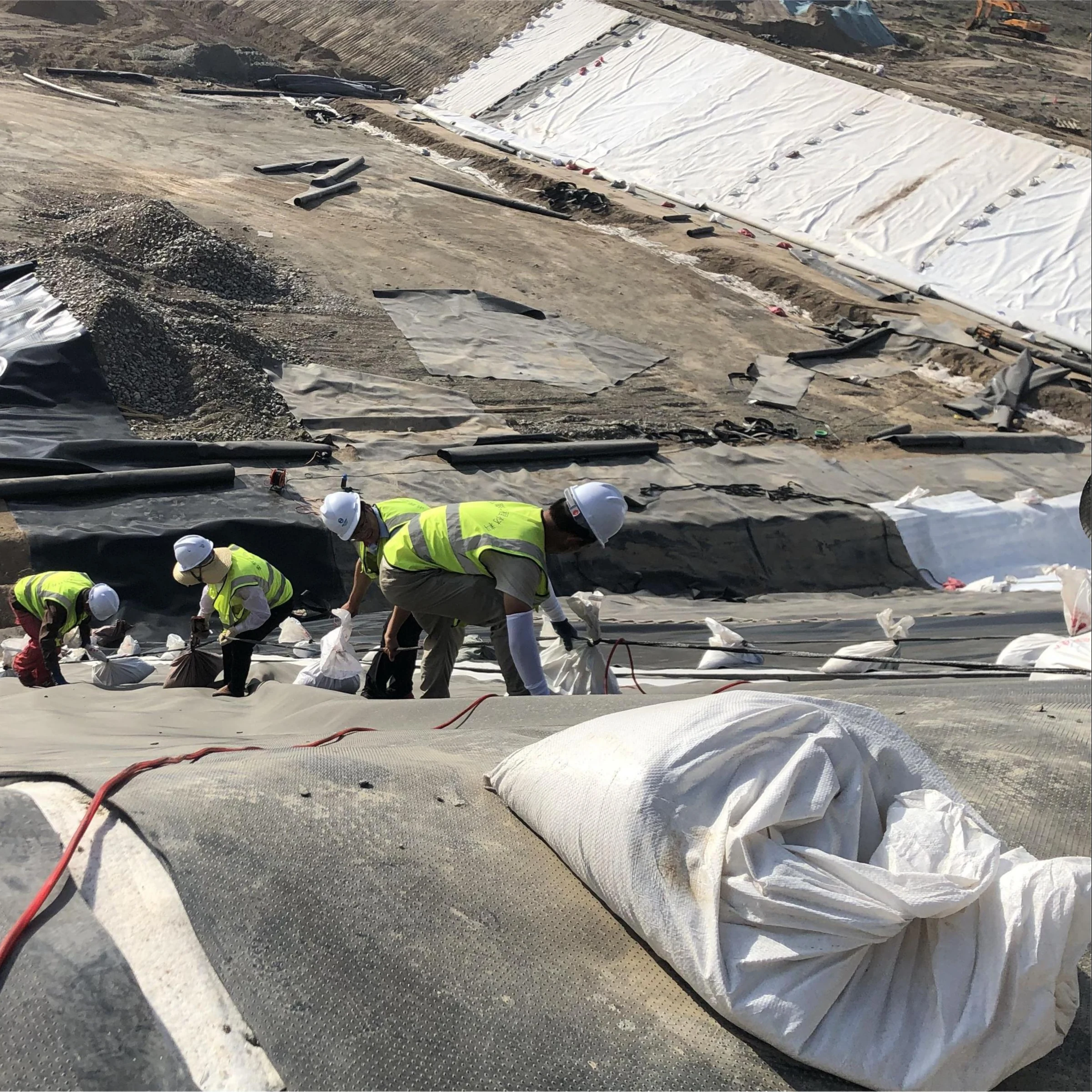
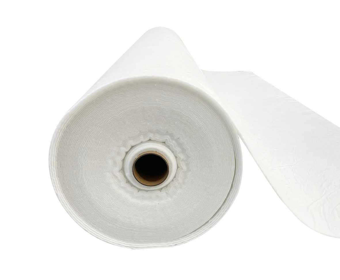

Irrigation canals are the lifeline of agricultural water, but earthen canals have water seepage losses as high as 30%-50%. According to FAO statistics, approximately 60% of global agricultural irrigation water withdrawals are lost to seepage during transmission. Concrete lining can reduce seepage loss rate from 40% to below 5%, and water use efficiency increases from 0.55 to above 0.90.
Flow Velocity
Safe Flow Velocity
Safe flow velocity is the primary factor in determining canal lining design parameters. When water flow velocity is too low, sediment particles carried in the water will settle and accumulate at the canal bottom. Plant roots from organic matter decomposition in the silt will penetrate the concrete slab joints, causing lining upheaval; when flow velocity is too high, the scouring force of water on the concrete surface exceeds the material’s anti-scouring limit, causing surface mortar peeling, aggregate exposure, and wear failure. During design, an optimal range must be found between preventing sedimentation and resisting scouring.
According to the US Bureau of Reclamation (USBR) canal design manual, the safe flow velocity limits for different lining materials are as follows: bare earth canal is 0.3-0.9m/s; compacted clay lining is 0.9-1.5m/s; plain concrete lining (C20) is 1.5-4.5m/s; reinforced concrete lining (C30) is 4.5-6.0m/s; gabion paving is 2.5-4.0m/s; steel plate lining can reach 8-12m/s. For sediment-laden flow (sediment concentration > 5kg/m³), the above safe flow velocity limits should be multiplied by a 0.8 reduction factor. For mountain canals with steep slopes, if the design flow velocity exceeds 6m/s, drop stilling basins or steel plate lining solutions must be adopted.
In actual operation, flow meters (propeller or electromagnetic type) should be installed at key canal sections (inlet, outlet, bends, steep slope section starts) to measure flow velocity distribution quarterly. When measured flow velocity exceeds the safe limit, scheduling plans should be adjusted or energy dissipation measures taken promptly to prevent high-speed water flow from causing impact damage to the lining.
Canal Slope Control
Canal slope (longitudinal slope) is the direct hydraulic factor determining flow velocity—the greater the slope, the greater the gravitational component of water flow, and the higher the flow velocity. The core goal of slope control is to ensure that actual operating flow velocity remains within the safe range (between non-scouring and non-silting velocities). Canal slope measurement method: install leveling points every 50m along the canal bottom (compressed to 20m for important canal sections), measure elevations of each point, and calculate the ratio of elevation difference to horizontal distance between adjacent leveling points, which is the longitudinal slope of that section.
Slope deviation management of lined canals is the core work of routine maintenance. When measured longitudinal slope deviates from the design slope by more than ±15%, the cause should be analyzed immediately—canal bottom sedimentation will make the actual longitudinal slope gentler; canal foundation settlement may make the local longitudinal slope steeper or gentler; side slope collapse causing canal width narrowing will increase local flow velocity and accelerate scouring damage. Maintenance personnel should record canal bottom elevation, canal water level, and canal top elevation at each measurement point simultaneously, and draw canal longitudinal profile diagrams to compare with completion archives. Routine inspection cycle: once per quarter for large main canals, once every six months for branch canals, and once per year for minor canals. When slope abnormality occurs, canal bottom sedimentation (mechanical dredging) or canal foundation settlement (foundation reinforcement) should be prioritized over simply adjusting longitudinal slope parameters.
Longitudinal undulations in the canal alignment also affect flow velocity distribution—local depression sections easily form dead water zones and sedimentation, which should be discovered through regular measurements and corrected through dredging or local lining thickening measures to restore normal longitudinal slope.
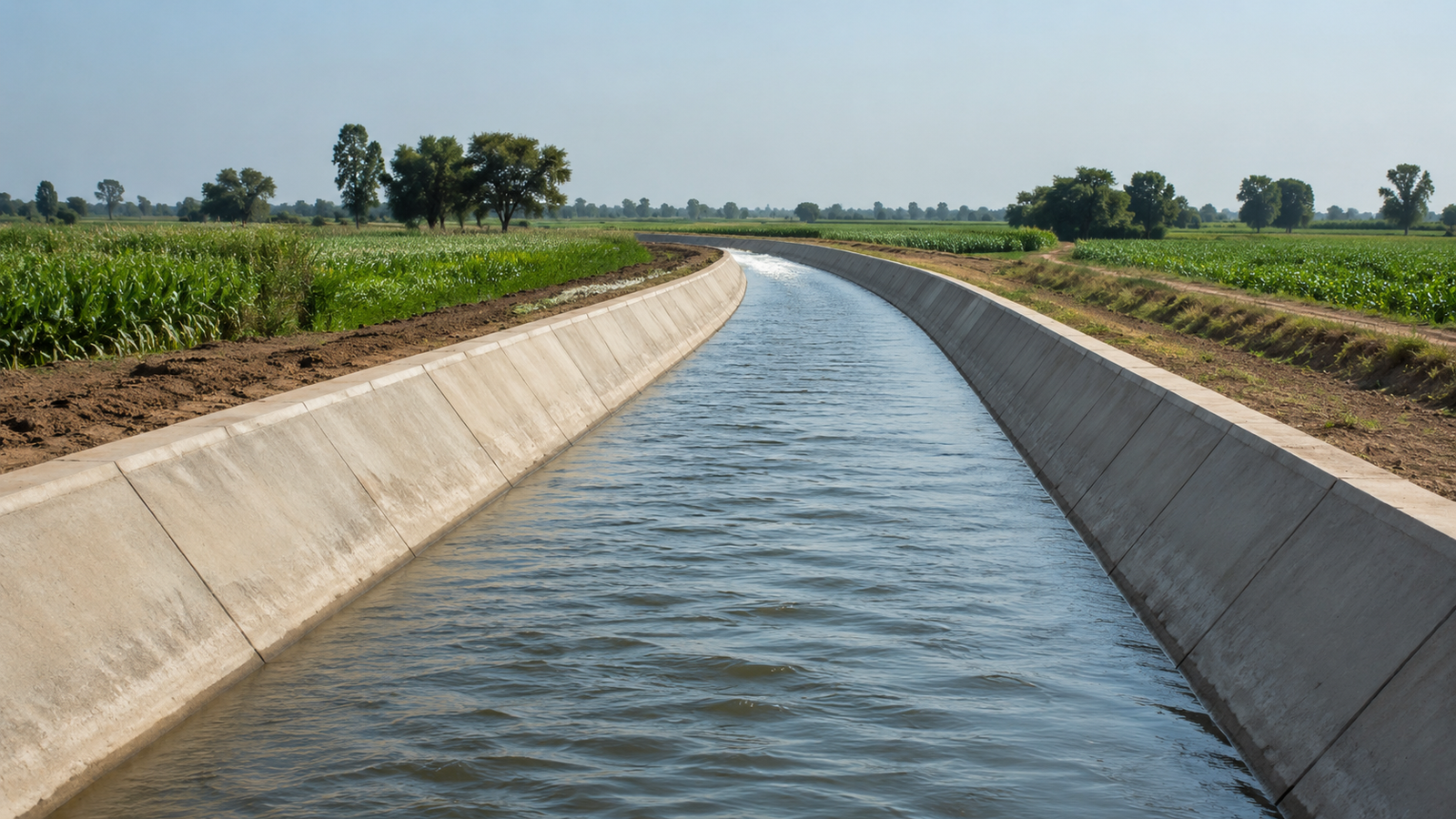
Reducing Water Losses
Direct water losses caused by canal seepage are the core source of irrigation efficiency losses, but the indirect effects of seepage are equally important. The movement of seepage water through the canal foundation soil produces two directional destructive effects: first, seepage water forming upward flow in the canal foundation moistens the lower part of the soil slope, reducing the shear strength of side slope soil and inducing shallow landslides; second, seepage water carries fine soil particles away, forming cavities under the lining slabs. Water accumulating in cavities and freezing expansion produces volumetric forces that can directly uplift concrete slabs, causing slab misalignment and fractures.
Engineering measures for reducing water losses are divided into three levels: Level One is reducing seepage volume—through concrete lining, the canal seepage coefficient (K value) is reduced from the order of 1×10⁻⁵m/s for earthen canals to the order of 1×10⁻¹¹m/s, which is the most fundamental means of reducing water losses; Level Two is drainage and seepage diversion—a graded sand and gravel drainage layer and longitudinal drainage pipes (UPVC pipes, diameter 50-100mm) are installed under the lining slabs to guide seepage water to collection wells outside the canal embankment for discharge, preventing seepage water from accumulating under the slabs and generating uplift pressure; Level Three is seepage monitoring—osmometers and water level observation holes are buried under the lining slabs to regularly monitor the seepage water head under the slabs and changes in foundation soil moisture content, providing timely warnings and locating seepage points when seepage volume shows significant increase.
Erosion Control
Preventing Soil Loss
Unlined or poorly lined channels face soil loss mainly from three hydraulic processes: overland sheet erosion – rainwater collects on the slope surface forming concentrated flows that erode topsoil into rills; bed load erosion – sand and gravel carried in the water moves along the bottom, abrading the channel bed; wave scouring – repeated wave impact on the toe of the slope. These three processes operate with different intensities at different locations, collectively threatening the structural stability of the channel.
Measures to prevent soil loss are divided into engineering measures and vegetative measures. Engineering measures: install collection channels at the top of the embankment (width ≥400mm, depth ≥200mm, cast-in-place C15 concrete) to direct slope runoff to the external drainage system; install erosion protection aprons at erosion-prone areas such as the outer bank of bends and downstream of drop structures (gabion stone cages or geotextile sandbags, depth ≥500mm). Vegetative measures: plant shallow-rooted, dense grass species on the embankment slopes (bermudagrass, bahiagrass), whose root systems interlock with the surface soil to form a reinforced layer, increasing surface soil erosion resistance by 5-8 times, while vegetation stems and leaves slow slope runoff velocity by 30%-50%. Slope vegetation should be locally adapted species, planted at a density of no less than 20 plants per square meter, and regularly pruned after establishment to prevent roots from penetrating too deeply into liner joints.
For slopes with existing shallow gully erosion, engineering repair should be performed first (cleaning erosion channels, backfilling and compacting surface soil), then geocomposite mattress protection should be installed, followed by vegetation planting to prevent recurring erosion.
Protecting Channel Banks
Channel banks are the first line of defense against slope instability and surface water intrusion. Main failure modes of banks include: slope collapse caused by toe erosion, internal erosion (piping) caused by seepage, and erosion damage to the crest and slopes from slope runoff during heavy rainstorms. Bank protection requires both structural reinforcement and drainage control.
Structural reinforcement measures: install 3D geogrid mattress or interlocking block revetment on the outer slope (landside slope), thickness 80-150mm, allowing vegetation penetration to form composite slope protection; install concrete crest coping at the embankment top (width ≥500mm, thickness ≥100mm) to prevent rainwater infiltration into the embankment; install gabion retaining walls or riprap sills at the slope toe (particle size 100-300mm) to resist lateral earth pressure from toe erosion. Drainage control measures: install drainage blanket drains behind the embankment (gravel fill with perforated UPVC drain pipe at the bottom) to keep the groundwater level below the embankment foundation to prevent piping at seepage exit points; install transverse collection channels every 20-30m along the slope to systematically direct slope runoff to the toe drainage channel.
For embankment sections with piping, immediately lower the channel water level and seal the outlet (sandbag filter containment), while placing filter material (graded sand and gravel) at the landside slope toe to prevent the situation from worsening; if necessary, grout reinforcement of the embankment soil should be employed. After the piping emergency is resolved, a comprehensive inspection of the embankment should be conducted to identify other potential seepage pathways.
Preventing Bottom Scour
Bottom scour in channels is concentrated at four types of special locations: flow diffusion sections at the inlet pool (upstream of gates) and outlet pool (downstream of gates), hydraulic jump energy dissipation sections, the inner bank bottom of bends where circulation is strong, and the downstream end of steep slopes. Flow time-averaged velocity and turbulence intensity at these locations are significantly higher than in straight uniform flow sections, and the shear stress on the channel bottom can exceed the soil’s critical entrainment shear stress.
There are four main engineering methods to prevent bottom scour: increasing lining thickness – increasing concrete slab thickness from the standard 100mm to 150-200mm at erosion-prone locations; installing anti-scour ribs – casting concrete rib strips across the channel bottom perpendicular to flow direction at 1.5-2.0m intervals (height 100-150mm) to form a grid-like energy dissipation structure; roughness strip energy dissipation – embedding strip-type roughness elements (10mm×50mm cross-section) in the channel bottom to increase near-wall turbulence resistance and reduce bottom flow velocity; flexible erosion protection mattress – for steep slope sections with very high flow velocities (6-10m/s), covering the channel bottom with 3D geogrid mattress (Erosion Control Blanket) or interlocking concrete blocks, allowing vegetation penetration to form a composite protection layer.
For channel bottoms with existing local scour, the scour pits should be promptly filled (graded sand and gravel, compacted), then a C25 concrete leveling layer should be installed, followed by permanent protection with anti-scour ribs or geogrid mattress to prevent the scour area from expanding. After repair, a staff gauge should be installed upstream of the repaired area to monitor whether the flow pattern has returned to normal.
Concrete Protective Lining
Optimal Lining Types
The selection of concrete lining types should comprehensively consider channel size, hydraulic conditions, geological conditions, and investment budget. The applicable scenarios and performance characteristics vary significantly among different lining types. Incorrect selection can lead to premature lining failure or investment waste.
Based on GB 50288 “Code for Design of Irrigation and Drainage Engineering” and USBR manual, the recommended applications for various linings are as follows: 60-80mm plain concrete is suitable for distributary channels (bottom width <2m, water depth <1m) and other small channels, with simple construction and lowest cost; 80-100mm plain concrete or 80mm reinforced concrete is suitable for farm channels (bottom width 2-5m, water depth 1-1.5m); 100-150mm reinforced concrete is suitable for branch channels (bottom width 5-15m, water depth 1.5-2.5m), with reinforcement ratio not less than 0.3%; 150-200mm reinforced concrete + gravel cushion is suitable for main channels (bottom width >15m, water depth >2.5m), with the cushion beneath the slab serving as both drainage and insulation (in frozen soil areas, XPS insulation board may be used instead). For concave banks at bends with high wear risk, steel fiber reinforced concrete (RPC, with wear resistance 3-5 times that of ordinary concrete) is recommended.
During type selection, base soil conditions should also be considered: in collapsible loess areas, reinforced concrete should be preferred with additional deformation joints; in expansive soil areas, deformation joint spacing should be densified and flexible sealing materials should be selected; in areas with seismic fortification intensity ≥7, slip-form construction technology should be adopted to reduce construction joint quantity and improve integrity. Scientific type selection based on the above factors is a prerequisite for ensuring long-term safe operation of the lining.
Lining Joint Sealing
Joints in concrete-lined channels are the weakest link in the entire seepage prevention system. Joints between lining slabs need to be filled with sealing materials to accommodate displacement between slabs caused by concrete thermal expansion and contraction and uneven foundation settlement. Joint seal failure is the main cause of seepage in lined channels—the seepage volume at joints can be 10-50 times that of intact concrete slabs of the same area.
Joint seal inspection contents include: sealant integrity—checking for aging, cracking, detachment, dissolution, and other damage; joint width—measuring actual width with a steel ruler, comparing with design width to determine if it exceeds the allowable displacement of sealing material; waterstop—for deformation joints with PVC waterstops, checking if the waterstop is broken or detached. Inspection frequency: once before the water passage season (after spring thaw) and once after (before autumn water shutdown). When seal failure is found: cracks with width <5mm can be filled with the same type of sealant; when width >5mm or waterstop is broken, the original material must be removed and reconstructed, with the base surface extended 50mm on each side ground flat and dry before applying sealing material.
Commonly used sealing materials include polyurethane sealant (PU, suitable for areas with large temperature variations, elastic recovery rate >80%), silicone sealant (excellent anti-aging performance but higher price), and rubber swelling waterstop (with water swelling rate of 200%-300%, suitable for deformation joints).
Preventing Concrete Cracking
Concrete cracking is the most common damage form in lined channels. The occurrence of cracks not only destroys the integrity of concrete but also provides pathways for water and aggressive media to enter, accelerating steel corrosion and crack propagation. Preventing concrete cracking requires systematic measures from three aspects: design, materials, and construction.
At the design level: for continuous pouring slabs with length exceeding 20m, temperature contraction joints should be set (joint width 10-20mm, spacing not exceeding 15m), filled with polyethylene foam board as isolation layer; mass concrete (slab thickness >150mm) should use low-heat cement (slag cement or fly ash cement) to reduce hydration heat temperature rise; in frozen soil areas, insulation layer (XPS board, thermal conductivity 0.028W/m·K) should be set under the lining slab to reduce frost heave uplift force on the concrete slab. At the material level: water-cement ratio should be controlled below 0.5, with slump 30-50mm; add high-quality fly ash (replacement rate 15%-20%) or silica fume (replacement rate 8%-10%) to improve concrete crack resistance and durability; coarse aggregate should use continuous graded crushed stone with maximum particle size not exceeding 1/3 of slab thickness. At the construction level: strictly control concrete placing temperature (not exceeding 30°C in summer, not below 5°C in winter); after pouring, promptly cover for thermal insulation and moist curing, with curing time not less than 14 days; formwork removal time should comply with GB 50666 provisions, and premature removal causing edge damage should be avoided.
The long-term performance of channel concrete lining depends on three key factors: the rationality of design type selection, the controllability of construction quality, and the timeliness of operation and maintenance.