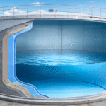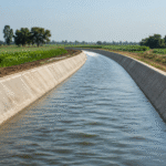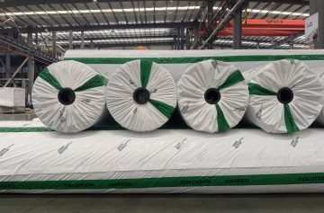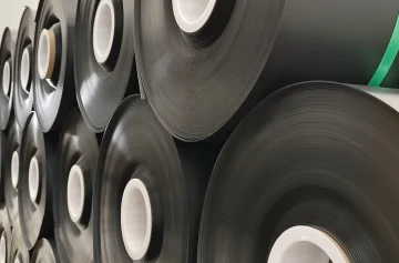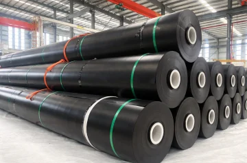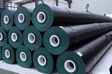
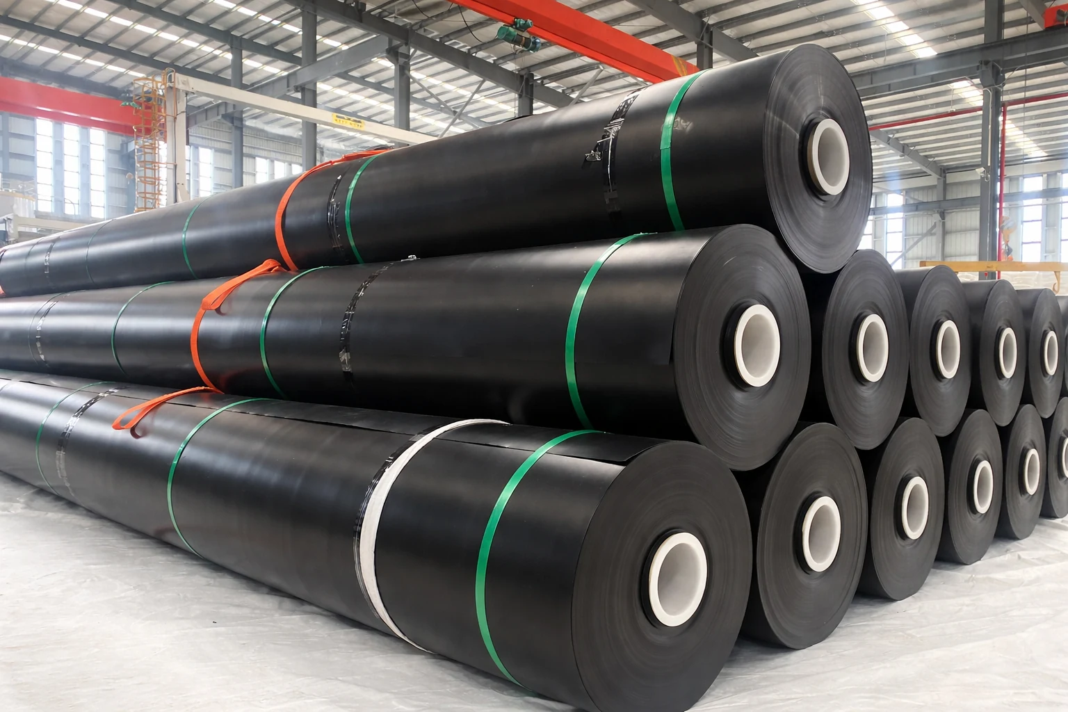
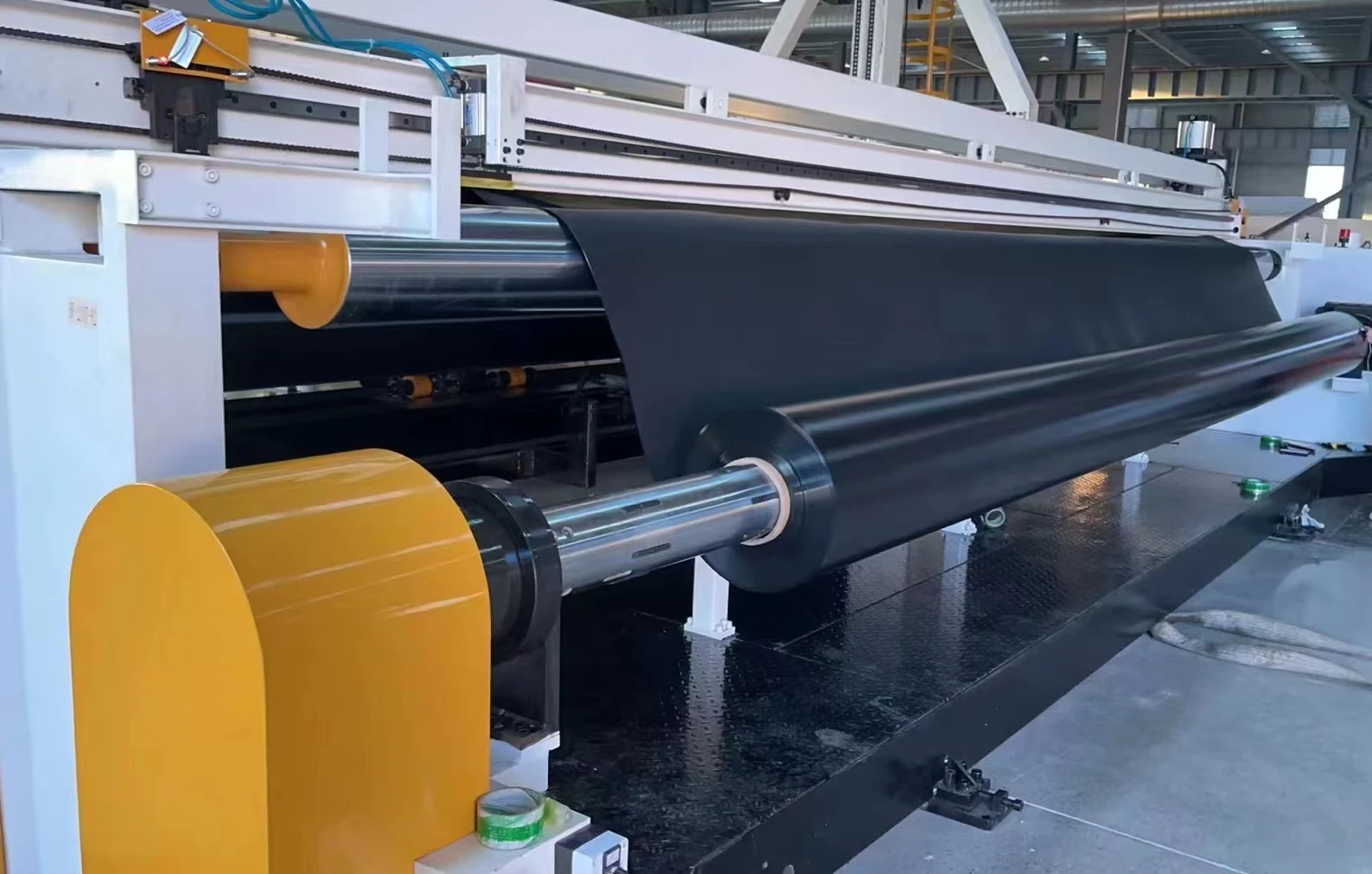
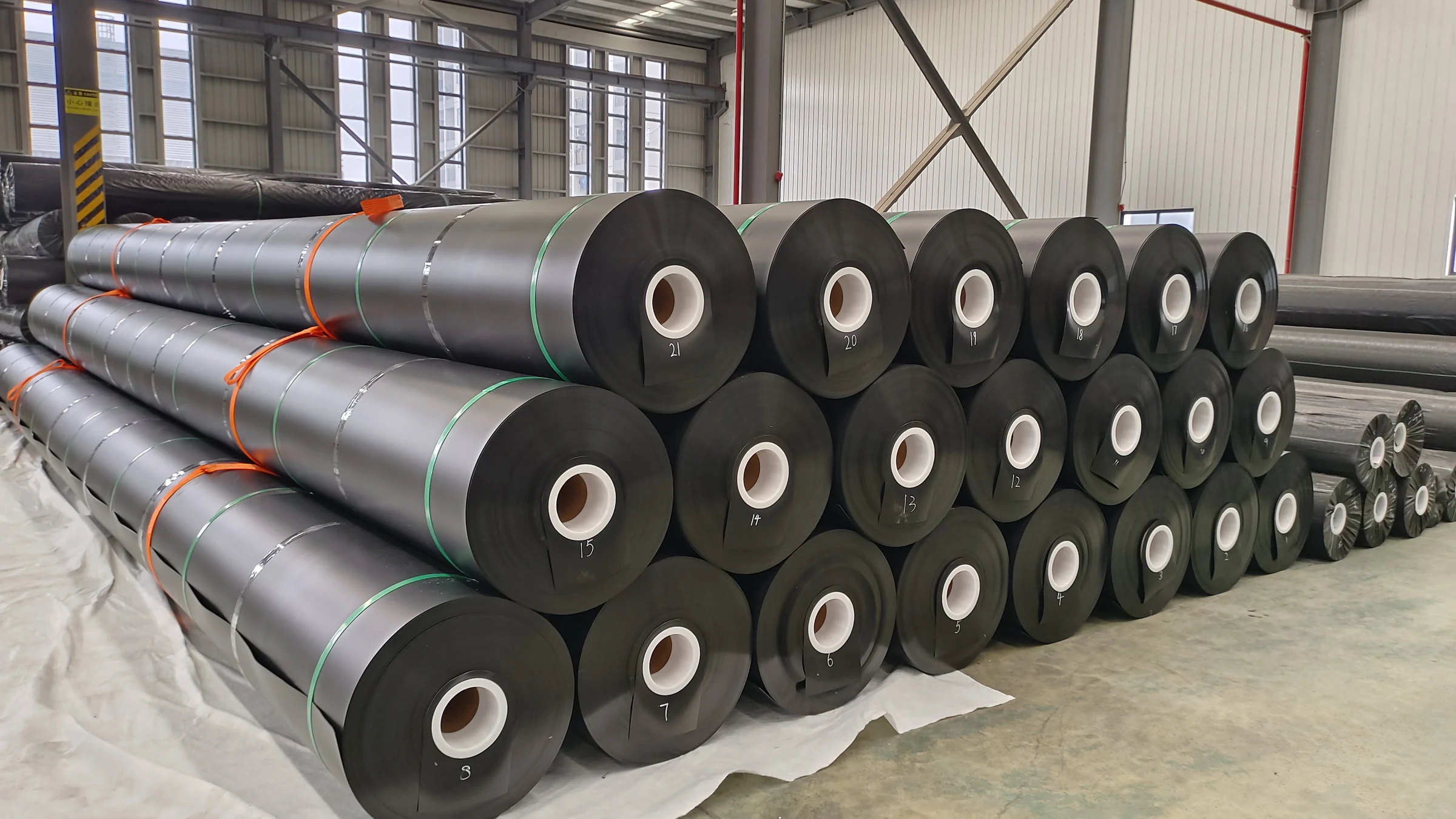
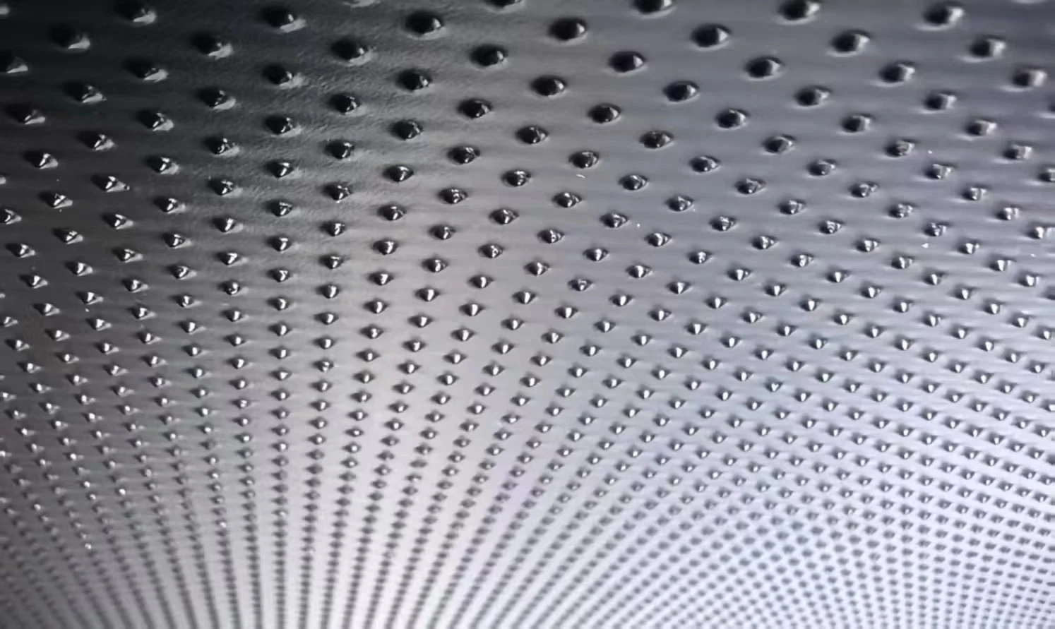
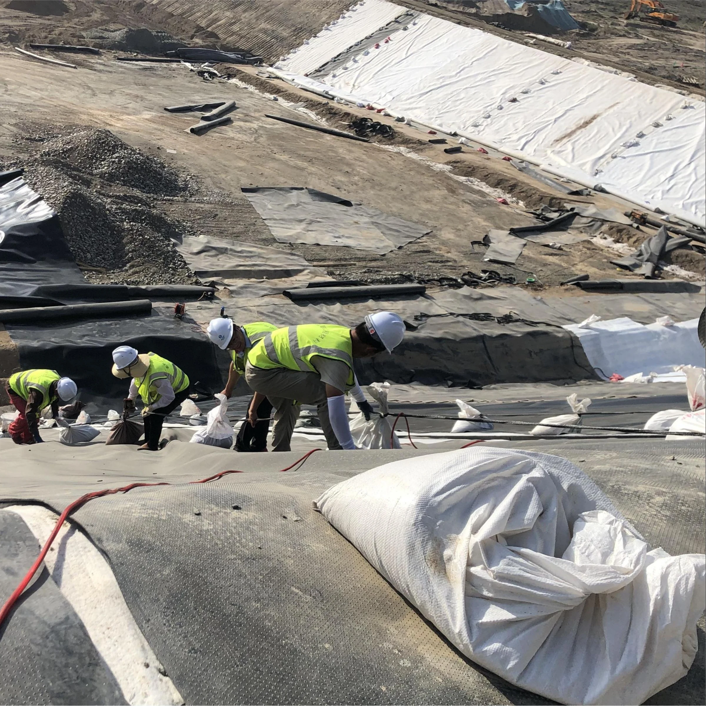
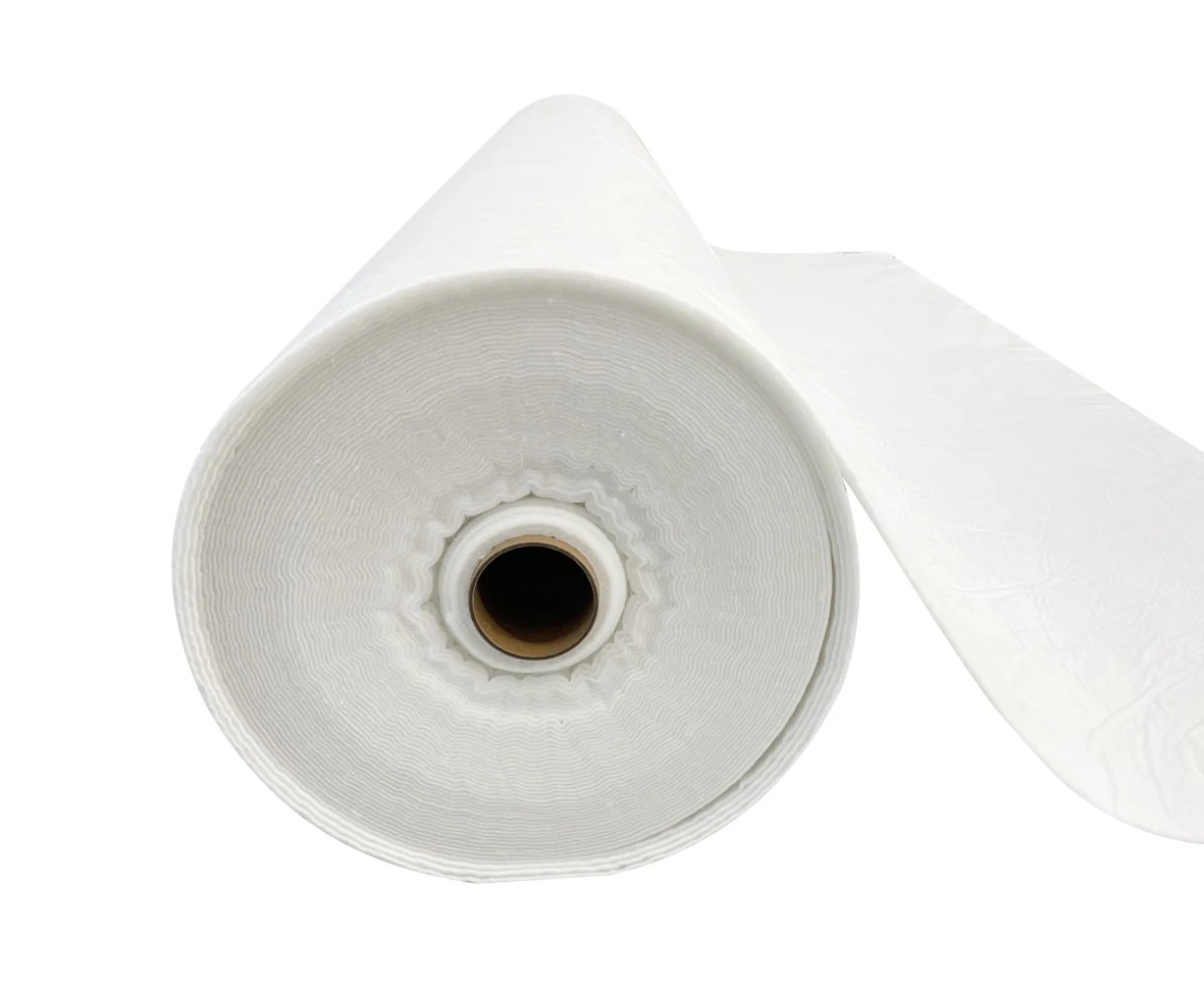

A heap leach pad liner must be selected as part of the complete chemical, geotechnical and solution-management system. HDPE thickness alone does not establish suitability. The design also needs representative solution chemistry, loading and settlement analysis, protection against local damage, suitable interfaces, drainage capacity and a verifiable construction-quality plan.
Gold cyanidation and acid-based copper leaching involve different process solutions. Keep those design cases separate. Confirm the actual reagent composition and operating envelope with the metallurgical and process-safety team before evaluating a liner material.
Chemical resistance: separate alkaline cyanide from acid leaching
Cyanide gold-leaching solution should not be described as operating at pH 1–3. Acidification shifts free cyanide toward volatile, highly toxic hydrogen cyanide. The International Cyanide Management Institute explains that HCN and CN⁻ are approximately balanced around pH 9.3–9.5; at pH 11, more than 99% is in the CN⁻ form. These figures explain chemical speciation, not a complete operating procedure. A site must establish its own controlled operating conditions and monitoring requirements.
Acid-based copper leaching presents a different compatibility question. Record acid concentration, other dissolved species, oxidants, temperature and exposure time rather than reducing the liquid to a pH value. An acid-compatible material is not automatically suitable for every concentration, temperature or mixture.
ASTM D5322-23 provides laboratory immersion procedures; it does not certify all HDPE for a fixed 30-year life or impose a universal 2,000-hour acceptance threshold. ASTM D5747/D5747M-21(2026) provides tests for assessing geomembrane chemical resistance. Specify the exposure liquid, temperature, duration, properties measured and acceptance criteria together.
The EPA 9090A compatibility method is another relevant reference for evaluating effects on liner properties. A successful short immersion test is evidence for those test conditions; projecting years of field performance needs an appropriate aging model and supporting data.
Build a material submittal around traceable evidence
| Design question | Information to request | What the result does not prove alone |
|---|---|---|
| Chemical exposure | Testing of the proposed formulation with representative solutions and temperatures | A universal pH range or unlimited chemical resistance |
| Manufacturing consistency | Product designation, batch traceability, thickness and relevant quality-control results | Suitability of every installation detail |
| Long-term aging | OIT, stress-crack and aging evidence interpreted for the proposed exposure | A guaranteed service life from one index value |
| Protection and loading | System testing with representative foundation, drainage or cover materials and design pressure | A universal safe heap height from a puncture-force result |
| Interface stability | Actual materials tested at relevant normal stress, hydration and displacement | Automatic stability from a textured surface designation |
GRI-GM13 Revision 19 is a manufacturing-quality specification for HDPE geomembranes, with a density threshold of 0.940 g/cm³ and a stated thickness scope of 0.75–3.0 mm. It includes carbon-black, OIT and stress-crack requirements, but is not an approval for every heap leach exposure. Its puncture values vary with thickness and sheet type; it does not impose a single 600 N heap-leach design limit.
For example, comparing 1.5 mm and 2.0 mm candidates is a useful procurement step, but selecting the latter does not establish a fixed 35–40% reduction in field punctures. Request evidence for the proposed construction rather than relying on an unsupported percentage or blanket “virgin resin certification.”
Calculate ore loading with the correct bulk density
For a preliminary vertical overburden estimate, use σᵥ ≈ γH, with bulk unit weight γ in kN/m³ and heap height H in metres. This simplified calculation omits pore-pressure distribution, local contacts, construction loads, foundation geometry and stability effects.
| Explicit assumption | Calculation | Interpretation |
|---|---|---|
| Illustrative bulk unit weight 18–22 kN/m³; height 15 m | 18 × 15 to 22 × 15 = 270–330 kPa | Preliminary uniform stress, not a liner allowable stress |
| Assumed bulk density 2.8 t/m³; height 12 m | 2.8 × 9.81 × 12 = 329.6 kPa, or 0.330 MPa | Valid only if 2.8 t/m³ is the measured bulk density, not mineral particle density |
| Proposed test pressure 50 kPa; assumed unit weight 20 kN/m³ | 50 ÷ 20 = 2.5 m | 50 kPa does not represent a 15 m heap under this assumption |
Measure actual feed and drainage-layer gradations, particle angularity and moisture conditions. The D₈₀ value describes the particle size below which 80% of the sample passes; it does not fully describe the sharpest contacts or maximum particle size. Do not turn D₈₀ above 300 mm into a universal rule for a particular liner thickness and geotextile weight.
Puncture protection: test the assembly, not only the sheet
Index puncture results compare specimens under a defined apparatus. They cannot be read directly as allowable field contact pressures. A result in newtons is a force, while kPa and MPa are pressures; converting between them requires a defined contact area and model. The D4833 index test should not be described as a falling-weight impact test.
ASTM D5514/D5514M-24 includes large-scale hydrostatic puncture procedures using site-specific materials. Its procedures can examine failure as pressure rises or performance at selected pressure, temperature and duration. A designer can use an appropriate performance programme to compare candidate protection systems under representative conditions.
Geotextile mass alone is insufficient. A 600 or 800 g/m² candidate must be assessed with the actual aggregate, geomembrane and loading conditions. Product structure, thickness under load, local strain and construction damage matter. Neither a 600 g/m² minimum nor a claimed 68% reduction in incidents should be presented without project-specific evidence.
Place protection on the side where it addresses the identified damage mechanism and verify its effect on stability and drainage. Protection beneath the membrane does not automatically shield its upper face from drainage aggregate or ore placement. Smooth and textured products also require separate interface and protection assessments; neither surface is universally safer against puncture.
Settlement and stability require a compatible foundation system
Evaluate total settlement, differential settlement, its spatial profile and the resulting strain near seams, penetrations and anchor details. A 150 mm movement spread across a broad smooth depression is different from the same displacement across a short sharp transition. A fixed allowable settlement in millimetres is therefore not enough to select the liner system.
Foundation treatment should follow the site investigation. A low SPT value does not automatically justify six months of wick-drain preloading. Drainage path, soil compressibility, loading sequence, groundwater and available time determine the appropriate treatment and verification.
GCLs are barriers, not universal settlement cushions. If specified, check chemical compatibility, hydration and both internal and interface shear using appropriate testing such as ASTM D6243/D6243M-26. Bentonite swelling does not guarantee healing of every defect or make controlled sliding a valid design assumption. Numerical analysis may be useful, but the level of analysis must be justified by the geometry and risk.
Solution recovery: distinguish collection from metallurgical recovery
A contained and adequately drained pad helps recover process solution. It does not set the fraction of metal dissolved from the ore. A liner slope or drainage texture cannot by itself guarantee a 5–8% improvement in gold or copper recovery.
Locate process-solution collection above the primary barrier according to the approved cross-section. A drainage layer beneath that barrier may serve leak detection or foundation drainage; it is not interchangeable with the primary collection system. Separate and identify the destinations of those flows.
Develop the operating water balance for irrigation, precipitation, runoff, evaporation, drain-down, recirculation and credible equipment outages. Check solution-storage capacity and freeboard against the governing design events and operating plan. Neither a universal 60% normal pond level nor seven days of peak flow is a substitute for that assessment.
As an explicit volume example, 50 mm of rainfall over 10 ha corresponds to 0.05 m × 100,000 m² = 5,000 m³ of gross precipitation. It is not automatically the required pond volume: contributing catchments, runoff, retained water, simultaneous process flows and drain-down must be evaluated separately.
Size collection pipes and drainage media for the relevant load, hydraulic gradient and potential clogging. Manning roughness comparisons are meaningful only for an appropriate open-channel model with its other variables defined; they should not be used alone to predict flow through a loaded ore heap or drainage blanket. Establish cleaning provisions and inspection triggers for the actual system.
Quality assurance and leak detection
Keep material acceptance, panel installation, seam testing, repair records and protection-layer placement within one CQA programme. Define test methods for the actual material and seam type. A general “85% of parent strength” rule is not an adequate substitute for the specified peel, shear and failure-mode criteria.
Select electrical leak location for the installed cross-section and construction stage. An exposed-liner spark or arc procedure cannot simply be repeated through a loaded heap. See the ELL method guide for distinctions between conductive-backed sheet, exposed and covered surveys. Report any areas that cannot be surveyed rather than treating incomplete coverage as proof of integrity.
Operational leak detection needs an identified collection or monitoring arrangement, performance criteria and response plan. Do not equate an electrical signal-detection threshold with a universally measurable liquid leakage rate such as 0.05 L/ha/day. Periodic inspection cannot establish that a liner has zero permeability or zero future leakage.
Information to include in a heap leach liner enquiry
- Site location, governing design and permit requirements, and approved liner cross-section.
- Process solution composition, concentration, temperature and expected variations.
- Final and staged heap height, measured bulk unit weight, aggregate properties and foundation conditions.
- Candidate membrane thickness and surface, protection layers, roll dimensions and panel layout.
- Required compatibility, aging, protection, interface and seam-test evidence.
- Construction sequence, inspection access, leak-detection design and document-retention requirements.
For the distinction between manufacturing conformity and project suitability, use the GM13 procurement guide. The responsible engineering team should approve the final specification, using traceable test results and acceptance criteria for the proposed products and installation.