Geotextile filter cloth is used between soil and drainage or protection layers to retain particles while allowing water to pass. In civil engineering, landfill drainage, pond embankments, road subgrades, retaining wall drains, and erosion control works, the fabric must be selected by soil gradation, hydraulic condition, flow demand, installation stress, and long-term clogging risk. A product weight alone is not enough for filter design. Apparent Opening Size, permittivity, water flow rate, puncture resistance, tensile strength, and field contact quality should be reviewed together before installation.
For PET continuous filament non-woven geotextile, filtration performance depends on a three-dimensional pore structure rather than a simple screen opening. This structure can support soil retention, separation, cushioning, and drainage support, but only when the selected fabric is compatible with the base soil and the full drainage system.
AOS Selection
AOS selection defines how the geotextile filter cloth balances soil retention and water passage. In drainage trenches, slope protection, landfill drainage layers, road subgrades, and erosion control works, the Apparent Opening Size should be matched with soil particle distribution, especially D85 and fine content. A smaller opening improves retention of silts and fine sands but can increase clogging risk. A larger opening improves flow but may allow particle migration. For PET continuous filament non-woven geotextile, selection should consider soil gradation, hydraulic gradient, expected sediment load, installation contact, and long-term clogging resistance, not only the nominal opening value.
Matching AOS to Soil Gradation
AOS should be selected after reviewing the soil gradation curve, not by choosing a geotextile weight alone. The opening size must be small enough to retain the base soil while still allowing water to move through the fabric. Clean sand, silty sand, clayey soil, and gap-graded fill can behave differently under the same geotextile.
| Soil Parameter | What It Indicates | Why It Affects AOS Selection |
|---|---|---|
| D85 | Particle size at which 85% of soil is finer | Often compared with geotextile opening size for retention review |
| D15 | Fine-side particle distribution | Helps estimate drainage and particle movement behavior |
| Percent passing No. 200 sieve | Silt and clay content | Higher fine content increases clogging risk |
| Uniformity coefficient | Gradation spread | Poorly graded or gap-graded soils need closer filter review |
| Plasticity index | Clay behavior and cohesion | Cohesive fines can blind the geotextile surface |
A coarse gravel drainage interface may allow a larger AOS because the retained soil particles are larger and less mobile. A fine sandy subgrade, silt-rich slope, landfill drainage interface, or pond embankment usually requires a smaller AOS and closer evaluation of clogging potential. The same fabric can perform differently when installed against compacted sand, loose fill, or clayey soil.
- Use soil gradation data from representative samples, not only visual soil descriptions.
- Review both soil retention and water flow before selecting the fabric.
- Check whether the geotextile will contact compacted soil, loose fill, drainage aggregate, or riprap.
- Consider whether the project has continuous seepage, seasonal flow, or short stormwater loading.
- Use a protection layer when angular stone, construction traffic, or high puncture stress is expected.
Apparent Opening Size Test Reference
Apparent Opening Size is commonly evaluated by dry sieving methods such as ASTM D4751. The test helps identify the approximate opening size of a geotextile by determining the glass bead size retained or passed through the material. AOS is often reported as an O95 value. A lower O95 indicates smaller openings, while a higher O95 indicates larger openings.
The test value is useful for product comparison, but it should not be treated as the full filter design. Laboratory AOS is measured under controlled conditions. Field conditions include soil pressure, compaction, sediment loading, biological activity, chemical exposure, and installation damage.
| Property | Common Test Reference | Design Use |
|---|---|---|
| Apparent Opening Size | ASTM D4751 | Soil retention and particle migration control |
| Permittivity | ASTM D4491 | Cross-plane water flow through the geotextile |
| Water flow rate | ASTM D4491 | Flow comparison under standard test conditions |
| Grab tensile strength | ASTM D4632 | Handling and installation resistance |
| Puncture resistance | ASTM D6241 | Resistance against aggregate and subgrade damage |
| Mass per unit area | ASTM D5261 | General material comparison, not a substitute for filter design |
For procurement and specification review, the data sheet should show the tested AOS value, test method, tolerance range, and related hydraulic properties. If a supplier only provides fabric weight without AOS and permittivity data, the specification is incomplete for filter applications.
- Confirm that AOS is listed with a recognized test method.
- Compare AOS with the project soil gradation curve.
- Check permittivity or flow rate to avoid selecting a fabric that retains soil but restricts drainage.
- Review puncture resistance when angular aggregate or riprap will be placed over the fabric.
- Confirm roll handling, overlap, and seam requirements before installation.
Non-Woven Structure and Pore Distribution
PET continuous filament non-woven geotextile does not work like a woven screen with uniform square openings. Its pore structure is three-dimensional, with fibers forming irregular flow paths through the fabric thickness. This structure can support filtration stability because particles are not retained only at a single surface layer.
| Structural Factor | Engineering Effect |
|---|---|
| Fiber diameter | Influences pore size and filtration behavior |
| Fabric thickness | Provides depth filtration and cushioning |
| Needle-punched density | Affects pore distribution and mechanical strength |
| Mass per unit area | Supports product comparison but does not define AOS alone |
| Compression under load | Can reduce pore space and change flow behavior |
A thicker non-woven geotextile may provide better cushioning for geomembrane protection, but filtration use still requires proper AOS and flow data. A high-mass fabric with unsuitable pore distribution can still clog or allow fines to migrate if the soil condition is not matched.
- Prepare the subgrade to remove sharp stones, roots, debris, and soft pockets.
- Place the geotextile without excessive tension or large wrinkles.
- Use adequate overlap based on soil condition, slope angle, and expected flow direction.
- Prevent aggregate dumping from excessive height, which can damage the fabric.
- Inspect for tears, punctures, displaced overlaps, and clogged surface areas before cover material is completed.
Soil Retention
Soil retention is the filter function that prevents base soil from moving into drainage aggregate, riprap voids, collection pipes, or protection layers while still allowing seepage water to pass. For geotextile filter cloth, retention should be checked against soil gradation, especially D85, fine content, plasticity, and expected hydraulic gradient. In civil drainage, slope protection, landfill drainage layers, road subgrades, and pond embankments, poor retention can cause soil piping, surface settlement, outlet sediment, and loss of support. Selection should compare AOS/O95, permittivity, puncture resistance, overlap layout, and soil contact quality before installation.
Fine Particle Migration Control
Fine particle migration happens when seepage water carries sand, silt, or clay-sized particles from the base soil into the drainage layer or through the geotextile opening structure. The result can be soil loss behind the filter, reduced bearing support, cloudy discharge, blocked drainage outlets, and localized settlement.
| Control Factor | Engineering Requirement | Field Risk if Ignored |
|---|---|---|
| Soil gradation | Review D85, D50, fine content, and plasticity | Wrong AOS selection may allow soil piping |
| Hydraulic condition | Check seepage direction, gradient, and flow duration | High seepage force may move fine particles faster |
| Geotextile contact | Keep fabric flat and in contact with base soil | Gaps allow soil to move under the fabric |
A smaller opening can improve retention, but if the soil has high clay or silt content, surface blinding can reduce drainage capacity. A larger opening can improve flow, but it may allow fine sand or non-cohesive silt to migrate under sustained seepage. Correct selection must balance soil retention and hydraulic capacity.
- Compare D85 and O95 instead of relying only on fabric weight.
- Review the percentage passing the No. 200 sieve to estimate fine content.
- Check whether upward seepage, slope seepage, or outlet flow increases migration risk.
- Review soil cohesion because clean sand, silty sand, clayey sand, and plastic clay behave differently.
- Use adequate puncture resistance when angular drainage aggregate is placed over the filter cloth.
For retaining wall drainage, road edge drains, landfill drainage layers, and slope erosion control, early warning signs include sediment at drainage outlets, visible soil loss near edges, settlement above the filter zone, and water moving beneath the geotextile instead of through it.
Filter Compatibility with Base Soil
Filter compatibility means the geotextile is matched to the actual base soil condition. A PET continuous filament non-woven geotextile can provide filtration, separation, drainage support, and cushioning, but it must still be selected according to the soil it contacts. One fabric may work well against compacted sand and perform poorly against soft silt or gap-graded fill.
| Base Soil Condition | Retention Concern | Geotextile Selection Focus |
|---|---|---|
| Clean sand | Particle loss under seepage | AOS matched to D85 and flow direction |
| Silty sand | Fine migration and clogging | AOS, permittivity, and sediment loading |
| Clayey soil | Surface blinding and low drainage | Permittivity and contact stability |
| Gap-graded soil | Loss of finer fraction | Gradation curve review and retention testing |
| Weak subgrade | Deformation and pumping | Separation, tensile strength, and puncture resistance |
The design review should start with soil classification and gradation data. Visual descriptions such as sandy soil or clayey soil are not enough for filter selection. Field samples should represent the installed area, especially in long slopes, road sections, drainage trenches, and pond embankments where soil conditions may vary.
- For road and rail subgrades, review separation and retention under repeated loading.
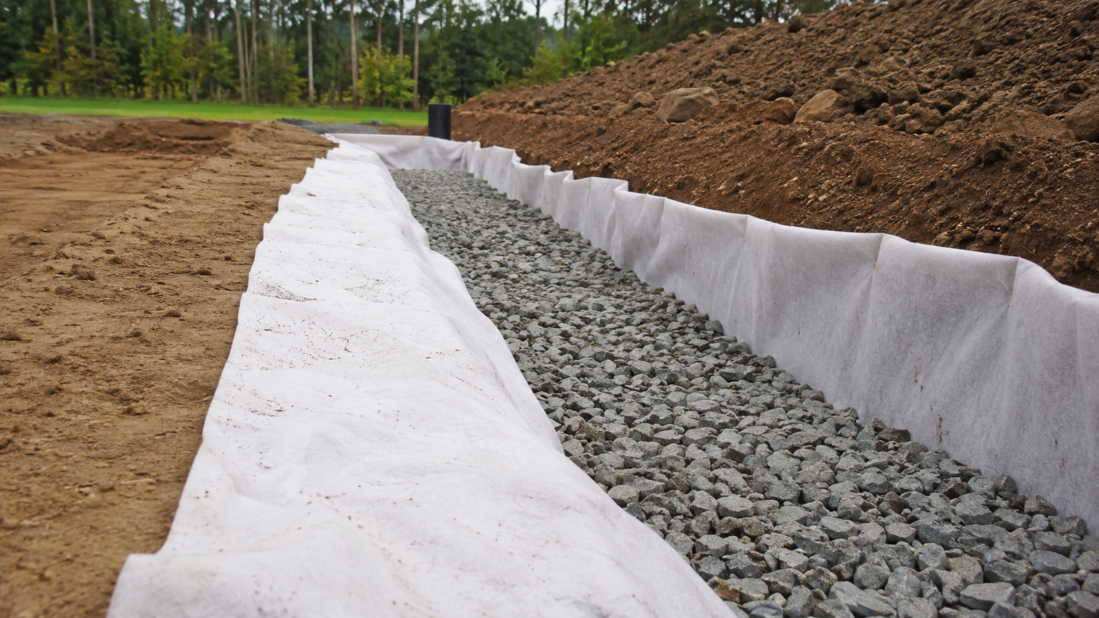
- For drainage trenches, retain soil while allowing water into aggregate or perforated pipe bedding.
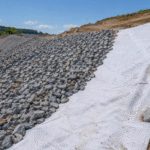
- For slope protection, match overlap orientation with expected flow direction.
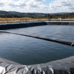
- For landfill and pond systems, review filtration, drainage, and puncture protection together.
- For riprap underlayment, check puncture resistance and retention under runoff or intermittent flow.
A practical specification should include tested AOS, permittivity, water flow rate, tensile strength, puncture resistance, roll dimensions, overlap requirements, and installation damage control. Without these details, the buyer cannot judge whether the filter cloth is suitable for the base soil.
Contact Quality Between Soil and Geotextile
Even a correctly selected geotextile can fail to retain soil if it is poorly installed. Soil retention depends on continuous contact between the base soil and the filter cloth. Voids, wrinkles, bridging, loose folds, and displaced overlaps create paths where water can carry fine particles under the fabric instead of through the pore structure.
| Installation Point | Control Direction | Retention Risk if Poor |
|---|---|---|
| Subgrade preparation | Smooth surface, no sharp debris, no large voids | Fabric bridging and underflow |
| Wrinkle control | Lay flat without excessive tension | Soil movement below folds |
| Overlap width | Use project-specified overlap; increase where soil or slope risk is higher | Separation at joints |
| Cover placement | Place aggregate or soil without dragging the fabric | Tears and displaced panels |
| Edge restraint | Secure edges, outlets, and transitions | Water entry below the filter layer |
For many field applications, overlaps are commonly specified in the range of 300–600 mm, with wider overlap or sewn seams considered for weak subgrades, underwater placement, steep slopes, or high-flow zones. The exact value should follow the project specification and site condition.
- Check tears, punctures, burn marks, and damaged roll edges before covering.
- Reject open seams, short overlaps, and misaligned panels before placing aggregate.
- Remove wrinkles large enough to create flow paths.
- Correct soft soil pockets under the fabric.
- Protect exposed geotextile from wind displacement and rainfall before final cover.
- Check sediment flow at drainage outlets after the first significant water loading where accessible.
Flow Capacity
Flow capacity defines whether geotextile filter cloth can pass water fast enough without creating excess pore pressure, soil softening, or drainage backup. For filtration work, cross-plane flow is usually reviewed through permittivity and water flow rate, commonly tested under ASTM D4491. Selection should not rely only on fabric weight or AOS; a fabric that retains soil but restricts seepage can still cause field problems. In drainage trenches, landfill drainage layers, retaining wall backdrains, road subgrades, pond embankments, and slope protection systems, flow capacity must be checked against fine content, hydraulic gradient, expected sediment loading, contact pressure, and long-term clogging risk.
Cross-Plane Water Permeability
Cross-plane water permeability describes how water moves through the thickness of the geotextile, from the soil side to the drainage side. In filter applications, this direction matters more than in-plane drainage because the fabric is often placed between base soil and drainage aggregate, riprap, geocomposite, or perforated pipe bedding.
| Property | Common Test Reference | What It Shows | Design Relevance |
|---|---|---|---|
| Permittivity | ASTM D4491 | Water flow through fabric per unit head | Main indicator for cross-plane flow |
| Water flow rate | ASTM D4491 | Flow under standard laboratory conditions | Useful for comparing products |
| AOS / O95 | ASTM D4751 | Approximate opening size | Must be balanced with flow capacity |
| Thickness | ASTM D5199 | Fabric thickness under pressure | Affects pore volume and cushioning |
| Mass per unit area | ASTM D5261 | Fabric weight class | Not enough for flow design alone |
A high water flow rate on a data sheet does not automatically mean the filter will perform well in the field. Laboratory testing uses clean water and controlled conditions. Site conditions may include suspended fines, compaction pressure, biological growth, chemical exposure, and sediment deposition.
The selected geotextile should usually have higher flow capacity than the surrounding soil so the fabric does not become the limiting drainage layer. If the soil has low permeability, an extremely high-flow geotextile may not improve system performance. If the soil has moderate seepage and the fabric has low permittivity, water can accumulate at the soil-fabric interface.
- Review soil permeability because clean sand, silty sand, and clayey soil drain differently.
- Identify the water source, such as constant seepage, stormwater, wave action, or intermittent pond drawdown.
- Consider contact pressure from aggregate cover, embankment load, or drainage stone.
- Check whether punctures, clogged surfaces, or displaced overlaps could reduce effective flow area.
- Confirm that pipe, outlet, and drainage layer capacity are not lower than the geotextile flow capacity.
Clogging Risk in Fine Soils
Clogging occurs when soil fines, organic particles, precipitates, or biological growth reduce the open pore space of the geotextile. Fine soils are more sensitive because small particles can collect on the fabric surface or inside the fiber structure. This can reduce flow capacity over time, especially under constant seepage or high sediment load.
| Clogging Mechanism | Typical Site Condition | Result |
|---|---|---|
| Surface blinding | Clayey soil or high suspended solids | Water cannot enter the fabric evenly |
| Internal clogging | Fine sand and silt carried into the pore structure | Flow path becomes restricted |
| Biological clogging | Nutrient-rich water, wastewater, or stagnant drainage | Biofilm reduces pore space |
| Chemical precipitation | Mineral-rich seepage or industrial wastewater | Deposits form inside or on the fabric |
| Construction sediment | Dirty aggregate, exposed soil, or runoff before cover | Early-stage flow reduction |
Fine soils need more than a small AOS. If the opening is too small, the surface may blind. If the opening is too large, fine particles may migrate into the drainage layer. The correct selection must balance retention and flow, then be supported by clean installation and controlled cover placement.
- Check the percentage passing the No. 200 sieve to estimate fine content.
- Review whether fines are cohesive or non-cohesive.
- Avoid placing contaminated aggregate directly against the filter cloth.
- Prevent muddy construction runoff from loading the fabric before final cover.
- Use drainage stone with suitable cleanliness and gradation.
- Confirm that outlets and inspection ports remain accessible where maintenance is possible.
Useful field warning signs include standing water, sediment at outlets, wet zones behind retaining structures, soft subgrade areas, and reduced discharge after rainfall. Inspection should focus on both water movement and soil stability.
Drainage Layer and Hydraulic Gradient
The geotextile does not work alone. Flow capacity depends on the full drainage system: base soil, filter cloth, aggregate layer, pipe spacing, outlet elevation, slope angle, and hydraulic gradient. Hydraulic gradient is the driving head difference over the flow path. A steeper gradient can move water and fine particles more aggressively through the soil-filter interface.
| Project Area | Flow Demand | Design Control |
|---|---|---|
| Retaining wall backdrain | Relieve water pressure behind wall | Continuous drainage path and outlet check |
| Road subgrade separation | Prevent pumping under traffic | Soil retention plus cross-plane flow |
| Landfill drainage layer | Move leachate toward collection system | Chemical compatibility and clogging control |
| Pond embankment | Manage seepage and slope saturation | Stable contact and erosion control |
| Riprap underlayment | Pass runoff while retaining soil | Puncture resistance and overlap direction |
Hydraulic gradient should affect both material selection and installation layout. On slopes, water may move along the fabric interface if contact is poor. In drainage trenches, water must pass through the geotextile into the aggregate and then move freely toward the outlet. In landfill or pond systems, the geotextile may also act as a protection layer near geomembrane, so puncture resistance and filtration must be reviewed together.
- Grade the subgrade so water is not trapped in local depressions.
- Keep the geotextile in close contact with the soil surface.
- Avoid large wrinkles that create preferential flow paths.
- Place overlaps in a direction that reduces water entry beneath the upper sheet.
- Use clean drainage aggregate around pipes and outlets.
- Protect the fabric from mud, wind displacement, and aggregate damage before covering.
- Inspect outlet discharge after the first significant water loading where accessible.
Long-term flow capacity is the combined result of tested permittivity, soil compatibility, drainage layer design, controlled installation, and field inspection. Maintenance should focus on drainage outlets, sediment accumulation, standing water, slope wet spots, and settlement near collection zones.