HDPE geomembranes are widely used in landfills (permeability coefficient ≤ 1×10⁻¹³ cm/s, anti-seepage barrier), water conservancy projects (reservoir/channel lining, thickness 1.5-2.5mm, freeze-thaw resistance), mining tailings ponds (acid and alkali resistance, pH 2-12 environmental stability), and environmental protection sewage pools (blocking pollutant leakage).
For example, a municipal landfill using a 2.0mm HDPE membrane saw its leakage rate drop from 0.1 L/s·km² to 0.01 L/s·km² over 3 years.
Installation requires substrate compaction ≥ 95%, removal of sharp stones (impurities with particle size > 6mm ≤ 0.1%);
Laying along the slope with 3%-5% slackness;
Joints are welded using heat-fusion dual-track welding (temperature 250±10℃, speed 0.8-1.2m/min), overlap width ≥ 80mm;
Post-weld air pressure testing (pressure 0.15MPa, maintained for 5min without leakage), and vacuum box testing at negative pressure 53kPa with no bubbles.
Protect with soil cover after completion to avoid UV aging.
Application Scenarios
Mining & Mineral Processing
Heap Leach Pad Engineering
Composite Liner Systems
In large-scale copper mine projects in South America, a single HDPE membrane is often insufficient to cope with extreme environmental risks.
Engineers typically adopt composite liner systems:
- Primary Liner: In contact with ore or the protective layer, usually 2.0mm (80 mil) thick HDPE smooth or textured geomembrane. This layer bears the primary anti-seepage task and must pass the ASTM D5397 Environmental Stress Crack Resistance (ESCR) test for more than 500 hours.
- Secondary Liner: Located below the primary liner, usually a layer of Geosynthetic Clay Liner (GCL) or a compacted low-permeability clay layer (permeability coefficient < 1×10⁻⁷ cm/s).
- Leak Detection System (LDS): A geonet or a highly permeable sand/gravel layer is laid between the two liners. If the primary liner is damaged, the leaked liquid will flow through this layer into a monitoring sump. By monitoring changes in the liquid level within the sump, operators can detect leaks and locate the approximate area within hours.
Puncture Resistance under Load
Ore stack heights in heap leach pads often exceed 100 meters, placing enormous normal stress on the bottom HDPE membrane.
- Overliner: To protect the membrane from being punctured by sharp ore, a 500mm – 1000mm thick layer of screened fine material (usually particle size < 19mm) must be covered after laying the HDPE membrane.
- Protective Geotextile: Lay 500 g/m² – 800 g/m² non-woven geotextile between the HDPE membrane and the ore as an additional cushion layer. According to ASTM D4833 standards, this composite structure can resist the crushing action of heavy trucks weighing several tons during the early stages of filling.
Tailings Storage Facilities – TSF
The inner slopes of tailings dams are often quite steep (common slope ratios of 2:1 or 3:1). Using smooth HDPE membranes can easily lead to landslides of the overlying soil or tailings.
- Texturing Process: The use of textured HDPE geomembranes is mandatory in engineering. Through co-extrusion or spray processes, rough protrusions with a height of 0.25mm – 0.9mm are formed on the membrane surface.
- Interface Friction Data: The interface friction angle between textured HDPE and non-woven geotextile can reach 25° – 30°, far higher than the 10° – 12° of smooth membranes. This high friction significantly increases the overall stability of the slope, preventing shear sliding between geosynthetic layers under heavy rain or seismic conditions.
The yield elongation of HDPE is approximately 12%, but the break elongation is as high as over 700%.
When local subsidence of 1 to 2 meters occurs in the foundation, the membrane body can adapt to this displacement through its own plastic deformation without breaking like rigid concrete.
Process Solution Ponds
In hydrometallurgical plant areas, Pregnant Leach Solution (PLS) ponds and Intermediate Leach Solution (ILS) ponds store high concentrations of acidic or alkaline solutions.
| Pond Type | Solution Characteristics | HDPE Specification Requirements | Additional Measures |
|---|---|---|---|
| Pregnant Leach Solution (PLS) | Contains high concentrations of precious metal ions, pH < 2 (Copper) or pH > 10 (Gold) | 2.0mm Black Smooth, High OIT value (Oxidation Induction Time > 100 min) | Requires installation of double liners and automatic pump-back systems to prevent loss of valuable liquids. |
| Raffinate Pond | Depleted solution after extraction, containing residual organic solvents | 1.5mm – 2.0mm, requires solvent resistance testing | Edge anchor trenches need special reinforcement to prevent membrane fatigue caused by liquid level fluctuations. |
| Emergency Stormwater Pond | Mixed wastewater during heavy rain | 1.5mm Black Smooth | Long-term idle exposure to sun requires the highest UV resistance performance. |
Floating Covers
To reduce water evaporation in arid mining areas (such as Nevada, USA, or northern Chile) and to prevent the escape of chemical gases from solutions, solution ponds are typically equipped with HDPE floating covers.
- Structure: Floating covers are made of 1.0mm – 1.5mm HDPE membranes, supported on the liquid surface by flotation blocks.
- Data Benefits: In areas where annual evaporation exceeds 3000mm, floating covers can reduce freshwater loss by 95% while blocking wildlife access to toxic liquids.
ARD Control in Waste Rock Dumps
During the mine closure phase, HDPE geomembranes are used for the top cover of waste rock piles.
- Isolating Oxygen and Water: By laying 1.5mm LLDPE (Linear Low-Density Polyethylene) or HDPE membranes, the infiltration path of rainwater and the supply of oxygen are cut off, fundamentally stopping the oxidation reaction of sulfides.
- Long-term Durability: Due to the difficulty of maintenance after closure, cover systems are usually designed for a service life of 100 years or even 200 years. The half-life of HDPE in underground environments is extremely long, making it currently the only material that can meet such long-cycle geological engineering requirements.
The linear thermal expansion coefficient of HDPE is approximately 1.2 × 10⁻⁴ /°C.
In desert mining areas where the temperature difference between day and night reaches 30°C, a 100-meter-long membrane will elongate by 36 cm during the day.
At corners and anchor trenches, installers intentionally reserve a certain degree of “slackness” to prevent “bridging” (suspension of the membrane) during nighttime cooling contraction, which could lead to weld tearing.
Solid Waste Landfills
Composite Liner System Construction
To achieve the goal of near-zero leakage, large landfills (especially those accepting industrial waste) typically adopt a double-layer anti-seepage structure, from bottom to top as follows:
- Secondary Liner: Serving as a backup line of defense, it usually consists of a 0.6m thick compacted clay layer (permeability coefficient < 1×10⁻⁷ cm/s) or a Geosynthetic Clay Liner (GCL), with a 1.5mm HDPE membrane laid on top.
- Leak Detection System (LDS): Located between the two liners, it consists of a high-conductivity geocomposite drainage net. If the primary liner is damaged, leachate will collect here due to gravity and flow toward monitoring wells; regulations typically require an LDS response time within 24 hours.
- Primary Liner: This is the first line of defense in contact with pollutants and must use 1.5mm or 2.0mm HDPE geomembrane. In some areas with unstable geological conditions, the thickness increases to 2.5mm to improve tensile margins.
- Leachate Collection and Removal System (LCRS): Located above the primary liner, it consists of a 300mm thick layer of washed gravel or geocomposite drainage net, with embedded perforated HDPE collection pipes used to extract generated leachate for timely treatment, preventing hydrostatic pressure from building up on the membrane.
Slope Stability & Texture Selection
Landfill slope gradients are usually designed at 3:1 (horizontal:vertical) or steeper.
The friction coefficient of smooth HDPE membrane surfaces is extremely low (interface friction angle approx. 10°-12°), which easily causes overlying protective soil layers or waste piles to slide along the membrane surface.
| Parameters | Smooth HDPE | Textured HDPE | Engineering Application Differences |
|---|---|---|---|
| Surface Morphology | Mirror smooth | Rough protrusions (Asperities) | Smooth is used for flat floors for easy damage inspection; textured is used for slopes. |
| Asperity Height | N/A | > 0.25mm (typically 0.5-0.9mm) | Protrusions must be integrally formed with the membrane (co-extrusion or spray) and non-peelable. |
| Interface Friction Angle | 11° (with geotextile) | 25° – 32° (with geotextile) | Textured surface can grip non-woven geotextiles like “Velcro,” locking the slope soil. |
| Break Elongation | > 700% | > 100% (due to surface irregularities) | Although elongation is reduced, it is still sufficient to adapt to regular landfill settlement. |
Chemical Resistance & Thermal Aging
The non-polar molecular structure of HDPE makes it naturally inert to acids, alkalis, salts, and most organic solvents.
- Testing Standard: According to ASTM D5397 (NCTL) standards, high-quality landfill membranes must withstand constant tension in a surfactant solution for more than 500 hours without brittle failure.
- Field Performance: On-site sampling studies show that within a pH range of 2-13, the physical properties of HDPE membranes show almost no degradation over decades.
Since the biodegradation of organic waste is an exothermic reaction, the temperature at the bottom of the landfill often stays at 40°C to 60°C for long periods, potentially reaching 80°C locally.
- Antioxidant Consumption: High temperatures accelerate polymer aging. Therefore, HDPE membranes specific to landfills must contain sufficient high-molecular-weight Hindered Amine Light Stabilizers (HALS) and antioxidants.
- OIT Indicators: Standard Oxidation Induction Time (Standard OIT, ASTM D3895) is required to be greater than 100 minutes, and High-Pressure Oxidation Induction Time (HP-OIT, ASTM D5885) is required to be greater than 400 minutes. This represents the potential “survival” of the material in a high-temperature oxidative environment.
Final Capping / Closure
In closure systems, while HDPE remains an option, the international engineering community increasingly tends toward using Linear Low-Density Polyethylene (LLDPE) geomembranes.
- Settlement Adaptability: Waste piles continue to degrade and shrink after closure, leading to massive uneven settlement of the ground surface. The modulus (stiffness) of LLDPE is only 1/5 that of HDPE, and its softer nature allows it to deform along with the surface settlement like a rubber skin without tearing due to over-tightening.
- Airtightness Requirements: The closure membrane is typically covered with 60-100cm of vegetation soil. A gas collection network is installed below the membrane to extract methane for power generation or flaring. LLDPE membranes combined with geocomposite drainage nets effectively prevent hydrostatic pressure from rainwater from bursting the membrane (i.e., the “bathtub effect”).
Hazardous Waste Landfills
- Thicker Membrane: Such projects usually mandate the use of 2.0mm (80 mil) or even 3.0mm (120 mil) thick HDPE membranes. The increased thickness is primarily to improve puncture resistance and provide more “sacrificial layer” to handle possible chemical erosion.
100% Spark Testing
- Operation: Water is sprinkled on the membrane and electrified, utilizing the insulating properties of HDPE. If there is a pinhole in the membrane, the current will form a circuit.
- Precision: This technology can detect tiny damages as small as 1mm, ensuring the anti-seepage layer is absolutely intact before landfilling toxic waste.
Based on White Paper #6 published by GRI (Geosynthetic Institute), Arrhenius modeling estimates that under typical landfill bottom temperatures (20°C) and anaerobic environments, the half-life (time required for physical properties to drop by 50%) of 1.5mm HDPE geomembrane is predicted to reach 446 years.
Even under extreme high-temperature (>40°C) conditions, its service life can easily meet the regulatory requirements of a 30-year operational period + 30-year post-closure care period.
Water Management & Agriculture
Irrigation Canal Liners
Beyond anti-seepage, HDPE geomembranes significantly enhance the water delivery capacity of channels.
The surface roughness coefficient (Manning’s n) is a physical indicator determining flow velocity:
- Concrete Surface: n value is typically between 0.015 – 0.017; as aging and cracks occur, this value rises, slowing down the flow.
- Smooth HDPE Membrane: n value ranges between 0.009 – 0.012.
- Data Benefits: Under the same slope and cross-sectional area, the flow velocity in channels lined with HDPE membrane is more than 30% faster than in concrete channels. This allows engineers to reduce the channel cross-section during the design phase, thereby reducing earthwork excavation and land footprint.
For old concrete channels that have already cracked and are leaking, laying HDPE membrane over the original structure is a common international practice.
- Construction Specification: Usually membrane materials of 0.75mm (30 mil) or 1.0mm (40 mil) are chosen.
- Connection Method: Stainless steel batten strips and expansion bolts are used for mechanical anchoring at the concrete edges, with a fixation point every 15cm – 30cm, sealed with neoprene gaskets to prevent water from bypassing behind the membrane.
Agricultural Reservoirs & Evaporation Control
Since agricultural reservoirs are usually vast and completely exposed to sunlight, the UV resistance of the material determines the success of the project.
- Carbon Black Protection: 2.5% ± 0.5% carbon black particles uniformly dispersed in the HDPE membrane absorb UV energy, preventing polymer chain breakage. According to GRI-GM13 standards, High-Pressure Oxidation Induction Time (HP-OIT) must exceed 400 minutes to ensure the material does not pulverize over the long term in high-radiation areas (e.g., annual radiation > 180 kWh/m²).
To further reduce water evaporation, many reservoirs utilize HDPE-based floating cover technology.
- Evaporation Data: In arid regions, annual evaporation from open water surfaces can reach 2.0m – 3.0m. After covering with HDPE floating covers, evaporation loss can be reduced by more than 95%.
- Structure: Floating covers are usually made of 1.0mm HDPE membrane with closed-cell foam floats inside. This structure floats as the water level rises and falls. Besides preventing evaporation, it also blocks sunlight from entering the water body, eliminating photosynthesis at the source and preventing algae blooms from clogging drip irrigation nozzles.
Potable Water Storage & Certification
Not all HDPE membranes are suitable for drinking water.
Materials used in this scenario must undergo specific toxicological testing.
- North America: Must obtain NSF/ANSI 61 certification.
- UK: Must comply with WRAS (Water Regulations Advisory Scheme) standards.
- Australia/New Zealand: Must comply with AS/NZS 4020 standards.
These certifications strictly limit the leaching of antioxidants and stabilizers from the membrane, ensuring that no benzenes, phenols, or other volatile organic compounds (VOCs) are released upon contact with water.
Anti-seepage Renovation of Concrete Pits
- 3D Tailoring: The factory pre-cuts and welds the HDPE membrane into a three-dimensional shape according to the dimensions of the pit.
- Unbonded Laying: The membrane is only mechanically fixed at the top edge, while the bottom and wall sections remain suspended or naturally fitted. This structure makes the membrane completely independent of the concrete structure. Even if the concrete walls continue to crack due to earthquakes or temperature differences, the HDPE membrane with 12% yield elongation remains unaffected, ensuring continuous sealing.
Dam Facings & Rehabilitation
Targeted at concrete dams or Roller Compacted Concrete (RCC) dams experiencing surface spalling due to freeze-thaw cycles.
- Thickness Requirements: Due to deep water pressure (potentially exceeding 50m water depth) and ice impact, heavy-gauge HDPE membranes of 2.0mm – 3.0mm are typically used.
- Drainage Layer Setting: A layer of geocomposite drainage net must be laid between the membrane and the dam body. If the membrane is accidentally damaged, the infiltrated water will discharge vertically through the drainage net to the gallery, preventing high-pressure water from accumulating behind the membrane and causing “whaling” (bulging).
Vertical Anchoring Technology
- Tensioning System: Stainless steel or aluminum alloy batten strips are installed vertically every 2m – 4m.
- Stress Calculation: Anchors must be able to withstand negative wind pressure (suction) generated by wind speeds of up to 120 km/h, preventing the membrane from being torn off the dam face by strong winds.
In water-scarce regions like the Middle East, Australia, and the Western United States, HDPE geomembranes with thicknesses of 0.5mm to 1.5mm are standard engineering materials for building efficient water delivery and storage systems.
Compared to traditional compacted clay or concrete lining, HDPE membranes can reduce leakage losses in channels and reservoirs by 90% – 95%, with a constant permeability coefficient as low as 1.0 × 10⁻¹³ cm/s.
For open-air applications, membranes with 2.0% – 3.0% carbon black added can effectively resist strong UV radiation, with a design life exceeding 20 years in desert environments;
For potable water projects, virgin resin membranes complying with NSF/ANSI 61 standards ensure water quality is non-toxic and pollution-free, effectively inhibiting algae attachment and preventing secondary water pollution.
Energy & Biogas Engineering
Covered Anaerobic Lagoon (CAL)
Differential configuration of top and bottom membranes
- Bottom Liner: The primary task is to prevent wastewater leakage from polluting groundwater. Usually, a 1.0mm or 1.5mm smooth HDPE geomembrane is chosen. In areas with poor geological conditions, a layer of 400 g/m² non-woven geotextile is laid in advance as a protective buffer.
- Top Floating Cover: This is a functional component of the system, required to float on the liquid surface for long periods and withstand gas pressure, heavy rain loads, and UV erosion. Standard design mandates the use of 2.0mm or 2.5mm HDPE membranes. Compared to the bottom liner, the top membrane must pass the High-Pressure Oxidation Induction Time test in the GRI-GM13 standard, with a value exceeding 400 minutes, to ensure no brittle cracking occurs over 20 years of all-weather exposure.
Flotation and Weighted Ballast System
- Closed-cell Foam Floats: Usually, closed-cell polyethylene foam strips wrapped in HDPE membrane are arranged in a grid pattern under the top membrane. These floats provide constant buoyancy, allowing the top membrane to float 20cm – 30cm above the liquid surface after the biogas is evacuated.
- Weighting Diversion Pipes: Sandbags or concrete weights are placed on top of the membrane along the path of the gas collection pipes. These weights force the generated biogas to flow toward designated gas collection channels, preventing gas bubbles from wandering randomly under the membrane and causing local stress concentration.
Palm Oil Mill Effluent (POME)
The exit temperature of palm oil mill effluent is often between 60°C – 80°C.
Although it cools after entering the lagoon, the temperature in the reaction zone often remains at 45°C – 55°C.
- Thermal Expansion Coefficient Impact: The linear thermal expansion coefficient of HDPE is approximately 1.2 × 10⁻⁴ /°C. For a lagoon 100m long and 50m wide, a 50°C temperature change will cause the membrane length to expand or contract by approximately 60 cm.
- Stress Relaxation Design: In the design of anchor trenches around the floating cover, a fold margin (Slack) of 1.5m – 2.0m must be reserved. This extra layer of membrane acts like an accordion bellows, allowing the floating cover to expand and contract freely with changes in temperature and gas pressure, preventing the membrane from being pulled out of the anchor trench due to over-contraction on cold nights.
Resistance to Grease and Chemical Degradation
- Resin Density Requirements: Engineering must strictly select medium-to-high density resin with a density greater than 0.940 g/cm³. High crystallinity makes it difficult for grease molecules to penetrate between polymer chain segments, thereby ensuring a physical strength retention rate of over 90% when the material is immersed in oily wastewater.
Gas Collection
The biogas collection network usually consists of perforated HDPE pipes from Ø160mm to Ø315mm, suspended below the floating cover.
- Micro-negative Pressure Operation: To stabilize the shape of the floating cover, the extraction fan usually maintains a micro-negative pressure of -0.2 kPa to -0.5 kPa. This keeps the floating cover tight against the liquid surface, reducing the impact of wind loads.
- Gas-Water Separator: Since water vapor from anaerobic fermentation condenses inside the pipes, collection pipes must be laid at a slope of 1% – 2%, with condensate drain tanks set at the lowest points to prevent water blockages from interrupting gas transmission.
- Gravity Relief Valve: Install mechanical gravity pressure relief valves on the floating cover. When the gas pressure under the membrane exceeds 2.0 kPa (about 20cm water column height), the valve cover is pushed open, and excess biogas is discharged into the atmosphere, preventing excessive pressure from overturning the surrounding anchoring soil layers.
Rainwater and Sediment
- Drainage Channels: By reasonably arranging weight blocks on the surface, drainage grooves pointing to specific areas are artificially created.
- Submersible Pump Stations: In preset low-lying sump areas, install submersible pumps with automatic level sensors. When the water accumulation depth exceeds 10cm, the pump automatically starts to discharge rainwater to the storm drain outside the lagoon. These pump stations must be placed on thickened HDPE protection plates to prevent pump vibration from wearing down the bottom floating cover membrane.
- Pre-embedded Desilting Pipelines: When laying the bottom liner, an HDPE sludge extraction pipe network is usually pre-embedded.
- Online Desilting: By connecting an external sludge pump, high-concentration sludge at the bottom is periodically extracted as organic fertilizer without stopping fermentation or uncovering the floating cover. This design avoids the drawbacks of traditional desilting, which requires emptying the lagoon and destroying the anaerobic environment.
A fully enclosed anaerobic fermentation lagoon project constructed using HDPE geomembranes typically selects high-weather-resistance HDPE membranes with a thickness of 2.0mm and 3.0% carbon black added as floating covers to cope with strong UV radiation of an annual average 180 kWh/m² in equatorial regions and internal fermentation temperatures of 40°C – 60°C.
This flexible gas holder system can withstand internal gas pressures of 0.5 kPa – 2.0 kPa, not only increasing the methane collection rate to over 95% for power generation but also completely blocking the escape of odorous gases like hydrogen sulfide through an extremely low permeability of 1.0 × 10⁻¹³ cm/s.
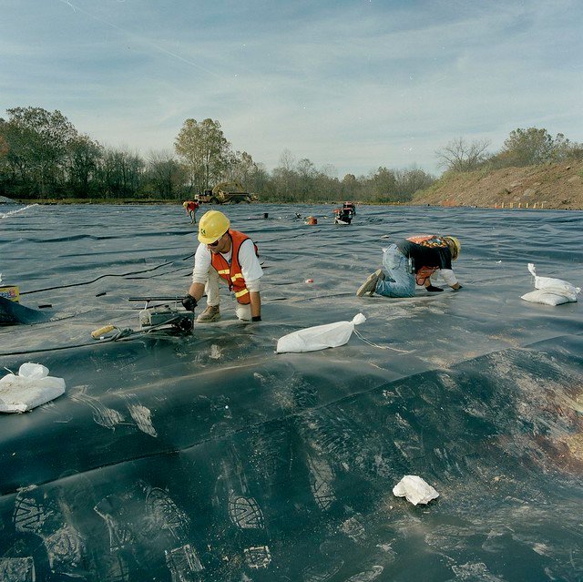
Installation
The installation quality of HDPE geomembranes determines the lifespan of the anti-seepage system and must strictly follow international standards such as ASTM D6392 and GRI-GM19.
Qualified installation begins with subgrade preparation; soil compaction must reach over 95% of Standard Proctor, and the surface must be free of gravel with a diameter exceeding 12mm (0.5 inches).
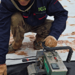
In the welding phase, a Dual-track Hot Wedge welder is the standard equipment for main seam connections.
It produces two parallel welds and reserves an air channel for 100% non-destructive air pressure testing.
Test pressure typically needs to be maintained at 25–30 psi (approx. 172–207 kPa) for at least 5 minutes.
Construction must adjust panel layout according to local climate; HDPE material can undergo physical expansion and contraction of about 30-40 cm per 100 meters under a 30°C temperature difference.
Subgrade Preparation
Clearing, Grubbing & Stripping
- Risk of Organic Matter Degradation: Any residual vegetation (roots, turf) will undergo anaerobic decomposition in the oxygen-deficient environment under the membrane, producing methane and carbon dioxide. The accumulation of gas causes “gas uplift,” resulting in the geomembrane bulging to form “whales,” which in severe cases can burst the membrane or destroy the welds.
- Stripping Depth: Topsoil stripping depth is typically controlled between 150mm and 300mm (6-12 inches) until the mineral soil is exposed. For areas with well-developed root systems, the excavation depth should extend at least 150mm below the bottom of the roots.
- Backfilling Voids: Voids left after removing stumps or large rocks cannot be simply backfilled with loose soil. Structural fill must be used in layers, with each layer not exceeding 200mm in thickness, and compacted using a handheld tamper (Jumping Jack) to the density level of the surrounding undisturbed soil.
Moisture & Compaction Control
OMC – Optimal Moisture Content
- Control Range: On-site soil moisture content should be controlled between -2% and +3% of the Optimal Moisture Content (OMC).
- Over-dry Treatment: If the soil is too dry, the friction between particles is high, making it difficult to compact and prone to collapse after absorbing water later. A water truck must be used to spray evenly, followed by mixing with a disc harrow.
- Over-wet Treatment: If the soil moisture content is too high, a “pumping” phenomenon will occur during compaction. Aeration or the addition of lime/cement is required for improvement.
Lift Thickness
It is strictly forbidden to fill too thick at one time; otherwise, sufficient compaction energy cannot be obtained at the bottom.
| Parameter | Cohesive Soil | Granular Soil |
|---|---|---|
| Loose Lift | Max 200mm (8 inches) | Max 300mm (12 inches) |
| Compaction Equipment | Sheepsfoot Roller | Vibratory Smooth Drum Roller |
| Passes | Usually 4-6 passes | Usually 3-5 passes |
| Testing Standard | ASTM D698 (Standard Proctor) | ASTM D4253 (Relative Density) |
- Function of Sheepsfoot Roller: For clay layers, the protrusions of the sheepsfoot roller can penetrate the soil layer, kneading and destroying the soil stratification, eliminating interface planes between layers, and making the bonding between upper and lower layers tighter, which is crucial for anti-seepage projects.
- Smooth Rolling: After completing compaction with the sheepsfoot roller, the final pass must use a smooth drum roller to level the surface and remove the “sheep foot” pits, providing a smooth interface for laying the membrane.
Surface Finishing
- Maximum Particle Size Limit: International standards (such as ASTM D698 Appendix) stipulate that on the substrate surface in contact with the geomembrane, there shall be no protrusions within 12mm (0.5 inches). In practice, many strict mining projects are more demanding, requiring the removal of all sharp particles larger than 6mm.
Removal and Covering:
Manual Picking
Before the final pass of smooth rolling, personnel should be arranged to walk in a line (Line Walk) to pick up exposed rocks, branches, wires, and other debris.
Buffer Layer Laying
If the gravel content in the original soil is too high to be completely removed, a layer of at least 150mm thick screened fine sand (sand bedding) or silty clay must be laid as a sacrificial layer.
- Wheel Tracks and Flatness: The compacted surface must not have obvious rutting. It is usually stipulated that under testing with a 3-meter straight edge, the gap shall not exceed 25mm. If the rut depth exceeds 25mm, it indicates insufficient substrate bearing capacity or too high moisture content, and it must be re-loosened, aired, and re-compacted.
Anchor Trench Preparation
Position and Geometric Dimensions:
- At least 1.5 meters from the crest edge to prevent excavation from causing the slope edge to collapse.
- Standard cross-sections are typically 0.5m (width) x 0.5m (depth) or 0.6m x 0.6m.
- Rounding: This is the most easily overlooked detail. The junction between the trench and the ground (where the geomembrane will bend 90 degrees into the trench) must be ground into an arc shape, with a radius typically no less than 100mm. Sharp 90-degree soil corners are strictly prohibited, as they act as stress fracture points when the membrane is under tension.
Trench Bottom Cleaning
The bottom of the trench must be level, dry, and free of standing water or loose soil.
Since mechanical excavation easily disturbs the original soil at the bottom, the final 50-100mm is usually required to be trimmed manually.
Anchor Trench
Excavation Operations
Excavated soil is strictly prohibited from being piled on the 1.5-meter buffer zone between the anchor trench and the slope crest.
The correct practice is to pile the spoil on the side of the anchor trench facing away from the slope (the rear), maintaining a distance of at least 0.5 meters.
Temporary Drainage Control
Water accumulation in the trench will soak the trench walls, causing softening and collapse, or result in a muddy trench bottom where the membrane cannot be laid.
During rainy season construction, temporary drainage gaps must be set behind the trench walls every 50 to 100 meters or mobile submersible pumps must be configured.
Before heavy rain arrives, the site foreman must check drainage flow; laying HDPE membranes in trenches with standing water is strictly prohibited.
Edge Rounding
- Rounding Standards
When the geomembrane extends from the slope into the anchor trench, a 90-degree bend occurs at the upper edge of the trench. If this edge is an untreated right-angled soil block or contains sharp stones, the contact point will generate extremely high stress concentration when the membrane is tightened, cutting the membrane like a knife.- Operational Requirements: Dedicated personnel must be assigned to use shovels or handheld grinders to trim the upper edge of the trench on the slope side into a smooth arc. International standards suggest a radius of no less than 100mm. Any acute angles are strictly prohibited.
- Reinforced Buffer Layer
Under geological conditions with high gravel content or hard soil, simple soil trimming is insufficient to eliminate the risk of puncture. In such cases, an additional layer of 500g/m² short-fiber non-woven geotextile must be laid at the corner as a sacrificial layer. This geotextile is usually 1 to 2 meters wide and must completely cover the slope crest corner and extend to the bottom of the trench, completely isolating the HDPE membrane from the rough substrate.
Membrane Placement in Trench
- U-shaped Locking Configuration
Large landfills or steep slope projects typically adopt a “U-shaped” layout. That is, the membrane not only covers the bottom of the trench but also extends up the rear wall of the trench and may even extend 30 to 50 cm horizontally on the ground after clearing the trench. This configuration utilizes the frictional resistance of the three surfaces of the trench, providing the maximum pull-out coefficient. - No Welding Inside Trench
Absolute prohibition of hot wedge welding at the bottom or corners of the anchor trench.- If the longitudinal seam of two sheets extends into the trench, the welding and testing must be completed on flat ground before the membrane is placed in the trench.
- Trench space is narrow and the bottom is uneven, so the welder’s pressure cannot remain constant during travel, easily resulting in cold welds or missed welds. Once backfilled, these defects can never be repaired.
Backfilling and Temperature Control
The thermal expansion coefficient of HDPE is approximately $1.2 \times 10^{-4}$.
Under a 30°C temperature difference, the length change of a 100-meter-long membrane can reach 36 cm.
- Failure Scenario: If the anchor trench is completely backfilled and compacted during the high temperatures of midday (when the membrane surface temperature may reach above 60°C), the membrane is in a state of extreme expansion and elongation. At night, when the temperature drops sharply, the membrane attempts to shrink. Since the top is locked tight by backfill, the huge shrinking tension will act entirely on the corner at the base of the slope.
- Bridging Effect: This tension pulls the membrane up from the base of the slope, creating a trampoline-like “bridging” state. Once suspended, the weight of the overlying stack or waste liquid will instantly tear the membrane at the base. This is one of the most common causes of geomembrane failure globally.
“Temporary Weighting, Timed Locking” Construction Method
To avoid the aforementioned risks, the standard international construction procedure is as follows:
- Temporary Fixation during the Day: On the day the membrane is laid, only place sandbags every 2 to 3 meters in the anchor trench to prevent wind lift; strictly prohibit immediate earthwork backfilling. At this time, the membrane can slide freely in the trench, releasing thermal stress.
- Early Morning Backfill Locking: The best time for backfilling is the following early morning (usually 4 AM to 6 AM). This is when the ambient temperature is lowest, the membrane is in its shortest contracted state, and it fits the slope most tightly.
- Locking Logic: Backfilling and compacting at the coldest moment is equivalent to locking the “shortest length” of the membrane. Subsequently, as the temperature rises during the day, the membrane will only become loose (producing tiny waves) rather than generating destructive tensile stress.
Backfill Materials and Equipment
- Screened Backfill: Backfill soil must be fine soil passed through a 25mm sieve and must not contain large rocks. If the original soil does not meet the standard, backfill must be sourced externally.
- Layered Compaction: Backfilling should be done in layers, with each loose soil layer thickness controlled within 200mm.
Equipment Restrictions
The use of heavy rollers in the trench is strictly prohibited to avoid collapsing the trench walls or crushing the membrane.
Only walk-behind vibratory plate compactors or rammers can be used.
Operators must be specifically trained to ensure the tamper head maintains a safe distance from the membrane to avoid impact.
Membrane Deployment & Layout
Panel Layout Management
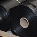
Before any roll of geomembrane arrives on site, the technical department must complete the drawing and approval of the Panel Layout.
- Unique Identification (Panel ID)
Every piece of membrane (Panel) laid on site must have a unique number (e.g., P-001, P-002). This number must be clearly marked at both ends of the membrane using a white marker. On-site recorders must document the roll number, laying date, time, and ambient temperature corresponding to each ID. This establishes a complete material traceability chain; if a quality issue occurs, it can be traced back to specific production batches. - Loss Rate Control
Reasonable arrangement can control the material loss rate within 5%. In corners with irregular shapes or closure areas, the optimal cutting plan must be calculated through CAD simulation on drawings; unpanned “experimental cutting” on site is strictly prohibited as it generates large amounts of unusable, expensive waste. - Seam Reduction Principle: The logic of the layout is “seam minimization.” Every weld is a potential leakage risk point. Therefore, when conditions allow, preference should be given to rolls with larger widths (such as 7 or 8 meters wide) to reduce on-site welding workload and testing costs.
Weather Constraints
Geomembrane laying is an entirely open-air operation and is extremely sensitive to meteorological conditions.
| Meteorological Indicator | Threshold Limit | Potential Consequences |
|---|---|---|
| Wind Speed | > 32 km/h (20 mph) | Membrane is lifted like a giant sail, potentially causing injury or equipment damage; unable to align overlap edges. |
| Temperature (Low) | < 0°C (32°F) | HDPE material becomes brittle, prone to micro-cracks when unfolding; difficulty in preheating welders, unstable weld quality. |
| Temperature (High) | > 40°C (104°F) | Membrane expands excessively, producing severe wrinkles, preventing flat welding; high risk of heatstroke for personnel. |
| Precipitation/Humidity | Rain, Snow, Heavy Fog | Welding surface becomes damp; water vapor evaporates instantly forming weld pores (wormholes), leading to airtightness test failure. |
- Wind Management: When the sustained wind speed on site exceeds 20 km/h, sandbag weighting must be increased. When gusts exceed 32 km/h, laying operations must stop immediately, and the edges of laid but unwelded membranes must be temporarily secured.
- Humidity Control: HDPE welding requires the contact surface to be absolutely dry. If there is dew in the early morning, it must be dried with a blower or wiped with an absorbent towel, and operations may only proceed after a test weld passes.
Slope Deployment
- Vertical Laying Principle
All membranes on the slope must be laid in the direction of the “maximum slope line” (from the crest toward the toe). Joints are also vertical.- Mechanical Logic: If horizontal laying is used, the horizontal joints will bear vertical downward shear peel stress, which is the weakest direction for hot wedge welds. Vertical welds primarily bear tensile forces, which is the strength of HDPE material and welds.
- 1.5-meter (5-foot) Exclusion Zone
According to GRI-GM19 specifications, transverse butt seams on the slope are strictly prohibited. If a roll is not long enough to cover the entire slope, the seam must be located in an area extending at least 1.5 meters from the toe onto the flat bottom.- Reason: The toe is a transition point for stress concentration and prone to liquid accumulation. Moving the seam to a flat and lower-stress area significantly reduces the risk of cracking.
- Temporary Anchoring
When laying slope membranes, they must first be temporarily fixed in the anchor trench at the top (using sandbags or clamps) before being unfolded downward. Suspending the membrane on the slope without fixation is strictly prohibited as it may slip and cause injury.
Overlap & Placement
- Shingle Overlap
The overlap of two adjacent membranes must follow the direction of water flow or slope. The upstream (or higher) membrane must be placed on top of the downstream (or lower) membrane.- Function: Prevents rainwater or leachate from scouring the weld edge; even if the weld has minor defects, liquid will flow over it rather than into the interlayer.
- Overlap Width Specification
- Dual-track Hot Wedge Welding: Standard overlap width is 100mm to 150mm (4-6 inches). This provides sufficient grip space for the welder’s drive wheels and ensures enough peel test tabs on the outside of the weld.
- Extrusion Welding: Overlap width is typically 75mm (3 inches).
- Flatness Adjustment
Before welding, serious wrinkles in the overlap area must be eliminated by manual pulling or “kicking” the membrane. While HDPE allows some waves, the 10-15cm width where the welder travels must be absolutely flat; otherwise, it will cause the welder to jump, resulting in cold welds or burn-through.
Thermal Expansion Management
HDPE is a thermoplastic material with a very high thermal expansion coefficient (approx. $1.2 \times 10^{-4}$ /°C).
This causes the membrane to rise and fall like waves under sunlight, commonly known as “wrinkles.”
- Pros and Cons of Waves
- Moderate Waves: During high-temperature periods, the membrane must have some waves. This represents redundancy for thermal expansion. If the membrane is laid as flat as a mirror in high heat, it will tighten like a drumhead when temperatures drop at night, generating extremely high tensile stress and causing weld tearing.
- Excessive Waves: If waves are too high (e.g., exceeding 15cm) or fold over, the welder cannot pass.
- Construction Timing Selection
- Hot Regions: Laying operations should be concentrated in the early morning (5:00 – 10:00) or evening. Avoid alignment operations during midday when membrane surface temperatures are 50°C – 60°C.
- Compensation Method: If construction must occur in high heat, experienced installers will reserve more slack at the overlap or even manually create small arches to offset nighttime cold contraction.
- Bridging Prevention
This is the opposite of wrinkles. When the membrane is laid too tight in low temperatures or after laying in high heat followed by nighttime contraction, a phenomenon occurs at the slope toe where the membrane detaches from the soil and hangs suspended.- Hazards: Suspended membranes will be forced against the corner when under overlying pressure (such as backfill or water pressure), leading to catastrophic tearing.
- Countermeasure: Personnel must step on the slope toe to ensure the membrane is tight against the internal corner and reserve sufficient slack.
Visual Inspection
The laying process is also an opportunity for a final comprehensive checkup of the material.
Despite factory QC, damage can occur during transport and on-site handling.
- Check Points
- Scratches and Creases: Scratches deeper than 10% of the membrane thickness must be marked and repaired. Severe creases can lead to stress cracking and usually need to be cut out.
- Manufacturing Defects: Such as gels, uneven carbon black dispersion, or edges not meeting thickness standards.
- Perforations: Pay attention to light spots, which usually indicate pinholes.
Marking Process
Laying personnel should carry a white paint pen.
Once any suspicious point is found, immediately circle it on the membrane and label the specific defect type (e.g., “Cut”, “Hole”).
CQA Testing
Non-Destructive Testing, NDT
Air Pressure Test
The air channel (approx. 10mm wide) reserved between the two parallel welds produced by the hot wedge welder is designed for this test.
- Equipment and Preparation
- Use a hollow needle with a pressure gauge and insert it into the air channel at the end of the weld.
- Both ends of the channel must be heat-sealed or closed with clamps to form an airtight, long-strip gas chamber.
- Pressurization Procedure
- Start the air pump to inflate the channel. For 1.5mm – 2.0mm HDPE membranes, the standard test pressure is 25 psi to 30 psi (approx. 1.7 – 2.1 bar).
- Stabilization Period: After inflation stops, wait for 2 minutes for the compressed air temperature to stabilize, eliminating reading errors caused by adiabatic compression.
- Test Period: After stabilization, start timing for 5 minutes.
- Pass/Fail Criteria (ASTM D5820)
- Pressure Drop: At the end of 5 minutes, the pressure gauge reading must not drop by more than 4 psi (0.28 bar). If the gauge needle returns to zero or drops significantly, a through-leak exists in the weld.
- Continuity Check: This is the easiest stage to falsify, so a CQA engineer must be present for supervision. After the test passes, the technician must walk to the other end of the weld (which could be 100-200 meters away) and cut the air channel seal. A clear “hissing” sound of releasing gas must be heard.
- Logic: Only by hearing the air release can it be proven that the entire channel is unobstructed and the pressure test covered the full length. If there is no sound, the channel is blocked in the middle (usually due to fusion caused by welder jumping), making the test invalid and requiring step-by-step troubleshooting.
Vacuum Box Test
For extrusion welds, patches, and irregular areas where air pressure testing is impossible, the vacuum box method must be used.
- Operation Process
- Apply Soap Solution: Brush a layer of foaming agent or soapy water on the weld surface to be tested.
- Apply Vacuum: Place a rectangular vacuum box with a viewing window over the weld, start the pump, and bring the internal negative pressure to at least -5 psi (-35 kPa).
- Observation: Maintain negative pressure for at least 10 to 15 seconds. Observe if soap bubbles continuously emerge within the viewing window.
- Limitations and Overlap
- The vacuum box is usually only 0.6 to 1 meter long. Long welds must be tested in sections.
- Overlap Zone: Adjacent test areas must overlap by at least 75mm (3 inches) to prevent missed inspections at the junctions.
| Test Method | Applicable Weld | Pressure Standard | Duration | Criterion |
|---|---|---|---|---|
| Air Pressure Test | Dual-track hot wedge weld | 25 – 30 psi | 5 minutes | Pressure drop < 4 psi + remote air release sound |
| Vacuum Box Test | Extrusion weld, repairs | -5 psi (negative) | > 10 seconds | No continuous bubble generation |
Destructive Testing, DT
- Sampling Frequency
The minimum international sampling frequency is one sample every 150 meters (500 feet) of weld. During the early stages of installation or when encountering complex nodes, CQA engineers have the right to increase frequency. - Sample Size and Allocation
Once a sample location is selected, a weld sample approximately 12 inches (wide) × 30-40 inches (long) is cut. The sample is immediately marked and divided into three parts:- Archive Sample: Kept by the owner or CQA agency for long-term storage.
- Installer Sample: Tested on-site by the construction team for rapid feedback on process parameters.
- Lab Sample: Sent to an independent GAI-LAP certified laboratory for final determination.
- Repair Principle: The large hole left by sampling must be immediately covered with an HDPE patch, repaired by extrusion welding, followed by a vacuum box test of the repaired area.
Laboratories follow ASTM D6392 standards, cutting the sample into 1-inch wide specimens for two types of tests:
- Shear Test: Simulates tension parallel to the membrane surface to test the tensile strength of the weld.
- Peel Test: Simulates tearing the two layers of membrane apart to test the bonding quality of the fusion interface.
Usually, 5 shear specimens and 5 peel specimens are tested per sample set (for dual-track welds, the inner and outer welds must be tested separately, totaling 10 peel specimens).
A. Strength Value Requirements
Qualified weld strength must reach a certain percentage of the parent sheet strength.
Below are the general GRI-GM19 standards for 1.5mm HDPE smooth geomembrane:
- Shear Strength: Must reach over 95% of the sheet yield strength (approx. 120 lb/in or 21 kN/m).
- Peel Strength: Must reach over 62% of the sheet yield strength (approx. 78 lb/in or 14 kN/m).
B. Failure Mode – FTB is the only standard
In international engineering, meeting numerical values is only a necessary condition; the failure mode is the sufficient condition.
FTB (Film Tear Bond) is the only acceptable mode.
- FTB (Pass): During tension, the weld is not torn apart; instead, the parent material next to the weld breaks. This proves the “welded connection is stronger than the material itself.”
- AD (Adhesion Failure / Fail): The two layers of membrane separate at the weld interface, like peeling tape. Even if the tension value is high, it is judged as non-conforming. AD occurs due to insufficient temperature or pressure, where the two layers do not truly fuse at the molecular level and are only “stuck” together, destined to crack during long-term use.
Destructive sampling is performed every 150 meters (500 feet) of weld to conduct shear and peel strength tests.
Only the “Film Tear Bond” (FTB) mode, where the break occurs in the parent material rather than the weld interface, is considered qualified.