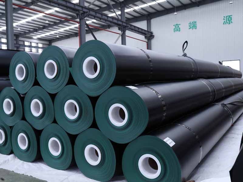
Selecting non-woven geotextile requires focus on weight (commonly 150–400g/㎡), tensile strength (≥8–20kN/m), and water permeability (permeability coefficient 10⁻³–10⁻¹cm/s). Road engineering prioritizes high strength, while drainage engineering emphasizes water permeability. It is recommended to choose products complying with GB/T 17638 standards and match models based on foundation bearing capacity and construction environment to ensure durability reaches 5–20 years.

Determine the Primary Application
Determine primary use before selecting model: for drainage filtration, choose geotextile with permeability coefficient 10⁻³–10⁻¹cm/s and weight 150–250g/㎡; for road reinforcement or isolation, 300–400g/㎡ with tensile strength ≥12–20kN/m is suggested; for protection (such as slope protection), high puncture resistance (≥1.5kN) is required. Different working conditions correspond to different performance indicators; reasonable matching ensures an engineering life of 10–20 years.
Engineering Purpose Classification
Before writing non-woven geotextile into construction documents, clearly state what it is “responsible for” in the structure. FHWA classifies common functions in transportation engineering into separation, filtration, drainage, reinforcement, and explains that stabilization is often not a single function, but rather separation, filtration, and reinforcement working together, with drainage sometimes involved. Placed between subgrade and base, wrapped outside drainage pipes, attached to filter layers behind walls, or pressed under slope protection riprap—different positions mean the indicators to be checked later will also change.
Match the application and position first, only then can aperture, permeability, thickness, and construction survivability be discussed. FHWA’s Table 7-14 matches applications clearly: separation is common between subgrade / aggregate base, and also between railway ballast and old/new asphalt layers; reinforcement is common on unpaved roads, paved roads, airports, and construction platforms on soft soil foundations; filtration is common below base, subbase, or ballast; drainage is used for horizontal water conduction and interception or placed below other geotechnical systems.
The table below is suitable for the main text, allowing readers to understand “classify by use first, then select by parameters” at a glance. The correspondence between position and function in the table comes from FHWA transportation use classifications and NRCS road stabilization, subsurface drainage, and slope protection construction usages.
| Placement Position | Initial Category | Primary Task | Supplementary Data Needed |
|---|---|---|---|
| Between subgrade and aggregate base | Separation | Prevent fine soil upwelling and aggregate embedding | CBR, coverage thickness, equipment type |
| Road edge drainage or base drainage system | Filtration | Allow water into system, keep fines outside | D85, D15, Proportion below No.200 |
| Blind drains, perforated drainage pipe wrapping | Filtration + Drainage | Inflow without clogging, maintain long-term flow | Effective aperture, permeability, clogging resistance |
| Construction platforms on soft soil foundations | Reinforcement / Stabilization | Distribute load, reduce deformation | CBR, load, whether paired with geogrid |
| Below slope protection stones, riprap | Filtration + Protection | Prevent fine soil loss, protect slope surface | Coverage time, rock fall height, seams |
| Behind retaining walls or filter layers | Filtration | Prevent backfill soil from entering drainage layer | Soil sample gradation, long-term flow direction |
Many materials conflate “separation” and “filtration,” which leads to errors on-site. FHWA is specific in road chapters: when geotextile serves as a separation layer, it must not only prevent mixing of permeable base and adjacent subgrade or subbase but also satisfy filtration conditions; if it must withstand construction traffic, it must further satisfy survivability and endurance. Translated into construction language: for fabric laid under roads, separating soil and stone is not enough—it must allow water through and not be crushed during the construction phase.
Even if both are labeled “nonwoven geotextile,” the judgment sequence for placement under subgrade versus wrapping a drainage pipe will not be the same.
The former checks separation first, then supplements with filtration and construction survivability; the latter checks filtration first, then supplements with long-term inflow and clogging resistance.
On weak foundations, the application must go one step further. FHWA explains that stabilization is not an isolated function, but the joint action of separation, filtration, and reinforcement; drainage sometimes participates. It also provides practical boundaries: road separation conditions commonly use Class 2, applicable boundaries often found at CBR>3, with at least 150 mm (6 in.) of base or subbase above, and using conventional weight equipment; if CBR<3 or equipment is heavier, moving to Class 1 is suggested. In other words, if the subgrade is soft, writing “for separation” is often insufficient; stabilization purposes should be included in the documents.
Engineering purposes can be compressed into 3 groups of short sentences, which are easier to read in the main text than long explanations:
In pavement structures
Between subgrade / base, mostly check separation first
When water enters side ditches or base drainage layers, supplement with filtration
CBR 3 is a common boundary; below this, stabilization use is more prominent
Between tires and fabric during construction, FHWA requires maintaining a 150 mm cover layer
In subsurface drainage
Wrapping drainage pipes, blind drains, French drains—check filtration first
If water must also travel along the material plane, supplement with drainage capacity
NRCS requires wrapping materials to prevent soil entry into the drainage body throughout system life
When silt content exceeds 40%, long-term clogging risk must be verified
In slope protection and cover layers
Below stone, riprap, slope surface protection layers—mostly filtration plus protection
NRCS requires slope materials to be anchored and covered within 48 hours, or take anti-UV measures
Stone cannot be pushed or rolled on bare fabric
Rock fall height on bare fabric is often specified as not exceeding 3 ft
Looking back at subsurface drainage, misstating engineering purposes will bias all subsequent parameters. NRCS Subsurface Drain standards require filter materials to prevent soil entry into the drainage system and maintain flow conditions throughout the design life; for corrugated plastic pipes of diameter 8 in. and below, specifications also mention trench bottom support and wrapping layer conditions—gravel wrapping can be taken as at least 3 in. thick, and wrapping flow path length should also be no less than 3 in. In these conditions, the fabric’s task is not to “separate two layers of material,” but to “let water in, keep fines out, and not clog after many years.”
If the drawing only says “geotextile for drainage,” information is still insufficient.
A more usable description is: wrapping object, contact soil layer, flow direction, design life, fines proportion, whether a gravel transition layer is needed.
Construction platforms, temporary roads, and soft foundation subgrades are another category. Here, what’s common is not just “separation,” but also allowing equipment to travel on top. FHWA’s reminder for soft subgrades is clear: separation layers must also satisfy filtration and construction survivability; heavy equipment, thin cover layers, and low CBR will increase the stress conditions on the fabric. NRCS in road stabilization uses describes laying methods as loose-laid parallel to the road centerline, with minimum overlap for unsewn panels typically taken as 24 in., and backfill drop height on bare fabric not exceeding 5 ft.
Material descriptions should follow suit. Writing only “200 gsm nonwoven geotextile” makes the engineering task incomplete; for road, drainage, and slope protection conditions, a more useful expression is “purpose + position + contact layer + flow direction + construction conditions.” For example: separation layer for unpaved road, subgrade CBR 4–5, overlying aggregate 150 mm, conventional equipment construction; or filter layer for subsurface drain, contact soil sample fines 42%, required not to clog within design life.
Soil Layer & Water Flow
The same non-woven geotextile, placed under road base, outside perforated drainage pipe, or in a filter layer behind a wall, will not have the same judgment methods. When looking at soil layers, don’t just distinguish “sand” or “clay,” but also draw the water’s path: does water pass vertically through the fabric into the drainage layer, or pass through the fabric then travel sideways along the fabric surface? FHWA distinguishes this clearly: geotextile must match soil gradation and permeability; non-woven geotextile can also act as a drainage layer, so one cannot only fixate on weight or tensile strength.
Water only passes through the fabric—check filtration first;
Water also travels along the fabric—filtration is not enough, check drainage capacity too.
After completing soil sample data, the subsequent aperture, water permeability, and anti-clogging judgments have a basis. FHWA’s filtration design steps are specific: first obtain the protected soil’s D85, D15, and percentage passing 0.075 mm (No.200) sieve, then look at the permeability coefficient of the base or drainage layer in contact with the fabric, and finally compare with geotextile AOS, permeability, and vertical water permeability capacity. Without these sets of numbers, writing only “for drainage” or “for separation” provides far from enough information.
In drawings and inquiries, the soil layer data set should include at least 6 items:
Protected soil’s D85
Protected soil’s D15
Proportion of fines below No.200 sieve
k value of upper base or drainage layer
Soil’s USCS / AASHTO classification
Water table position, whether there is pumping or seasonal softening
With soil data, filtration conditions can be converted to numerical values. Common criteria given by FHWA for road and side ditch filtration applications are: non-woven geotextile AOS ≤ 1.8 × D85, geotextile permeability coefficient k_geotextile ≥ k_soil or k_base/subbase, vertical water permeability capacity ψ ≥ 0.1 sec⁻¹. If the soil belongs to non-cohesive silt and is prone to pumping, FHWA also suggests controlling openings more strictly, looking at AOS ≤ D85, and performing laboratory filtration tests rather than using only a set of nominal parameters on a standard sample page.
When fines are high, pumping is obvious, or there’s repeated water flow disturbance,
opening selection cannot just be based on being “permeable enough.”
Further down, it’s not as simple as “finer soil, thicker fabric.” NRCS in subsurface drainage specifications lists several soil layers prone to problems separately: dispersed clays, silts with plasticity index less than 7, fine sands with plasticity index less than 7, soils that crack due to wetting/drying changes, and installation conditions where compaction between pipe and backfill might be insufficient. For such sites, specifications require joint verification of effective opening size, strength, durability, permeability; if soil silt content exceeds 40%, confirm the geotextile will not clog during the design life.
Encountering the following soil layers, specify separately in documents:
dispersed clays
silts with PI<7
fine sands with PI<7
Soils that crack after drying shrinkage
Trenches difficult to compact between pipe exterior and backfill
Soil layers with silt content >40%
Continuing with water flow, many project problems arise from “wrong flow direction.” Fabric wrapped outside drainage pipes primarily faces normal inflow; here, aperture, vertical permeability, and anti-clogging are checked first. Fabric behind walls or in composite drainage layers, if undertaking in-plane water conduction, cannot just look at permittivity, but must check in-plane conduction indicators. FHWA mentions non-woven geotextile can be used as a drainage layer, and transportation system materials list “thick needle-punched non-woven fabric attached to soil for in-plane drainage” as a separate design scenario.
Different water flow paths mean different material focus points:
Inflow focuses on aperture and vertical permeability; water traveling along fabric also focuses on in-plane conduction.
In very fine soils, one must prevent “fabric not breaking, but flow slowly dropping.” US Army Corps of Engineers manual for filter fabric selection gives stricter boundaries: for granular soils with less than 50% fines below No.200 sieve, filter fabric EOS/d85 ≤ 1; if soil is finer, EOS cannot be larger than No.70 sieve; if over 85% of material in base soil passes No.200 sieve, filter fabric should not be used alone—usually an intermediate sand layer transition is added. The manual also takes gradient ratio ≤ 3 as the control value for compatibility between filter fabric and adjacent soil layers.
In water flow judgment, it’s best to supplement drawings with these sentences:
Whether water enters pipe, enters trench, or travels along fabric to the side
Whether fabric exterior contacts soil or contacts graded stone first
Long-term drainage or short-term construction drainage
Proportion of fines below No.200 in soil
Whether a gravel wrapping layer is needed instead of just fabric
Whether to perform gradient ratio or laboratory filtration compatibility tests
If the project is subsurface drainage, NRCS provides a practical reference: when not relying solely on geotextile but using a gravel wrapping layer, wrapping material should meet 100% passing 1.5 in. sieve, No.60 sieve passing not exceeding 30%, No.200 sieve passing not exceeding 5%. This doesn’t mean all drainage systems must change to gravel wrapping, but reminds: when soil is extremely fine, clogging probability high, and installation difficult to control, geotextile alone might be unsuitable—the water path and soil layer must be redrawn together.
Construction and Service Life
Describing non-woven geotextile to this point cannot stop at usage terms like “separation, filtration, drainage”—construction conditions and planned service life must be included. FHWA gives clear boundaries for road separation conditions: When subgrade CBR>3, at least 150 mm (6 in.) of base or subbase above, and using conventional weight equipment for construction, it is usually considered under Class 2 survivability rating; when CBR<3 or equipment is heavier, move to higher survivability requirements.
Compress site information into a table first, then subsequent specifications, overlaps, repairs, and coverage times can be written accurately. NRCS construction specifications require materials to be stored in clean, dry, light-protected locations before use, following ASTM D4873 for site receiving, storage, and handling; laying surfaces must be smooth, without loose rocks, soil clumps, holes, protrusions, mud, or standing water.
| Site Condition | Data to Check First | Common Description |
|---|---|---|
| Subgrade Strength | Whether CBR is above 3 | Do not treat as ordinary separation layer when below 3 |
| Coverage Thickness | Whether base/subbase ≥ 150 mm | Always retain 150 mm between tires and fabric |
| Equipment Type | Conventional or heavy equipment | Heavy equipment requires higher survivability |
| Exposure Time | Days exposed before covering | Specify same-day, within 48h, or within 14 days coverage |
| Seam Method | Overlap or sewing | Values like 18 in., 24 in., 300 mm must be clear |
| Repair Method | Patch size and margins | Same-material patch, fixed size beyond damaged edge |
This table is not just for procurement’s amusement; it affects whether material can maintain its original filtration and separation state after backfill and compaction. For road separation layers, FHWA writes that at least 150 mm of base/subbase thickness should be maintained between tires and geotextile throughout the construction process; if the site cannot achieve this, looking only at laboratory strength tables is of little significance.
Check these items before construction:
Subgrade CBR>3 or <3
Whether upper cover layer is ≥150 mm
Whether equipment is conventional weight
Whether material is stored/transported per ASTM D4873
Whether rolls are placed in clean, dry, light-protected locations
Whether base surface is free of loose rocks, holes, mud, and standing water
After clarifying pre-construction conditions, the next step is laying and backfilling. NRCS requires geotextile to be loose-laid along the base, not pulled tight, and before cover material is laid, temporary fixation methods cannot punch new holes in the fabric. Sewing and overlapping shouldn’t be confused: when sewing, seam edge overlap 6 in., two parallel lock-type stitch lines, seam strength at least reaching 90% of material’s weak-direction tensile strength; when not sewing, conventional minimum overlap is written as 18 in. For road stabilization conditions, NRCS also writes minimum overlap for unsewn joints as 24 in.
These numbers affect more than construction convenience. Overlaps too narrow easily open under backfill pressure; seam strength too low leads to joint failure before fabric breaks; too many temporary fixation punctures cause local filter layer failure. UFGS provides similar wording: Overlapping seams usually not less than 300 mm (12 in.); when subgrade is weak or large differential settlement expected, should be greater than 300 mm; when soil CBR<1, seams usually change to sewing.
During laying and backfilling, the documents should ideally include:
Fabric loose-laid, do not pull tight
Sewn edge overlap 6 in.
Seam strength ≥90% weak-direction tensile strength
Non-sewn overlap ≥18 in.
Road stabilization non-sewn overlap ≥24 in.
Weak subgrade can use above 300 mm overlap
Prioritize sewing when CBR<1
Further on, service life and exposure time should be checked together. NRCS clauses for different uses are specific: in slope protection conditions, fabric should be anchored and covered within 48 hours, or take UV measures; in subsurface drainage, coverage should be completed within the same working day; in road stabilization, height of backfill material falling onto uncovered fabric shall not exceed 5 ft, and stone cannot be pushed or rolled on bare fabric. In long-term buried projects, much early damage occurs during this period, not years into service.
UV stability should also not be omitted. NRCS tables list UV requirements for many non-woven geotextiles as ASTM D4355, retained strength ≥70% after 150 hours exposure; in UFGS example indicators, UV degradation is often written as retaining 50% after 500 hours. The two documents use different exposure durations but express the same thing: if exposure, slow segmented construction, or early material spreading occurs on-site, check anti-UV data first, don’t wait until fabric turns white or brittle to supplement.
Regarding points related to service life, check this set first:
Exposure duration before covering: hours, days
Whether same-day coverage or coverage within 48 hours is required
Whether backfill drop distance ≤5 ft
Whether stones are pushed on bare fabric
Is UV indicator 150 h / 70% or 500 h / 50%
Whether the site will have staged exposure and repeated material handling
Address rework and repairs. NRCS stipulates that if tears, punctures, overlap disturbance, subgrade pumping, foreign matter embedding, or elevation distortion occur, surrounding backfill must be removed and base surface restored first; repair using same type of material. If original seams required sewing, patch must extend at least 1 ft beyond damaged edge; if originally overlapping, patch must extend at least 2 ft beyond damaged edge.
Select the Right Weight/Thickness
When selecting non-woven geotextile, weight and thickness affect strength and filtration results. Generally, 150–250g/㎡ with thickness approximately 1.5–2.5mm can be chosen for greening or drainage engineering; 300–400g/㎡ with thickness ≥3mm, corresponding to tensile strength approximately 12–20kN/m, is recommended for roads or foundation reinforcement. Higher weight leads to better puncture resistance and service life (up to 10–20 years), but costs also increase; matching should be reasonable based on load and working conditions.
Purpose
Many product pages list 150 g/m², 200 g/m², 300 g/m² first, but engineering asks first not about numbers, but where this fabric layer is placed and what it does. Road and drainage specifications categorize geotextile uses into subsurface drainage, separation, stabilization, erosion control, paving fabric, etc.; road application materials further distinguish separation, filtration, drainage, reinforcement, protection.
Look at placement between subgrade and aggregate first. Materials explain separation clearly: placing fabric between soft subgrade and aggregate base is to reduce mixing of the two material layers; without a separator, the base will be contaminated by fines from below. This position checks installation survivability, tear resistance, puncture resistance, and post-laying integrity—weight and thickness serve “can be laid, can be pressed, and layers haven’t mixed after a period of use.”
Then look at filter positions. Filtration refers to water flowing through the fabric thickness direction while controlling soil particles within allowable ranges; materials describe it as cross-plane flow, which is vertical water passage. This position cannot just say “use thicker non-woven fabric,” but must include AOS and permittivity. ASTM D4751 explains AOS as the approximate maximum opening size through which soil particles can pass; ASTM D4491 takes permittivity as an indicator of water passing through geotextile, explaining it’s measured under uncompressed, isolated conditions—caution is needed for site application.
Switch to planar drainage position. Drainage is not as simple as “permeable,” but water traveling along the fabric plane direction; public materials state clearly that this use is usually handled by thicker non-woven geotextile, with capacity expressed by transmissivity, related to “thickness under specified normal pressure.” That is, thickness here isn’t secondary data, but tied to in-plane conduction capacity. Using light fabric meant for separation for drainage might have similar nominal weights but will perform very differently in working states.
Then look at protection use. Protection is defined in materials as letting geotextile act as a stress relief layer, spreading local contact stress to reduce damage to material below. Geomembrane protection is most typical; GRI non-woven protection specifications target geomembrane cushioning, with common mass ranges given as 340–2000 g/m².
Discussing weight here is usually not for vague “sturdiness” but to look at thickness, rebound, and puncture resistance together. ASTM D6241 uses a 50 mm probe to measure static puncture resistance; probe size applies multi-directional force to the fabric, which is closer than tensile testing to the stress on membrane under stone cover.
The following comparison table places common non-woven geotextile uses and corresponding performance items together, which is closer to construction judgment than just comparing gsm.
| Clear Purpose to Specify First | Common Placement | Data to Check First | Understanding Weight/Thickness |
|---|---|---|---|
| Separation | Between aggregate base and soft subgrade | Installation survivability, puncture, tear, seams | First ensure no breakage or layer mixing after construction |
| Filtration | Filter layers, trench drain wrapping | AOS, permittivity, long-term clogging risk | Not the thicker the better; must match soil particles |
| Drainage | Positions needing in-plane water conduction | transmissivity, thickness, compression state | View thickness and in-plane conduction together |
| Protection | Above/below geomembrane, high local stress areas | Nominal thickness, D6241, rebound | Consider buffering and pressure spreading ability first |
| Stabilization assist | Weak subgrade, repeated traffic load positions | Separation, friction, puncture, construction state | Deconstruct primary use first, then set weight |
Ask first if this fabric layer is blocking soil, passing water, conducting water, or cushioning a membrane; after asking, look at numbers like 200, 300, 400.
Continuing further, procurement tables should at minimum write “purpose” to the point where test items can be judged. Writing only non woven geotextile 250 g/m² is insufficient for both separation and filtration; once written as “for trench drain filtration” or “for geomembrane protection,” data for D4491, D4751, D6241, D5199 have a place. ASTM D5199 also reminds that thickness is nominal thickness, not minimum thickness, and cannot represent site thickness under variable pressure; thickness of some geosynthetics changes significantly with normal load.
Placement layer: subgrade interface, trench, above membrane, below membrane, within backfill stone
Primary purpose: separation / filtration / drainage / protection
Adjacent material: silt, sand, gravel, rounded gravel, geomembrane
Flow direction: vertical through fabric, or along the fabric plane
Stress method: construction vehicles, compaction, long-term cover, local angular contact
Tests needed: D4491, D4751, D6241, D5199
Site Conditions
Putting gram weight and thickness into the site context will make the judgment more stable. FHWA mentions in road materials that when geotextiles are used for weak, wet subgrades, a common reference line is a subgrade CBR less than 3, corresponding to a resilient modulus lower than 30 MPa (4500 psi); this type of foundation is prone to obvious rutting under conventional construction. At this stage, choosing the fabric is not just about “separating soil and stone,” but also looking at construction vehicles, aggregate edges, compaction requirements, and whether it can maintain integrity after laying.
Look at the subgrade itself first. Silt, clay, fine sand, and mixed fill react differently after being compressed; laying the same layer of aggregate, soft clay is more easily pressed with wheel tracks of more than 30–75 mm, and fine materials are also more easily pumped to the upper layer. FHWA writes very clearly that as a separation layer, geotextiles must prevent the permeable base and adjacent subgrade from mixing, and must also satisfy filtration and construction survivability requirements, so the softer the foundation, the more you cannot just look at a row of gsm numbers.
After looking at the soil body, look at the overlying material. If the backfill is smooth gravel, the fabric surface bears more dispersed contact; if the backfill is replaced with sharp-edged crushed stone, recycled aggregate, or coarse-grained drainage material, the local stress will be much more concentrated. In public data, Class 2 is commonly used for cases where construction conditions are unclear, sharp-edged aggregates are used, and the compaction degree reaches 95% AASHTO T99; Class 3 is only suitable for conditions where the surface is relatively smooth, there are no sharp protrusions, and the compaction requirement is lower than 95% AASHTO T99. This difference will be more referential than the paper difference of 100 or 200 g/m².
Look further down at the construction process. Many projects do not have problems with the long-term service of the material first, but are already injured by vehicle steering, unloading impact, track rolling, or local pulling in the first 1 day to 3 days after laying. The AASHTO practice divides installation survivability into 3 levels, which itself is a reminder: the same roll of non-woven fabric, placed in a site with manual light laying and mechanical heavy laying, will not have the same result. Uneven ground, frequent traffic, and excessive one-time unloading of filler mean that thickness and puncture resistance must be looked at together.
If the project also has drainage or filtration requirements, site judgment needs one more step. ASTM D4491 measures the permeability of geotextiles in an uncompressed state, using permittivity to represent the ability of water to pass through the fabric layer; the standard also reminds that test results cannot be mechanically applied to site performance. The reason is simple: after the geotextile is buried in the soil, it will be compressed and deformed, and surrounding fine materials will also change the pore state. When the site has high fine material content, high water content, and long-term fine particle migration, choosing only “thicker” is not enough; water permeability and opening size must also be checked at the same time.
Thickness itself cannot be understood as a static number. ASTM D5199 writes about nominal thickness, not minimum thickness; the compressibility and rebound of the material, as well as the state after roll transportation and stacking, will all affect the measured value. That is to say, 3 mm, 4 mm, 5 mm in the sample table will not remain the same after being affected by soil cover and compaction at the site. The rougher the site and the more cushioning is needed, the more thickness and the working state after compression must be considered together.
If there is a geomembrane nearby, the judgment must be more detailed. GRI’s specification for protective non-woven geotextiles is specifically for geomembrane cushioning purposes; common protective layer product ranges in public data can reach 340–2000 g/m². This type of position looks at the ability to “spread local stress,” not just whether a layer of fabric is laid. The thinner the geomembrane, the coarser the drainage stone, and the higher the soil cover pressure, the more the non-woven needle-punched structure, thickness maintenance ability, and static puncture resistance index must be checked.
The judgment of puncture resistance also best returns to the test method. ASTM D6241 uses a 50 mm diameter probe to do the static puncture resistance index test; this size provides multi-directional stress, not single-point blade tip cutting. If sharp-edged crushed stone above 25–50 mm is used at the site, or repeated rolling forms high contact stress, thicker non-woven fabrics are usually more conducive to dispersing pressure; but if you only look at tensile strength and not this item of D6241, the procurement list can easily miss data that truly affects installation results.
The site judgment can be compressed into the following group of short items, which will be easier for readers to cross-reference when written into the main text:
- Subgrade is soft, first see if it is close to the range of CBR<3.
- Aggregate has obvious sharp edges, prioritize checking the installation survivability level.
- Compaction requirement reaches 95% T99, do not select according to light-duty conditions.
- Construction vehicles will pass repeatedly, look at thickness and puncture resistance together.
- Position accounts for drainage, water permeability and opening size cannot be missed.
- Geomembrane is nearby, check the cushioning purpose again.
Check the Technical Table
A technical table is not enough by just listing 200 g/m², 300 g/m², 400 g/m² in a row. ASTM D5261 explains that mass per unit area is used to judge whether the material meets specifications and can also serve as a simple control for arrival verification; ASTM D4759 writes about the practice of “judging conformity according to specifications,” and ASTM D4354 writes about how sampling can be statistically effective. In other words, first see if the values in this table are measured according to standard methods, then see if these values are suitable for your use.
Many people look at the gram weight first, but D5261 only tells you “how heavy per square meter is,” which is not equal to finishing the explanation of filtration, drainage, protection, and construction survivability. If two materials both write 300 g/m², the fiber structure, needle-punch density, thickness rebound, puncture resistance, and water permeability performance can still be different; so if the technical table only has g/m², no ASTM number, and no strength and hydraulic data, the information is not enough.
Looking at the thickness again, first read D5199 clearly. This test measures nominal thickness, which is the nominal thickness, not the minimum thickness; the standard also explains that it cannot give the thickness value under variable normal compressive stress. This will affect judgment: 3.0 mm, 4.0 mm, 5.5 mm written in the table can only indicate the thickness of the sample under specified conditions, not representing the working thickness after compaction, after soil cover, and after long-term compression. When doing geomembrane protection or in-plane drainage, thickness must be looked at together with the usage position.
| Technical Table Item | Common Test Method | What question does this data answer | Common Misinterpretation |
|---|---|---|---|
| Mass per Unit Area | ASTM D5261 | Whether arrival is close to designated specification, whether convenient for quality control | Treating g/m² as all performance |
| Nominal Thickness | ASTM D5199 | How thick the sample is under specified conditions | Treating nominal thickness as the working thickness after compression |
| Vertical Water Flow Capacity | ASTM D4491 | Whether water passes through the fabric layer smoothly | Only looking at sec¹, not looking at soil and compression state |
| Opening Size | ASTM D4751 | Whether fine particles will pass through in large quantities | Only looking at mm, not looking at adjacent soil grading |
| Grab Tensile/Elongation | ASTM D4632 | Arrival acceptance, general strength comparison | Ignoring differences in equipment types |
| Wide-Width Tensile | ASTM D4595 | Closer to the overall tensile performance of the material | Thinking it is completely repetitive with D4632 |
| Trapezoid Tearing | ASTM D4533 | Index value of tear propagation resistance | Using it to replace all design judgments |
| Static Puncture | ASTM D6241 | Resistance ability when encountering sharp particles and local stress | Missing the 50 mm probe condition |
| Seam Strength | ASTM D4884 | How much tensile force can be borne after sewing | Treating short-term seam index value as long-term life |
| Weathering Aging | ASTM D4355/D4355M | Deterioration trend under exposure, moisture, and heat environment | Understanding “having UV item” as being able to be exposed long-term |
Hydraulic items must be looked at as a group. ASTM D4491 measures the permittivity of the geotextile in the uncompressed state, which is the ability of water to pass through the fabric layer thickness direction; the old version description also mentioned that if nominal permeability coefficient needs to be converted, permittivity can be multiplied by the nominal thickness of D5199. ASTM D4751 explains that AOS reflects the roughly maximum opening size in the fabric that can pass through, used to judge whether it can cooperate with adjacent soil. Only looking at “0.8 sec¹” or only looking at “0.21 mm” is not enough; the filtration position must put these two items together at least.
Strength items also cannot just pick one row. ASTM D4632 is grab breaking load and elongation, applicable to dry or wet states, but the standard reminds that CRT and CRE equipment results cannot be interchanged, with CRE prevailing in case of dispute; ASTM D4595 is wide-width tensile, using wide strip samples to measure the tensile properties of geotextile; ASTM D4533 is trapezoid tearing, the standard defines it as an index test, suitable for quality control and acceptance, but cannot replace all design judgments; ASTM D6241 uses a 50 mm probe to measure static puncture resistance index strength, closer to crushed stone, sharp-edged backfill, and protective layer scenarios. If D4632, D4595, D4533, and D6241 are listed in the technical table at the same time, they are not repetitive items.
There are also two items often missed. If sewing is needed at the site, ASTM D4884 measures the strength of factory seam and field seam, covering dry and wet specimens, but the standard also states clearly that it is not used to explain long-term service performance of seams; if the material is to be exposed to sunlight, moisture, and heat environment, ASTM D4355/D4355M-21 is a commonly used public weathering aging test method. When the technical table writes “sewable” or “can be briefly exposed,” it is best to write the corresponding tests together.
Public engineering specifications have another very practical reminder for “how to look at the table.” USDA NRCS Material Specification 592 states: unless otherwise stated, values are reported according to MARV in the weakest direction; AOS uses maximum average roll value; in the same specification, permittivity is given as 0.70 sec¹ minimum or as specified, and test methods such as ASTM D4491, D4751, D4355 are listed. That is to say, when looking at the technical table, first distinguish whether this column of numbers is a minimum requirement “the larger the better,” or a maximum requirement like AOS “cannot be too large.”
“300 g/m²” on the technical table can only complete the first step; to the filtration position, continue to look at D4491 and D4751; to the protection position, continue to look at D5199 and D6241; to the sewing position, also add D4884.
When flipping to the last page of the technical table, you can check according to this group of short items:
- Whether test method numbers are written, such as D5261, D5199, D4491, D4751, D6241, instead of just writing “typical value”.
- Whether minimum requirements and maximum requirements are distinguished; in public specifications, AOS often follows Max ARV, and most other items often follow MARV.
- Whether filtration data is listed in groups, seeing at least AOS + permittivity; FHWA public materials in the geotextile filters item also put Type, AOS, permittivity, strength together.
- If there is sewing, exposure, or abrasion, add checks for items like D4884, D4355, D4886, do not just stop at tensile and gram weight.
When truly placing an order or reviewing drawings, writing “Nonwoven Geotextile, 300 g/m²” in the technical table is not enough; writing it in forms like “Nonwoven Geotextile, ASTM D5261 mass per unit area, ASTM D5199 nominal thickness, ASTM D4491 permittivity, ASTM D4751 AOS, ASTM D6241 static puncture” will make the information much more complete. D4759 is originally used for specification conformity judgment, and D4354 is originally used to explain how sampling is done; the closer the technical table is to this logic, the easier it is for engineering personnel to check.
Material Selection
Material selection should prioritize polypropylene (PP) or polyester (PET) non-woven geotextiles. PP is resistant to acid and alkali and has strong corrosion resistance, suitable for landfills and hydraulic engineering; PET has high tensile strength (up to 10-25kN/m), suitable for road reinforcement. It is recommended to choose a gram weight of 200-400g/㎡ and a thickness ≥2mm to ensure a durability of more than 10 years, and comply with the GB/T 17638 standard to guarantee construction safety and stability.
Select by Use
Before putting non-woven geotextile into construction drawings, write the use clearly. Transportation department manuals divide uses into 5 categories: filtration, drainage, separation, reinforcement, slope protection and anti-erosion; material structures also change accordingly: needle-punched non-woven or composite drainage materials with drainage cores are more common for underground drainage, non-woven is mostly seen for subgrade separation, and once entering the tension bearing stage for retaining walls, steep slopes, and ultra-soft foundations, it often shifts to high-strength geotextiles or geogrids. WSDOT’s definition also specifically distinguishes between permittivity of through-flow and transmissivity of in-plane water conduction, and the two are not the same indicator.
| Site Use | More Common Material Structure | Data or Conditions to Check First |
|---|---|---|
| Underground blind ditch, side ditch, wall back drainage | Needle-punched non-woven; geocomposite drain can be used when in-plane water conduction is needed | #200 sieve passing rate, AOS, permittivity, whether in-plane water conduction is still needed |
| Subgrade and graded layer separation | Non-woven geotextile is common | Subgrade resilient modulus, whether saturated, whether it is fine sand/silt/clay |
| Wet and soft subgrade soil stabilization | Non-woven geotextile is available, but must undertake separation and filtration simultaneously | When resilient modulus ≤5,800 psi, often need to enter soil stabilization work conditions |
| Block stone slope protection, under riprap | Non-woven is common, survivability must be raised when construction damage is large | Slope ratio, whether there is a 12 in cushioning layer, block stone installation method |
| Retaining wall, steep slope, ultra-soft foundation | High-strength geotextiles or geogrids are more common | Whether to bear tensile force, fill height, subgrade weakness degree |
The classification in the table is organized according to WSDOT’s explanation of functions and structures, the purpose is not to stuff all projects into one table, but to look at “drainage layer, filtration layer, separation layer, stress layer” separately. WSDOT also writes very clearly: most drainage, separation, soil stabilization, and permanent erosion control conditions can use standard specifications; high-risk or complex soil and water condition sites require separate project design.
Taking road and parking lot base layers as an example, if the purpose is only to separate the fine-grained subgrade and the upper graded layer, the judgment criterion first looks at the subgrade state. The line given by WSDOT is very practical: when the subgrade resilient modulus is greater than 5,800 psi, and saturated fine sand, silt, or clay is unlikely to appear on site, separation geotextile is considered appropriate; if the subgrade itself is already dense silty sand or gravel, and the resilient modulus is greater than 15,000 psi, many work sites do not need to lay separation cloth at all. When writing product descriptions, making “suitable for conventional separation” and “not all granular subgrades need geotextile” clear will be more useful than just talking about gram weight.
Moving one step further toward wet and soft subgrades, the material structure can no longer be written according to ordinary separation layers. WSDOT’s definition of soil stabilization is: the same layer of geotextile must simultaneously undertake 3 roles: separator, filtration layer, and a small amount of reinforcement layer; the application threshold usually falls at a resilient modulus ≤5,800 psi, or when the subgrade is very likely to have saturated fine sand, silt, or clay.
If the road fill height exceeds 5 ft, or if below the base layer is very soft, very wet silt, clay, or peat, ordinary soil stabilization cloth is no longer enough, and the stress dominance relationship will shift to reinforcement, requiring individual project design.
Therefore, when encountering wet and soft foundations, the structural selection can be screened according to the following string of conditions; do not just focus on the two words “non-woven”:
Mr > 15,000 psi: In many separation conditions, it may not be laid.
Mr 5,800–15,000 psi: More common separation, non-woven geotextile is often placed between the base layer and the subgrade.
Mr ≤ 5,800 psi: More common stabilization, requiring the cloth layer to also allow water to pass through under the suction of vehicle loads.
Fill height > 5 ft or peat, extremely soft wet silt and clay: Shift into reinforcement dominance, often requiring a change in structure.
If the purpose is underground drainage, the structural judgment changes to another set. WSDOT’s practice for underdrain is to classify drainage geotextile grades according to the gradation of the surrounding soil, based on the #200 sieve passing rate: <15% select Class A, 15%–50% select Class B, >50% select Class C. It is also not recommended to select one roll of cloth to lay to the end based on only one sampling point for the same line; the manual suggests taking a soil sample every 300 ft along the road; if the soil quality looks continuous and uniform, it can be relaxed to every 1000 ft. In these types of conditions, needle-punched non-woven is common because its random fiber structure and higher elongation are more suitable for fitting irregular soil surfaces, and it is also easier to wrap drainage stones or perforated pipes.
Look at the word “drainage” itself. WSDOT’s definition lists in-plane water conduction separately as drainage, and states that thick, nonwoven needle-punched geotextiles can undertake water transport in some underground drainage conditions; but as long as the project requires water to travel a longer distance along the material plane, common practice will shift to geocomposite drain, because a single-layer geotextile is mainly a filtration layer, not a high-flow drainage core. In other words, for blind ditch wrapping, short-path seepage drainage, and local filtering behind walls, needle-punched non-woven is often sufficient; if it is long-path conduction like edge drain or wall strip drain, composite drainage materials are more convenient.
Slope protection and underneath riprap follow another set of criteria. SCDOT writes that in filtration conditions, the geotextile’s AOS should be smaller than the control particle size of the retained soil particles; for clay-like soils, the coefficient B in the formula is taken as 1.0 for woven and 1.8 for non-woven; the wording has already brought in structural differences. WSDOT also added a field condition: if slope protection cloth is selected only according to moderate survivability, the premise must simultaneously meet a 12-inch aggregate cushion and a 2H:1V or flatter slope ratio; when stones are larger, slopes are steeper, or there is no cushion layer, it must be upgraded to high survivability.
Even for “non-woven,” the internal structure must be distinguished. WSDOT divides nonwoven into needle-punched and heat-bonded; the former is randomly entangled into a felt shape by continuous fibers or short fibers, and the latter is heat-pressure bonded at fiber contact points. The manual’s description of non-woven is low-to-medium strength, high elongation, relatively good drainage characteristics, and it is better at wrapping around stones and sticks; the description of woven is high strength and stiffness, and except for monofilament, drainage performance is usually not that good.
The material polymer body can be written in the second step. The Army’s engineering manual lists common materials such as polypropylene, polyester, polyethylene, polyamide, fiberglass, etc., and points out that PP and PET are most commonly used. But in most construction selection, whether it is PP or PET often ranks after woven / nonwoven / geogrid / geocomposite, because the purpose first decides the structure, and the structure then pulls apart the thickness, elongation, filtration pore size, and conduction method.
Drainage pipe wrapping, blind ditches, wall back drainage: First look at needle-punched non-woven, then look at AOS and #200 passing rate.
Parking lots, temporary roads, general road base separation: First look at separation, subgrade >5,800 psi is more suitable.
Dense granular subgrade and >15,000 psi: Many work sites do not need to add separation cloth.
Wet soft fine-grained subgrade: Shift to stabilization, the cloth layer must account for both filtration and a small amount of stress.
Fill height >5 ft or peat, ultra-soft wet soil: Change to reinforcement dominance.
Long-distance in-plane conduction: Often look at geocomposite drain, do not treat single-layer non-woven as a drainage core.
By this point, four groups of common mis-selections can be distinguished: using drainage cloth as a stress layer, using separation cloth as a stabilization layer, using non-woven to cover everything, and using single-layer geotextile as a composite drainage core.
AOS, permittivity
AOS and permittivity are not two columns of parameters to be looked at separately. AOS corresponds to the pore size, commonly using ASTM D4751; permittivity looks at the ability of water to pass vertically through the cloth body, commonly using ASTM D4491, with the unit written as sec⁻¹. UT Austin materials also write that the test method for AOS is to let uniform glass beads pass through the sample, taking the particle size corresponding to when 5% of the sample passes, and then converting it to AOS. WSDOT also puts AOS and permittivity together in filtration performance to look at, not using them separately.
When it truly comes down to the site, first look at how many fines are in the surrounding soil. WSDOT’s practice for underground drainage is very practical: divided into three grades A, B, C according to the passing rate of the #200 sieve in the soil sample, <15% use A, 15%–50% use B, >50% use C. It also requires taking a soil sample usually every 300 ft along the line; if the soil quality is relatively uniform, it can be relaxed to 1000 ft. When the same drainage line passes through several segments of different soil layers, the cloth grade may need to change accordingly.
| Fines level of surrounding soil | Common grading | Reference permittivity | Reference AOS |
|---|---|---|---|
| #200 passing rate < 15% | Class A | ≥0.5 to 0.7 sec⁻¹ | approx. 0.43 mm |
| #200 passing rate 15%–50% | Class B | ≥0.2 sec⁻¹ | approx. 0.25 mm |
| #200 passing rate > 50% | Class C | ≥0.1 sec⁻¹ | approx. 0.22 mm |
The table above puts WSDOT’s A/B/C grading side-by-side with the common filtration thresholds of SCDOT and NYSDOT, for the purpose of giving readers an order to read parameter tables. Values in different state specifications are not exactly the same, but the direction is very consistent: the more fines, the more the AOS shrinks; the permittivity threshold will be rearranged according to the working conditions.
Just looking at the fines ratio is not enough; the particle size distribution of the soil must also be brought in. The filtration relationship given by SCDOT is: AOS must be less than or equal to B × D85(soil). For sandy soils, if Cu≤2 or Cu≥8, B is taken as 1.0; if 2≤Cu≤4, B is taken as 0.5Cu; if 4≤Cu≤8, B is taken as 8/Cu. For cohesive soils, B for woven is taken as 1.0, and B for nonwoven is taken as 1.8. Even for non-woven cloth, the perspective is different when placed next to uniform sand versus cohesive soil.
Finer soil does not mean the smaller the pore size the better; if the pore size is closed too tightly, fines are more likely to accumulate near the drainage layer.
When the hydraulic gradient is higher, soil is more easily lost, or the flow pattern has pulses, the water passing capacity of the cloth body must also be adjusted upward accordingly.
Water-side conditions must also be looked at individually. SCDOT divides projects into less critical / critical, and then divides soil-water conditions into less severe / severe. If the project is relatively ordinary and conditions are relatively mild, it requires k_geotextile ≥ k_soil; if the project is relatively sensitive, or the cost of repair after drainage failure is very high, or the soil belongs to gap-graded, pipable, dispersible, or if the hydraulic gradient is high, or there is cyclic or pulsating flow, requirements will increase to k_geotextile ≥ 10k_soil. This is not to select “thicker” cloth, but to avoid the filtration layer itself becoming a water-blocking layer.
Therefore, when seeing 0.1 sec⁻¹, 0.2 sec⁻¹, 0.5 sec⁻¹ written on a datasheet, do not just compare the sizes. In SCDOT’s empirical values, <15% fines corresponds to ≥0.5 sec⁻¹, 15%–50% corresponds to ≥0.2 sec⁻¹, and >50% corresponds to ≥0.1 sec⁻¹. The numerical value going down does not simply mean “requirements are lower”; it reflects that the filtration layer must balance soil retention and water passage under different fines conditions. NYSDOT also gives this set of AOS thresholds 0.43 / 0.25 / 0.22 mm in slope protection and bedding type conditions.
Look at several easily confused situations. If the surrounding soil is originally relatively clean gravel or coarse sand, WSDOT believes that some underground drainage work sites might not need to add geotextile; the problem lies in whether there are enough fines in the surrounding soil that will clog the drain rock or perforated pipe later. Conversely, if it is saturated fine sandy or silty subgrade, WSDOT also reminds that vehicle loads will cause pumping, and water must be able to pass through the geotextile in the stabilization layer. Only by looking at soil and water together can AOS and permittivity find their place.
Some tables also give default values for separation and stabilization. A set of common criteria from NYSDOT is: for separation take permittivity 0.02 sec⁻¹, AOS 0.60 mm; for stabilization take 0.05 sec⁻¹, 0.43 mm. If it is cohesive soil and PI>7, it shrinks the AOS upper limit of separation to 0.33 mm. When the same roll of cloth is placed in three different places: parking lot base separation, wet soft subgrade stabilization, and wall back drainage, the parameters should not be written as one number all the way through.
When showing the product page to users, at least put 4 items within one screen:
AOS value and test method: See which grade the pore size is controlled to.
Permittivity value and unit sec⁻¹: See the vertical water passing capacity.
Corresponding soil layer conditions: #200 passing rate, D85, Cu, and whether there is PI>7.
Whether the value is minimum average or maximum average: In NYSDOT’s writing, permittivity is usually by minimum average value, while AOS is by maximum average value.
By this point, one thing can be clearly distinguished: AOS manages “who to stay,” permittivity manages “how much water to let go,” and #200 passing, D85, Cu, PI in the soil sample, together with water flow path, gradient, and flow state, determine which range these two numbers should be placed in.
Construction Damage
After selecting the use, AOS, and permittivity, you cannot stop. UT Austin road application materials divide lifespan influences into several categories: installation damage, sustained load, fine particle migration, ultraviolet rays, chemical reactions, thermal degradation; common long-term tests look at creep, stress relaxation, long-term clogging, abrasion, and installation damage.
First compress the links most likely to have problems in the field into a table; checking against this table when reading materials is steadier than just looking at one page of a datasheet. The following table puts the practices of WSDOT, UFGS, UT Austin, and NYSDOT into the same sequence: first look at transportation and storage, then laying, then covering, then sampling and arrival acceptance.
| Link | Common field requirements | Checkable data or actions |
|---|---|---|
| Storage | Coils use opaque, waterproof packaging, do not dismantle before unfolding; avoid chemicals, sparks, open flames | Packaging intact; store off the ground; ambient temperature should not exceed 71°C / 160°F |
| Handling | Do not drag on the ground, do not lift by one end, do not drop | Use slings, stinger bar, axial bar, or forklift |
| Subgrade before laying | Surface must be flat, without protrusions, stones, sticks, ruts | Check for hard points that would pierce the cloth body before laying |
| During laying | Cloth body fits the ground, no tension, no wrinkles | Overlap common minimum 12 in / 300 mm |
| Backfill cover | Do not let equipment run on exposed cloth surface | First layer cover common minimum 12 in / 300 mm; backfill drop common not greater than 3 ft / 1 m |
| Damage repair | Same type of patch covers the damaged area | Patch extending out from the damaged edge is common 12 in or 3 ft, see working conditions and specifications |
| Arrival acceptance | Roll number, type, manufacture date, size, tags complete | No tag can be rejected; sampling and testing; check against approved list |
For construction damage, first look at survivability; without looking at survivability, the subsequent puncture resistance and tear resistance will read very scattered. WSDOT writes very detailedly for permanent scour protection conditions: if moderate survivability geotextile is used, there must be a 12-inch aggregate cushion, and the slope must be controlled at 2H:1V or flatter; without this cushion layer, or if stones are larger and stress is heavier, it must be changed to high survivability. It also adds a restriction to ditch lining: only shallow ditches with a top width less than 16 ft and side slopes 2H:1V or flatter are usually treated as lighter conditions.
In positions like drainage ditches, blind ditches, and pipe trenches, much of the damage occurs during compaction and stone contact. The USACE manual divides drain conditions into Class A and Class B; if very coarse sharp angular aggregate is used, or ditch depth is greater than 10 ft, or compaction is higher than 95% of the ASTM D1557 maximum dry density, it falls into the heavier grade. The manual also writes that if compactive effort is high, puncture strength requirement should be doubled.
Looking further into field actions, UT Austin gives very specific construction requirements for trench drain. Ditch bottoms and walls must be smooth, without stones, sticks, or debris; any construction equipment should not walk or operate on the geotextile. When laying, the cloth body must be free of tension, stress or wrinkles; the overlap of successive sheets is common minimum 12 inches; upstream sheet presses on downstream sheet; backfill aggregate drop should not exceed 3 feet. If damage occurs during installation or laying drainage aggregate, the patch must exceed the damage boundary by 3 feet; before covering with stones, it is common to first have at least 12 inches of loose-laid aggregate above the cloth body.
Breaking these actions down makes it easier to judge if the product is suitable for the current construction method:
Rough ditch walls, many sharp corners: First look at puncture and tear.
Backfill near free fall, block material biased large: First look at survivability grade and first layer cover thickness.
Cloth needs bridging, seam joining, or local tension: Also look at seam strength, no longer just looking at original cloth strength.
Construction path will press on cloth surface: If there are no cover thickness and equipment restrictions in the materials, the manual is not enough.
For durability, first look at exposure time, then look at the polymer. UT Austin writes: for geotextile without UV stabilization, the exposure time after installation should not exceed 7 days; for UV stabilized materials, the exposure time should not exceed 14 days. UFGS also gives a similar field control criterion: do not let the cloth body be exposed for a long time during the protection stage; UV exposure of polypropylene geotextile is usually controlled within 14–28 days, and polyester materials usually have higher resistance to UV, up to more than 28 days; in written specifications, “not covering for more than 14 days after installation” is often written as a contract requirement.
Besides the sun, the material body also looks at chemistry and heat. UFGS requires coils to avoid temperatures above 71°C / 160°F, avoid sparks, open flames, and environments that would damage physical properties; inhibitors will also be added to products to make fibers have better resistance to ultraviolet light, oxidation, heat exposure. FHWA writes more finely in long-term design materials: when doing stress-type applications, manufacturer submission documents must be able to explain PET’s hydrolysis resistance, PP’s oxidative resistance, installation damage reduction factors, and also include a manufacturing QC program. When used in high-temperature, hot and humid, alkaline, or long-term water environments, this part of the information cannot be empty.
Information verification should preferably not stop at “having a test report.” The common ASTM methods listed by UT Austin are very complete, and at least the following items should be matched in the field: ASTM D4632 for grab strength, ASTM D4533 for tear, ASTM D6241 / D4833 for puncture, ASTM D4491 for permittivity, ASTM D4751 for AOS, and ASTM D4355 for UV stability. If the product page only writes “heavy duty nonwoven” or “high permeability” without a method number, it will be difficult to match the data with the specification table later.
| Items that should appear on the datasheet | Common test methods | What will be judged in the field |
|---|---|---|
| Grab strength | ASTM D4632 | Whether it can withstand laying, dragging, and local stress |
| Tear strength | ASTM D4533 | Edge tear, opening propagation speed |
| Puncture strength | ASTM D6241 / D4833 | Stones, edges, hard point puncture risks |
| AOS | ASTM D4751 | Whether it matches adjacent soil particle sizes |
| Permittivity | ASTM D4491 | Vertical water passing capacity |
| UV stability | ASTM D4355 | Retained strength after exposure |
| Seam strength | ASTM D4632 or D4884 | Whether the overlap or seam position is much weaker than the parent material |
Seams and overlaps must also be checked separately. UFGS clearly explains: in non-tension conditions, seam strength often follows ASTM D4632, usually requiring it to reach 85%–90% of the grab strength; for tension conditions, it changes to ASTM D4884. Overlap seams are generally at least 300 mm / 12 inches; under weak subgrade or large differential settlement conditions, overlaps must be increased; on soils with CBR < 1, common practice is changed to sewn seams. If there are both machine direction seams and cross-machine seams in the field, specifications will also require sampling in both directions.
Arrival acceptance must prevent “what was sent is not the roll that was approved.” NYSDOT’s procedure is: every roll of material must have a tag, which can be on the coil itself or the packaging container; without a tag, project personnel can immediately reject. Materials must also appear on the approved list; if the style designation is not on the list, it can also be rejected. After the tag and list pass, project personnel must cut a swatch; if the approved list requires it, a 10 square yard sample must also be taken from representative coils and sent to the Regional Geotechnical Engineer. For prefabricated composite drainage material, a 1 meter long sample will also be required.
There are two more details in this verification procedure that are very suitable for technical data pages. First, NYSDOT does not accept partially used rolls from other projects that do not have original tags and certification letters; second, the Regional Geotechnical Engineer will make a visual comparison between the swatch cut from the site and the swatch archived during initial approval. That is, what is looked at after the coils arrive is not just the report number, but also whether the color, weaving state, and surface appearance are consistent with the approval sample.
When writing the data page to this step, the verification order can be arranged into 8 items that can be followed at a glance:
Whether the coil packaging is opaque and waterproof, and whether it is stored off the ground.
Whether the labels are complete: manufacturer, type, roll number, size, weight, manufacture date.
Whether it appears on the approved list, and whether the style designation is consistent.
Whether the datasheet gives D4632, D4533, D6241/D4833, D4491, D4751, D4355.
Whether construction requirements for overlap, seam, and patch specify dimensions such as 12 in / 300 mm and 3 ft / 1 m.
Whether exposure time control is clear: 7 days, 14 days, 14–28 days belong to common lines.
Whether first layer cover thickness, equipment ground pressure, and whether vehicles can go on the cloth surface are stated.
If used in stress conditions, whether descriptions of PET hydrolysis, PP oxidation, and installation damage reduction are attached.
UFGS added another layer to sampling: discard the outermost layer of the coil before sampling, and cut a sample full width, at least 1 m long along the machine direction; the sampled coil must be immediately resealed for protective packaging. It also requires the packaging to be marked with manufacturer’s name, geotextile type, roll number, roll dimensions, gross weight, date manufactured. Needle-punched geotextile must also be certified by the manufacturer to have undergone permanent on-line full-width metal detectors inspection to avoid residual needles from injuring other geosynthetic layers.


Leave a reply