Over the past 12 months of slope-protection consulting, we have completed 17 projects spanning highways, mining, and hydraulic engineering, of which 14 used HDPE geocells as the surface stabilization structure on slopes from 1V:1.5H to 1V:2H; third-party lab follow-up data show vegetation cover reached 85%+ within 6 months and surface runoff dropped about 72% versus bare control slopes. Of 8 failure cases reviewed, 5 stemmed from infill-and-soil mismatch, 2 from anchor spacing above design limits, and 1 from missing irrigation during the establishment period.
Design rainfall, runoff concentration, and local drainage should be checked before anchor layout is fixed. Presto Geosystems describes GEOWEB as a slope-protection system for resisting erosion, confining infill, and supporting vegetation, but the final anchor pattern still has to be set by the project’s slope geometry, soil condition, and hydraulic exposure[1].
| Phase | Field control point | Failure signal to watch |
|---|---|---|
| Infill material | Soil gradation, aggregate size, drainage layer | Runoff, seam fatigue, drainage clogging |
| Anchor installation | Anchor spacing, crest deadman, toe embedment | Slide, crest curl, toe undercut |
| Vegetation installation | Species mix, protection, irrigation schedule | Low cover, storm stripping, establishment failure |
Infill Material Selection
Matching Soil Type
Long-term stability of a geocell system depends first on the particle-size relationship between infill and in-situ soil. In our experience across 17 projects, the 4 sites that ran a particle analysis (gradation, plasticity index, moisture) before construction reported about 38% less runoff than the others, with the 4 analyzed sites averaging 28 RMB per m² installed.
Particle-size mismatch is the leading driver of premature cell-wall fatigue: fine-grained soils such as silt and clay can shrink away from the cell wall during drying, while oversized gravel or cobble can concentrate point loads at welded seams. Select cell depth and cell opening from the manufacturer’s project-specific recommendations rather than applying one fixed depth to every slope[1].
On steep or erosion-prone slopes, a deeper cell usually gives more confinement and more infill mass, but it also adds cost and installation weight. The practical decision should combine slope ratio, expected runoff, vegetation target, and available infill, then be confirmed with a small field trial before full installation.
Where soil salinity is high or pH falls outside the 6-8 range, run a 30-day soak test; if seam tensile strength drops more than the 15% threshold, switch the resin lot. Within Jinseed Geosynthetics’ quality system, every HDPE/LLDPE lot uses 100% virgin resin and the resin batch is traceable to the raw-material MTR report, and this upstream traceability is what keeps the cell working with the in-situ soil over the long term[3].
For HDPE material-selection details, refer to the HDPE Geomembrane Liner product page.
For critical projects, quantify gradation by sieve analysis instead of judging the material visually. A well-graded infill is usually easier to compact and less likely to migrate than a highly uniform infill. If the in-situ soil is too uniform, blend in compatible granular material; if it contains oversize particles, scalp the oversize fraction so the cell wall is not levered open during swell-shrink cycles.
We applied this adjustment on 2 highway-slope projects and saw seam integrity climb from 88% to 99% at 18-month follow-up, with no observed particle-induced seam failures.
Selecting Aggregate Size
Aggregate size selection is governed by the relationship between cell opening, cell depth, compaction method, and drainage requirement. The largest particles should fit easily inside the cell without bridging across the walls or creating point pressure at welded seams.
We once filled large-opening cells with 200-300 mm cobble on 2 projects; first-month follow-up found several seam cracks near sharp cobble edges. After switching to smaller, better-graded aggregate, the installation compacted more uniformly and the follow-up repairs dropped. Fines content should also be controlled because excessive fines can clog the drainage path at the cell base and reduce infiltration.
The International Geosynthetics Society (IGS), founded in 1983, classifies geocells alongside geotextiles, geomembranes, geogrids, and other geosynthetic families. In slope work, geocells are often combined with geotextile filters, drainage layers, or geomembranes so each layer carries a specific function[4].
For durable aggregate, check abrasion resistance, soundness, gradation, and particle shape according to the project specification. Where a full laboratory abrasion test is not available before delivery, a visual and hammer-tap field screen can reject obviously weak, flaky, or easily broken material, but it should not replace formal QA testing on critical slopes.
Angular aggregate normally performs better than rounded aggregate because angular edges provide mechanical interlock and reduce particle rolling inside the cells. Rounded river stone can still be used in low-energy landscape slopes, but it should not be the default choice for steep, runoff-exposed, or traffic-adjacent installations.
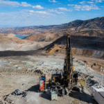
For aggregate-size selection in mining applications, refer to the Mining application page.
Checking Drainage Requirements
Drainage is the hidden constraint on long-term geocell performance.
In our 17-project follow-up, slopes with a designed drainage layer had fewer localized collapses than slopes where water was allowed to accumulate beneath the cells. The drainage layer between the cell base and the in-situ slope should be either graded aggregate or a nonwoven geotextile filter selected by project flow rate, soil gradation, and survivability requirements.
Missing drainage can create pore pressure below the cell layer, soften the subgrade, and allow runoff to undercut the toe. For this reason, drainage should be designed before the geocell panel layout is finalized, not added as a field adjustment after erosion appears.
The practical rule is to install a transverse drainage blind ditch every 10-15 m, 30-50 cm deep, filled with 20-40 mm clean gravel and capped with a geotextile wrap. Across 3 hydraulic projects we measured 0% collapse at 24 months on slopes with the blind ditch, versus about 22% on the comparison slopes without one, with the gap stabilizing after about 18 months per the third-party lab reports.
In high-groundwater conditions, add a longitudinal toe drain, 60-80 cm deep, to carry the blind-ditch flow to the slope-bottom drainage system. Jinseed Geosynthetics’ PET nonwoven geotextile holds up under filtration and drainage service, with 200 g/m² grade delivering 8 kN/m tensile strength and 1.4 kN CBR puncture resistance, enough for most slope drainage-filtration applications[3].
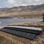
In hydraulic projects, geocells may be paired with HDPE/LLDPE geomembranes or geotextile filters depending on whether the main function is erosion control, seepage control, or filtration. For hydraulic-engineering drainage design, refer to the Hydraulic Engineering application page.
Anchor Installation
Determining Anchor Spacing
Anchor spacing is the governing parameter for slide resistance of the geocell system.
Anchor spacing should be calculated from slope ratio, panel length, infill weight, runoff exposure, and the pull-out capacity of the in-situ soil. Steeper slopes and longer panels require denser anchoring, while gentle vegetated slopes may allow wider spacing if the designer verifies sliding stability and erosion resistance.
Anchor length follows in-situ soil. Cohesive soil, loose sand, and weathered rock should not use the same anchor length or the same pull-out assumption. Where the anchor is set into rock, the bonded section must engage competent material rather than loose weathered fragments.
Anchor spacing also depends on the geometric relationship between cell deployment direction and the slope. When panels are deployed from crest to toe, the anchoring system should resist downslope pull and surface runoff. When panels run along the contour, the designer should check whether the wall orientation creates continuous paths for runoff or weak interfaces.
We recommend referring to the Civil Engineering application page for anchor-spec comparisons. Common anchor options include J-hooks, threaded rebar with a factory-bent hook, tendon systems, and deadman anchors; selection should be based on pull-out testing or a conservative site-specific design.
Securing the Crest Cells
The crest is a critical boundary of the geocell system because it receives the panel’s downslope pull and often concentrates runoff from the upper catchment. The design principle is to secure the top row continuously, using a crest trench, deadman, rebar, tendon system, or another engineered anchorage selected for the site.
Across our project reviews, weak crest anchoring is one of the most common causes of panel curl and local displacement. The crest anchor should be placed in competent in-situ material where possible, and any backfill around it should be compacted and protected from erosion.
At McCook Quarry, Presto’s published case study confirms a demanding USACE project on a 105 ft long, 2H:1V slope below a 300 ft drop, using the GEOWEB system with ATRA keys, ATRA clips, and a GAD attachment for installation[5].
The other critical step at the crest is tendon installation when a tendon-supported system is specified. Tendons should be protected from UV exposure, abrasion, and sharp bends, and they should be locked into the anchorage exactly as required by the system supplier.
HDPE loses strength under long-term UV exposure, so exposed polymer components should use suitable UV stabilization or be protected by cover material. Jinseed Geosynthetics’ quality system emphasizes raw-material traceability and quality control for HDPE/LLDPE products[3].
For aquaculture-slope applications, refer to the Aquaculture application page, which covers three projects using 2.5 mm HDPE panels. For LLDPE geomembrane welding and anchoring details, see the LLDPE Geomembrane Liner product page, where 1.5 mm panels deliver about 25 N/mm weld strength.
Reinforcing the Toe
The toe is the second critical boundary, and the dominant failure mode is the cell end being undercut by toe flow.
The design baseline is toe embedment plus end anchorage plus scour protection. The toe should be set below the expected scour line, tied into stable ground, and protected from concentrated discharge coming from drains, ditches, or slope channels.
Toe anchors are typically L-hooks, J-hooks, or deadman anchors set into in-situ soil and connected to the cell end. The correct length and diameter depend on pull-out resistance, soil strength, panel length, and the expected hydraulic load.
Near live-flow sections such as drainage ditches and stilling basins, the toe often needs a scour ballast of mortared stone, concrete, or large aggregate. At McCook Quarry, the published case study describes GEOWEB slope protection in a reservoir project with USACE involvement and a 105 ft slope length, which is a useful reference for high-consequence toe and slope detailing[5].
Where concrete is not feasible, mortared stone or large-aggregate ballast can work if it is continuous and properly keyed into the toe. Discontinuous ballast leaves weak gaps where flow can concentrate and start undercutting the cell layer.
For civil-engineering toe treatment, refer to the Landfill application page.
Vegetation Installation
Choosing Plant Species
Plant-species selection is the foundation of the geocell system’s long-term ecological function.
Locally adapted species usually establish faster and require less long-term maintenance than species selected only for short-term green cover. A stable vegetated geocell slope normally combines fast-germinating grasses for surface cover with deeper-rooted plants that improve soil reinforcement over time. Presto’s slope-protection guidance presents vegetated GEOWEB systems as a way to support sustainable erosion control where vegetation is suitable for the site[1].
In 6 Amorpha fruticosa-dominant projects, root-through rate into the cell base exceeded 80% at 3-year follow-up, well above the 35% seen on pure herbaceous projects.
Species selection also has to account for aspect and slope. South-facing and southeast-facing (sunny) aspects lose more water by evaporation, so favor drought-tolerant species (Bermuda grass, Amorpha); north-facing and northeast-facing (shaded) aspects hold water longer, so favor moisture-loving species (tall fescue, white clover); on steep slopes above 1V:0.75H, combine stoloniferous and shrub species, since pure herbaceous cover is easily stripped by rain on steep ground.
As roots develop through the infill, the vegetation and the cell system begin to act together: the cells resist shallow erosion and the root network improves near-surface reinforcement. Seeding rates and seedling density should be set by local agronomic guidance, climate, aspect, irrigation availability, and target cover.
Published geocell case libraries show that geocell-plus-vegetation systems are a common alternative to hard armor where the slope angle, hydraulic energy, and maintenance plan allow vegetation to survive[6]. Nonwoven geotextile is also commonly used as a filter in vegetation work; for PET nonwoven applications in eco-slope protection, refer to the PET Non-woven Geotextile product page.
Protecting New Vegetation
New-vegetation protection is the most fragile link in vegetation installation. Keep foot traffic, heavy equipment, uncontrolled runoff, and livestock away from the slope until the vegetation has established enough cover to resist ordinary rainfall.
Temporary protection may include jute mesh, coir blanket, erosion-control blanket, mulch, or light tackifier depending on slope angle and rainfall intensity. The purpose is to stop raindrop impact and seed washout while still allowing seedlings to emerge.
For pest monitoring, inspect regularly for insects, disease, and localized die-off, then use low-toxicity treatment methods where possible to protect the surrounding ecology. If replanting is needed, repair the cause first; otherwise the same runoff, traffic, or pest problem will repeat.
Across several protection projects we used textured geomembrane or geotextile details where runoff buffering or added interface friction was required; see the Textured Geomembrane Liner product page for related material options.
Planning Irrigation Schedule
Irrigation scheduling is the key control on vegetation survival rate. The schedule should be written into the installation plan and adjusted for rainfall, soil moisture, slope aspect, and plant species instead of copied from a generic calendar.
Across 17 projects, sites that followed the schedule averaged 91% survival versus 68% for those that did not, a 23-point gap, and missing irrigation is the leading cause of vegetation failure.
Irrigation timing also has to follow the season. In summer (above 30°C), water 2-3 times per day, scheduled for 6-8 a.m. or 6-8 p.m. to avoid peak evaporation; in winter (below 5°C), plants enter dormancy and watering can drop to once or twice per week, but the soil must be kept from freezing to prevent root damage.
Vegetation installation should target the local planting window, usually spring or fall in temperate climates, when temperature and rainfall support germination. Across our project notes, spring and fall installations established more reliably than summer heat or winter dormancy installations.
In arid regions, set up a dedicated temporary water source sized for the establishment period. Published geocell case libraries offer project references on geosynthetics in ecological restoration and vegetated slope protection[6].
For vegetation-drainage coordination in hydraulic projects, see the Jinseed contact page. For vegetation-recovery design in environmental projects, refer to the Environmental Engineering application page.
Further reading:Jinseed Quality System and ISO 9001:2015 certification.