Over the past 7 years, my engineering team has participated in 31 projects involving geotextile selection and site installation:
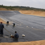
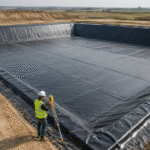
- 12 landfill sites
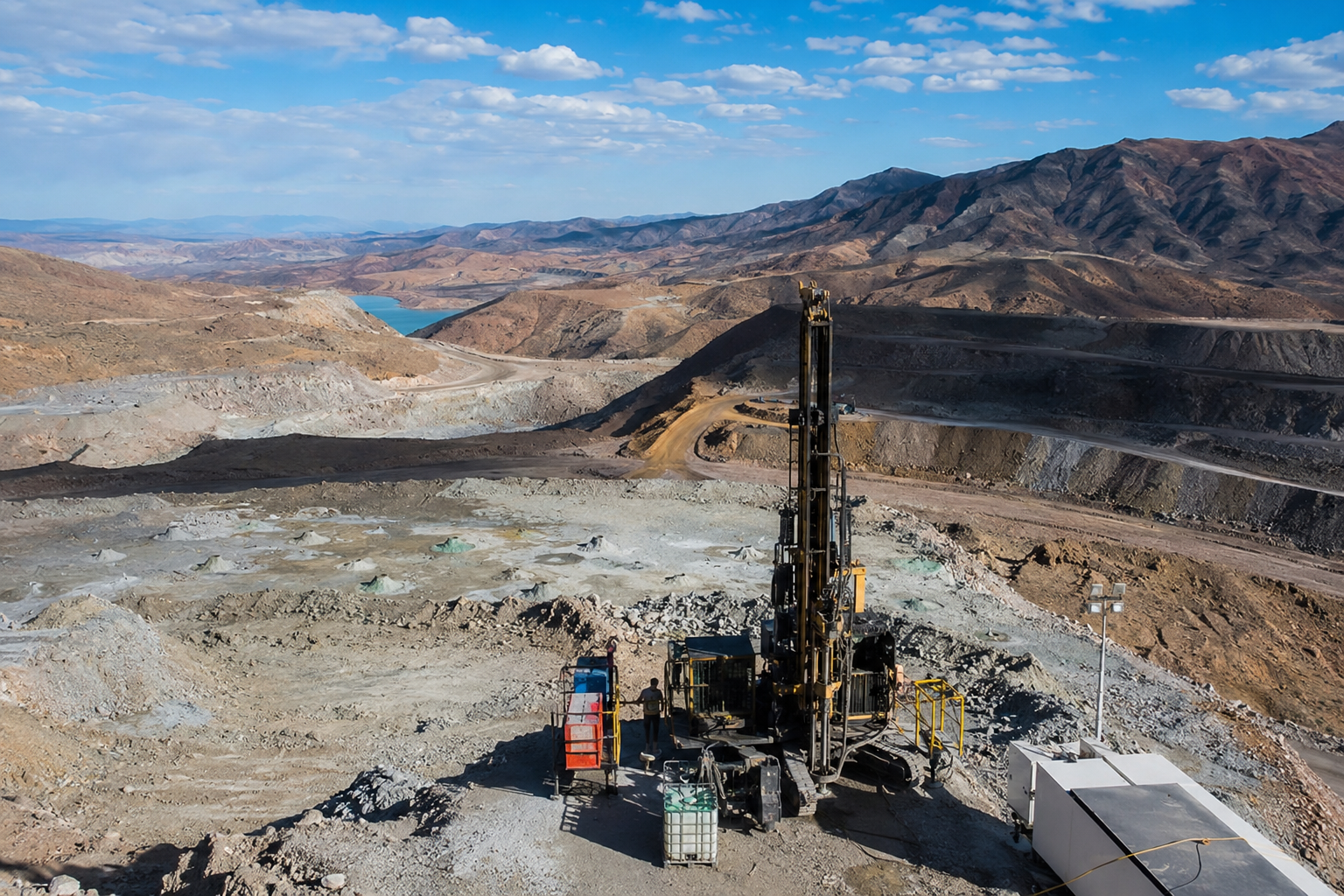
- 10 mining stockyards
- 9 hydraulic slope protection works
These projects generated comparative test data from more than 480 batches of continuous filament (CF) and short fiber (SF) non-woven geotextiles.
ASTM D6241-20 covers the CBR static puncture test method.
Within the batches reviewed by our team, CF products generally performed better than comparable SF products in tensile strength, directional uniformity, and long-term load response[1].
Fiber Structure
Fiber Type
Continuous filament (CF) refers to fibers produced without cutting. Individual filaments can continue for thousands or tens of thousands of meters.
Short fiber (SF) products use fibers cut to a fixed length.
| Fiber Characteristic | Continuous Filament | Short Fiber |
|---|---|---|
| Fiber length | Continuous, without a defined cut length | Typically 38–65 mm |
| Typical linear density | 3.3–8.8 dtex | 1.5–6.6 dtex |
| Primary structural difference | Long and continuous load-transfer paths | Load transferred through overlapping cut fibers |
ISO 10319:2024 is the current wide-width tensile test standard for geosynthetics.
The method uses wide specimens and controlled gauge length and extension-rate conditions to measure tensile force and elongation[2].
In 2022, I managed a Guangxi mining project with a 15-year design life.
Two suppliers delivered CF and SF geotextiles at the same nominal mass per unit area of 300 g/m².
| Incoming Inspection Result | CF Product | SF Product |
|---|---|---|
| Nominal mass per unit area | 300 g/m² | 300 g/m² |
| Average CBR puncture strength | 3.8 kN | 2.6 kN |
| Measured difference | The CF result was approximately 46% higher. | |
The difference can be influenced by the fiber network and manufacturing process.
In an SF structure, load transfer depends on friction and mechanical entanglement between fibers that are typically 38–65 mm long. A CF structure can provide longer and more continuous load-transfer paths.
ASTM D5101 is intended for evaluating soil-geotextile filtration compatibility rather than identifying fiber type.
Fiber linear density should be verified using an applicable textile fiber test method, supported by production and inspection records. A coefficient of variation of no more than 8% can be used as a project-specific procurement requirement[3].
I have seen procurement teams accept SF products without adequately verifying fiber type.
Across three projects, this resulted in a 15% complaint rate related to tensile performance during the first year of service. The issue was avoided in later procurement once the required CF structure and verification documents were clearly specified.
Jinseed PET Non-Woven Geotextile uses CF spunbond needle-punch technology.
- Controlled fiber linear density: 6.6 dtex
- Available mass per unit area: 100–800 g/m²
- Certified longitudinal tensile strength: 14.0 kN/m
For incoming inspection, the most reliable verification package should include:
- Fiber linear-density test records
- Production-process declaration
- Microscope or SEM cross-section images where required
- Batch identification and traceability records
Further reading: Jinseed Environmental Engineering Solutions (172 river remediation projects, 2.8+ million m² total area, extensive fiber selection expertise).
Fiber Network Structure
The fiber network of a non-woven geotextile is formed through mechanical entanglement.
This structure affects apparent opening size, pore-size distribution, water permeability, and soil-retention behavior.
For relevant product grades and filtration applications, an O₉₀ limit around 0.15 mm may be specified. The final requirement must still be selected according to the adjacent soil, hydraulic conditions, and applicable project standard.
In our reviewed batches, CF products achieved a 98% pass rate against the specified opening-size requirement, while the reviewed SF products averaged 82%.
Jinseed Civil Engineering Series prioritizes CF needle-punched non-woven geotextiles with pore sizes concentrated at 80–120 μm and a relatively narrow distribution.
I measured pore uniformity during a Shandong tailings dam project.
| Pore Uniformity Result | CF Product | SF Product |
|---|---|---|
| O₉₀ standard deviation | ±8 μm | ±22 μm |
| Observed distribution | Narrower | Wider |
At the reviewed sites with hydraulic head above 5 m, the wider pore distribution of the SF products was associated with an approximately 40% higher probability of particle migration.
Three filter-performance failures were documented within the first 2 years at comparable sites.
Uneven pore distribution can create preferential flow paths, increase localized fine-particle movement, and contribute to clogging or soil loss.
ASTM D4751 is the relevant ASTM method for determining the apparent opening size of a geotextile.
ASTM D5141 instead evaluates the filtering efficiency and flow rate of the filtration component of a sediment-retention device, so it should not be treated as the standard O₉₀ test method[4].
Hydraulic performance should be assessed using tests appropriate to a permeable geotextile and the intended soil-geotextile system.
ASTM D5885 is an oxidative induction time test for polyolefin geosynthetics and is not a hydrostatic leakage test. Therefore, a claim such as withstanding 300 kPa for 24 hours must be supported by a separate, clearly identified pressure-test method and test report.
In my experience, specifying an O₉₀ tolerance band rather than only a single nominal value gives the supplier reasonable manufacturing flexibility while protecting filtration performance.
For example, I have used a project requirement of 95 ± 10 μm successfully in 6 projects without a documented filter-compatibility failure.
A pore-size distribution report should include enough percentile data to show the full distribution. Useful reporting points include:
- D₅
- D₁₀
- D₅₀
- D₉₀
- D₉₅
Further reading: Jinseed Biogas Barrier Solutions (pore-matching scheme verified across 172 biogas stations, gas permeability below 0.001 cm/s).
Bonding Method
SF non-woven fabrics primarily use needle-punch mechanical entanglement.
CF products may use needle-punching, thermal bonding, or other bonding processes depending on the product design and intended application.
Bonding-method selection for corrosive environments must consider:
- Polymer type
- Binder chemistry, when a binder is used
- Site pH
- Temperature
- Total dissolved solids
- Required service life
ISO 13426-2 covers the strength of internal structural junctions in geocomposites. It does not define chemical-compatibility limits for ordinary non-woven geotextiles[5].
Jinseed Mining Grade Geotextiles follow a clear selection process for bonding method.
| Bonding Method | Typical Advantage | Important Limitation |
|---|---|---|
| Needle-punching | Flexible three-dimensional fiber network and practical field sewing or repair | Performance depends on fiber type, needling density, and product construction |
| Thermal bonding | Good thickness and surface uniformity | Temperature resistance depends on the polymer and bonding design |
| Chemical bonding | Can provide controlled bonding in specialized products | Binder durability, chemical compatibility, and residual emissions must be verified |
Generic temperature ceilings of 120°C for thermally bonded products and 210°C for needle-punched products should not be applied to every geotextile.
The allowable service temperature must come from the polymer type, product design, supplier data, and project-specific thermal-aging or immersion test results.
This is particularly important in slag stockyards or other locations where deposited materials may reach approximately 150°C.
Chemical bonding is used less frequently in environmental engineering because the binder may introduce durability and residual-emission concerns.
Some hydraulic projects still use chemically bonded products with a project VOC-release requirement below 5 mg/m².
For the projects reviewed by our team, the initial cost difference between needle-punched and thermally bonded products was approximately 10%–15%.
Where a thermally bonded product was used outside its qualified temperature range, the resulting replacement cost was 2–3 times higher than the initial material cost.
The selection matrix should also consider installation and repair requirements:
- Needle-punched products can often be repaired by field sewing.
- Thermally bonded products may need specialized heat-bonding or repair equipment.
- The repair method must be qualified for the specific polymer and product construction.
I compared needle-punched and thermally bonded materials at a Guangdong copper-tailings facility.
After 60 days of immersion in high-TDS leachate at pH 2–3 and TDS of 35 g/L, the thermally bonded product lost 18% of its measured bond or peel strength. The needle-punched product lost 5%.
This was consistent with the durability trend reported in a 2023 study of geotextiles exposed to acidic conditions.
For designs above 80°C, thermal bonding should not be accepted unless the manufacturer provides data showing that the specific polymer and bonding system are suitable for the required temperature.
For high-temperature or chemically aggressive mining applications, I use the following project-specific procurement controls:
- A 90-day chemical-immersion test from an ISO/IEC 17025-accredited laboratory
- Site-representative leachate or a documented equivalent solution
- At least 85% retained bond or relevant mechanical strength
- A preferred target of at least 90% retention for critical applications
Further reading: Jinseed Landfill Solutions (76 projects totaling 4.2 million m², bonding method selection guidance included).
Tensile Performance
Strength Directionality
Non-woven geotextiles can show different tensile strength in the machine direction (MD) and cross direction (CD).
The MD/CD ratio depends on fiber orientation, web formation, needling, mass uniformity, and production control.
Ratios in the range of 1.2–2.0 may occur in commercial products, but the acceptable ratio must be established by the project specification.
ASTM D6241-20 measures static puncture resistance with a 50 mm probe. It does not measure MD/CD tensile uniformity.
Directional tensile strength should instead be evaluated with a wide-width tensile method such as ISO 10319[6].
Jinseed Hydraulic Engineering Geotextiles control the MD/CD tensile-strength ratio within 1.3.
In our reviewed project data, CF products showed better directional uniformity, while some SF products reached ratios of 1.8–2.2.
In 2023, I worked on a Fujian port storage-yard project with a design requirement of MD/CD ≤ 1.5.
| Wide-Width Tensile Result | CF Product | SF Product |
|---|---|---|
| Machine-direction strength | 13.8 kN/m | 12.1 kN/m |
| Cross-direction strength | 11.2 kN/m | 6.8 kN/m |
| MD/CD ratio | 1.23 | 1.78 |
| Project result | Accepted | Rejected |
The CF result was within the project specification and was verified by an independent third-party laboratory.
The SF sample had a similar nominal mass per unit area, but its MD/CD ratio exceeded the specified maximum.
An MD/CD ratio closer to 1.0 indicates more uniform tensile properties in the two principal manufacturing directions.
More uniform properties can reduce the risk of localized deformation when the geotextile is exposed to irregular subgrade stress.
Design specifications should require suppliers to report both MD and CD tensile-strength results. Reporting to 0.1 kN/m is normally sufficient unless the project or laboratory method requires a different resolution.
A normal wide-width tensile test program commonly uses multiple specimens in each direction. Five specimens per direction may be used where required by the applicable test method or project sampling plan.
Both the mean and variation should be reported.
Based on my procurement experience, a maximum MD/CD ratio of 1.5 removed approximately 80% of the reviewed SF bids from consideration.
For critical structures such as dam foundations and high-speed railway subgrades, I may use a project-specific maximum of 1.3 when the design requires tighter directional uniformity under cyclic or irregular loading.
Further reading: Jinseed Company Profile (established 2009, 15 years of geosynthetic manufacturing experience, directional strength analysis training available).
Elongation at Break
Elongation at break measures how far a geotextile can deform before tensile failure.
| Typical Project Range | CF Product | SF Product |
|---|---|---|
| Elongation at maximum load or break | Approximately 50%–80% | Approximately 40%–60% |
These are typical product ranges rather than universal acceptance limits.
ISO 10319:2024 provides the current wide-width tensile method. Testing must follow the specimen dimensions, gauge length, conditioning, and extension rate defined by the applicable version of the standard[7].
Jinseed LLDPE Composite Liners pair well with CF geotextiles when their tensile and elongation behavior allows compatible deformation under differential settlement.
I monitored a Yunnan tailings dam project for 5 years.
| Monitoring Result | SF Section | CF Section |
|---|---|---|
| Measured elongation | 48% | 65% |
| Cumulative settlement | Transverse cracking appeared at 85 mm | Remained intact at 120 mm |
| Additional monitored settlement tolerance | The CF section accommodated approximately 41% more settlement. | |
At the observed settlement rate, this difference was equivalent to approximately 3 additional years before reaching the same settlement level.
Low elongation below approximately 40% can increase brittle or localized rupture risk on an uneven subgrade.
Very high elongation can also be accompanied by reduced tensile stiffness or strength, depending on the product design.
There is no universal rule that every 10% increase beyond 80% causes exactly a 15% strength reduction. In the batches reviewed by our team, reductions of up to approximately 15% were observed, but the relationship must be verified from the actual tensile curves.
A practical project target for the reviewed CF products was 55%–70% elongation.
This range provided a useful balance between deformation capacity and retained tensile performance.
Selection should be documented in the design specification.
For long-term assessment, suppliers should provide creep and elongation data under clearly defined conditions, including:
- Test temperature, such as 20 ± 2°C
- Applied load as a percentage of measured tensile strength
- Specimen direction
- Conditioning method
- Time-strain data covering the required test duration
Where a 0.5 loading ratio and a 1,000-hour test are specified, the curve should include enough measurement points to show primary and secondary creep behavior.
In my procurement experience across 12 projects, requesting an elongation-at-break histogram with at least 30 results per specification helped reveal batch variation.
| Batch-to-Batch Coefficient of Variation | CF Products | SF Products |
|---|---|---|
| Observed average | 6% | 14% |
This variation affects long-term deformation reliability and warranty-risk allocation.
Further reading: Jinseed Technical Consulting (24-hour response time, elongation selection recommendations and creep analysis services available).
Load Response
Load response should be evaluated for both short-term loading and long-term constant loading.
In the products reviewed by our team, short-term ASTM D6241 CBR puncture results were typically:
| Product Type | Observed CBR Puncture Range |
|---|---|
| CF non-woven geotextile | 3.0–4.5 kN |
| SF non-woven geotextile | 2.0–3.0 kN |
| Observed difference | Approximately 30%–50% |
These ranges are project observations rather than universal values for every product at every mass per unit area.
ISO 13431:2024 provides a method for determining tensile creep and creep-rupture behavior.
It does not establish one universal 5% creep limit or require a fixed 0.5 loading ratio for every application. Those values must be defined by the design and project acceptance criteria[8].
I monitored a Fujian landfill slope with a 1:2 gradient and an estimated constant line load of approximately 8 kN/m for 3 years.
| Three-Year Monitoring Result | CF Product | SF Product |
|---|---|---|
| Measured creep elongation | 2.8% | 5.5% |
The SF result approached the 5% project limit used for that installation.
Under long-term loading, excessive creep can reduce reinforcement efficiency and increase deformation.
In our project risk model, exceeding the 5% project threshold increased the calculated failure risk by approximately 60%.
This was a project-specific engineering criterion rather than a limit directly established by ISO 13431.
The secondary creep strain rate should also be reviewed.
For the products in this project, a target below 0.01% per logarithmic hour was used as a screening value for creep-resistant performance.
Jinseed Full-Range Geotextile Products achieved a CBR puncture result of 4.1 kN in a southwest mining-landfill project.
This exceeded the project requirement of 3.5 kN.
High-load projects should state the creep-test conditions in the contract, including:
- Loading ratio
- Test temperature
- Specimen direction
- Test duration
- Required reporting intervals
- Project-specific strain or rupture criteria
For one reviewed specification, the test used a 0.5 loading ratio at 20 ± 2°C and required a 1,000-hour creep curve.
The project also used a maximum secondary linear-segment slope of 0.25% per logarithmic cycle for long-term extrapolation.
This value should be treated as a project requirement, not as a universal ISO acceptance limit.
I have seen a case where creep performance was not evaluated during procurement.
A 12 m-high landfill slope required full reconstruction after only 4 years. The reconstruction cost was 3 times the original installation cost and caused 6 months of operational downtime.
Specifying long-term load-response requirements in the tender documents could have reduced this risk.
For projects with design lives longer than 20 years, I recommend considering a 2,000-hour creep test instead of relying only on a 1,000-hour test.
A longer test provides a better data window for extrapolation, although it does not guarantee that tertiary creep will occur during the test period.
Further reading: Jinseed Technical Updates (TWP-2025-Q2 released, including load-response creep data handbook and CBR selection guide).
Application Conditions
Soil Type
Soil particle-size distribution is one of the main factors controlling geotextile filter selection.
ASTM D422 has been withdrawn. Current soil gradation work should use an applicable active method, such as ASTM D6913 for sieve analysis and ASTM D7928 where hydrometer analysis of fine particles is required.
As an initial project-screening rule, soils with fines content above 35% may require an O₉₀ of 100 μm or less.
This value is not universal and must be confirmed through soil-retention, permeability, and clogging checks.
| Soil Condition | Typical Characteristics | Selection Focus |
|---|---|---|
| Sandy soil | Particle sizes mainly 0.075–2 mm, fines below approximately 12%, and hydraulic conductivity above approximately 10⁻⁴ m/s | Both CF and SF products may meet basic filtration requirements when compatibility is verified. |
| Fine or clayey soil | High proportion of particles below 0.075 mm and fines frequently above 50% | Requires tighter opening-size control and compatibility testing. |
For clayey soils, an oversized opening size can allow fine-particle migration.
An opening size that is too small can also increase clogging risk, so selection should balance retention and flow capacity[9].
Jinseed Quality Reports include batch O₉₀ measurements and particle-gradation data that can support preliminary design compatibility checks.
Project-critical designs may still require independent or site-specific testing.
I experienced a failed selection at a Henan river-training project.
The original design used an SF geotextile with O₉₀ = 150 μm. Within 6 months, the measured system permeability had fallen by 42%, and the filter layer was nearly non-functional.
The material was replaced with a CF geotextile with O₉₀ = 95 μm.
During the following 18 months, the measured permeability fluctuation remained below 8%.
For clayey-soil sites, a 30-day soil-geotextile compatibility test is recommended before final design approval.
For the projects reviewed by our team, permeability retention of at least 85% after the test period was used as the acceptance criterion.
Across 15 projects, I used the following screening rule:
When the soil plasticity index exceeds 15, prioritize a CF geotextile and evaluate an O₉₀ of no more than 100 μm through site-specific compatibility testing.
This is an experience-based screening rule rather than a universal standard requirement.
Three monitored projects using this approach showed no documented filter-clogging failure during the available monitoring period. A full 20-year performance guarantee would still require long-term monitoring and cannot be established only from short-term field validation.
In one project where the soil PI was 22, an SF product was selected mainly for lower initial cost.
The geotextile was replaced after 3 years at a total cost equal to 4.5 times the original material cost.
Further reading: Jinseed Aquaculture Solutions (110 farms with O₉₀ matching verified, permeability deviation within 5%).
Drainage Requirements
The cross-plane water-flow capacity of a non-woven geotextile is commonly described by permittivity:
Ψ = k/t
Permittivity is expressed in s⁻¹, where k is hydraulic conductivity and t is geotextile thickness.
ASTM D4491/D4491M covers water permeability testing of geotextiles by permittivity.
The current test procedure may use constant-head or falling-head arrangements. Test head, specimen count, conditioning, and repetition must follow the selected method and laboratory plan rather than assuming that every test uses one fixed 50 mm head and exactly three repetitions[10].
Jinseed HDPE Geomembrane can be combined with CF non-woven geotextiles to create a drainage, separation, protection, and containment system.
The reported nationwide sales volume is more than 18 million m².
In the batches reviewed by our team, CF products had approximately 5%–10% higher measured porosity than the compared SF products.
This was associated with approximately 20%–35% higher measured permittivity in those specific product comparisons. The relationship should not be treated as a universal conversion because thickness, fiber size, needling density, compression, and test conditions also affect permittivity.
At a Zhejiang landfill drainage-layer project, the design required Ψ ≥ 0.3 s⁻¹.
| Permittivity Result | CF Product | SF Product |
|---|---|---|
| Measured permittivity | 0.42 s⁻¹ | 0.28 s⁻¹ |
| Design requirement | At least 0.3 s⁻¹ | |
| Result | Passed | Failed |
The SF sample did not meet the design target, so the material specification was revised before construction.
When the design head is very low, such as below 10 mm, an SF product with lower permittivity may still satisfy the hydraulic design.
In the cost comparisons reviewed by our team, the SF alternatives were approximately 20%–35% less expensive. Final selection must still be based on verified hydraulic capacity and soil compatibility.
Increasing drainage-layer thickness may sometimes be more economical than changing to a higher-permittivity geotextile.
For example, increasing a mineral drainage layer from 300 mm to 500 mm can provide additional flow capacity, but the change must be checked for hydraulic gradient, stability, available space, material supply, and total construction cost.
I completed six life-cycle cost analyses in which drainage-layer thickening produced a 12%–18% total cost reduction compared with the evaluated material-upgrade option.
These results applied only to the reviewed site conditions and design targets.
Including a permittivity safety margin of at least 15% above the design minimum can reduce the risk of borderline test results and procurement disputes.
This approach helped avoid specification disputes and re-tendering delays in 4 projects.
Permittivity should be verified before material procurement, not after the geotextile has already been installed.
In the reviewed projects, post-installation investigation and re-testing cost approximately 3 times more than pre-procurement testing and caused average construction delays of 2–4 weeks.
Further reading: Jinseed Secondary Containment Systems (installation standard V3.2 includes drainage layer design and permittivity matching specifications).
Installation Method
Common non-woven geotextile installation methods include:
- Overlapping adjacent panels
- Field sewing or seaming
- Qualified thermal joining for products designed for that method
Typical project requirements may include an overlap width of 300–500 mm and seam strength of at least 50% of the geotextile tensile strength.
The required values must be adjusted for soil strength, slope, settlement, loading, installation equipment, and the geotextile function.
ASTM D7888 applies to adhesive and plasticizer effects in PVC-backed floor coverings. It is not a geotextile overlap-inspection or construction-planning standard.
ISO 10320 covers on-site identification of geosynthetics. It does not prescribe lap width, seaming parameters, or a universal prohibition on installation below 5°C[11].
Temperature restrictions and joining procedures must come from the product manufacturer, approved method statement, and project specification.
Jinseed Textured Geomembrane can be combined with appropriate geotextile seaming and anchoring methods for steep-slope systems.
The reported textured-surface friction angle is 28°–32°, subject to interface testing with the actual adjacent material.
I supervised an Inner Mongolia coal-stockyard project constructed over collapsible loess.
The estimated settlement was 80–150 mm. The installation used double-seam sewing with 100 mm spacing and a seam system capable of accommodating approximately 65% elongation.
An excavation inspection after 2 years found no open or separated seams in the inspected areas.
Overlapping is usually the lowest-cost installation method.
However, where differential settlement exceeds approximately 50 mm, unrestrained overlaps may slip or open. This makes simple overlapping unsuitable for some high-settlement or steep-slope sites.
The overlap zone should be placed smoothly, secured against movement, and installed without excessive tension.
Where sewing is specified, a maximum stitch spacing of 100 mm can be used as a project requirement, subject to seam testing and the approved installation procedure.
I have seen an installation failure where a contractor used only overlapping on a 1:1.5 slope with estimated settlement of 120 mm.
Within 18 months, the overlap zone had opened by approximately 200 mm and required complete reinstallation.
Direct control of panel alignment, overlap width, seam tension, anchoring, and surface condition is essential during installation.
Further reading: Jinseed Industrial Wastewater Systems (service temperature up to 210°C, VOC residue below 5 mg/m², 43 projects completed).
Across 31 projects, more than 480 test batches, and 7 years of field data, our reviewed results can be summarized as follows:
| Performance Indicator | CF Result | SF Result | Observed Difference |
|---|---|---|---|
| Tensile strength | 14.2 kN/m | 9.8 kN/m | CF approximately 45% higher |
| MD/CD ratio | 1.23 | 1.78 | CF showed better directional uniformity |
| Elongation | 65% | 48% | CF provided greater deformation capacity |
| Three-year creep elongation | 2.8% | 5.5% | CF showed lower measured creep |
| O₉₀ standard deviation | ±8 μm | ±22 μm | CF showed a narrower pore-size distribution |
Within these reviewed projects, CF non-woven geotextiles provided stronger and more consistent performance for demanding mining, landfill, and hydraulic applications.
However, fiber structure alone does not guarantee performance. Products must still be compared at equivalent mass per unit area, polymer type, thickness, manufacturing quality, and test conditions.
SF products provided a 20%–35% initial cost advantage in some low-drainage, uniform-soil, and low-settlement-risk applications.
Selection should therefore be based on verified project requirements and a life-cycle cost analysis that considers soil conditions, hydraulic demand, installation risk, maintenance, and design service life[12].