A tailings storage facility (TSF) failure’s impact is usually measured beyond the project boundary. The 2019 Brumadinho dam failure in Brazil released approximately 12 million cubic meters of tailings slurry and killed 270 people[1]; the 2015 Samarco failure released about 43.7 million cubic meters of iron tailings, contaminating about 680 km of waterways to the Atlantic Ocean[2].
These two accidents drove the International Council on Mining and Metals to emphasize documented design criteria, seepage management, monitoring, and risk-based containment in the GISTM 2020 standard; for high-consequence upstream TSFs, double-liner systems with leak detection are a common risk-control option rather than a universally mandated clause.
| Failure case | Released tailings | Main consequence |
|---|---|---|
| Brumadinho, 2019 | Approximately 12 million m³ | 270 deaths |
| Samarco, 2015 | About 43.7 million m³ | About 680 km of waterways contaminated |
Primary Geomembrane
Select the Membrane Material
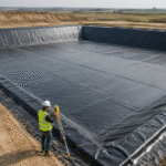
The primary geomembrane is the most critical physical barrier in a TSF liner system.
Material selection directly governs chemical resistance, long-term creep, and seam integrity. HDPE is commonly selected for mining containment because it combines chemical resistance, stress-crack resistance, weldability, and a mature specification framework under GRI GM13.
The GISTM 2020 global industry standard requires documented design criteria, risk controls, monitoring, and seepage-management considerations; HDPE-LLDPE double-liner systems are one practical construction option when the project consequence classification and seepage-control objectives justify it[3]. When the tailings contain cyanide, acidic drainage, sulfates, or heavy-metal leachate, the membrane selection should be confirmed by project-specific chemical compatibility testing.
LLDPE is softer with elongation up to 800%, fitting irregular settlement pond floors and oddly shaped side slopes; the specific parameters of LLDPE liners and HDPE liners can be reviewed in the manufacturer’s spec sheets.
When the slope is steep, a textured surface can improve interface friction compared with a smooth sheet, but the actual design value must come from project-specific interface shear testing against the adjacent geotextile, GCL, soil, or drainage geocomposite.
Textured geomembrane is very common in mining projects, with 30—45% higher sliding stability than smooth membranes.
For tailings containing oily leachate (such as oil-sand tailings) or hydrocarbon contamination, the chemical-resistance plan should be reviewed against project leachate chemistry and ASTM D5322 immersion procedures. HDPE shows swelling risk on short-term aromatic hydrocarbon contact, and a protective PET non-woven geotextile cushion of at least 600 g/m² is recommended.
ASTM D5322 specifies immersion procedures for evaluating the chemical resistance of geosynthetics to liquid wastes, leachates, or chemical solutions[5].
Determine the Membrane Thickness
Primary geomembrane thickness must be selected by load calculation, not by the “thicker is better” rule of thumb. The GRI GM13 standard lists 0.75, 1.0, 1.5, 2.0, 2.5, and 3.0 mm as common HDPE starting grades; Chinese tailings practice typically requires HDPE primary membrane of at least 1.5 mm, and many high-consequence mining specifications use at least 2.0 mm.
As dam height increases by 30 m, the puncture stress on the underlying geotextile increases significantly, so geomembrane thickness selection must combine dam height and stacking conditions.
Three common verification items for thickness selection:
- Puncture test (ASTM D4833) — a steel rod 8 mm in diameter pushed at 300 mm/min, measuring the breakthrough force, which should be at least 400 N for 1.5 mm HDPE
- Hydrostatic resistance (ASTM D751) — 1.5 mm HDPE is impermeable at 200 kPa water pressure
- Seam integrity (ASTM D6392) — hot-wedge shear strength should be at least 90% of parent material, peel strength at least 62%. When the substrate below the membrane contains sharp particles (such as crushed basalt), add a 600—1200 g/m² PET non-woven buffer layer, because the puncture protection from PET non-woven geotextile is non-negotiable under heavy stacking loads.
GRI GM13 provides property requirements for HDPE geomembranes, including thickness, tensile properties, stress-crack resistance, oxidative induction time, carbon black content, and dimensional stability. In high-load TSF applications, thickness selection should be checked against puncture protection, subgrade preparation, expected settlement, and construction survivability rather than selected from nominal thickness alone[6].
A comparison of reinforced vs. unreinforced liners shows that reinforced HDPE has 2.4× the tensile strength on steep slopes.
Check the Chemical Resistance
Chemical resistance is the central specification metric of the primary geomembrane, but many projects only read the “acid-alkali resistant” line and decide, which creates real blind spots.
Hazardous components in tailings leachate are far more complex than typical industrial wastewater: cyanide solutions, acidic drainage, heavy-metal complexes, and high-concentration sulfate can all affect the membrane system over the long term. Material selection should use project-specific chemical compatibility testing under ASTM D5322 rather than a generic acid-alkali claim[5].
Three things to do in practice:
- Take real tailings leachate (not lab-formulated liquid) from the mine, send it to a third party for a 90-day immersion test at the maximum operating pulp temperature
- Measure post-immersion tensile strength, elongation at break, and mass change, with each tolerance not exceeding 15%
- Test the chemical resistance of the seam zone as well as the parent sheet, because the welded heat-affected zone can become the controlling weakness if chemical exposure and welding conditions are not checked together.
For design comparisons, intact HDPE geomembranes are usually treated as effectively impermeable; field leakage is governed mainly by defects, seams, penetrations, interface contact, and drainage head rather than by a bulk hydraulic-conductivity value.
This means material grade should be controlled through GRI GM13 properties such as thickness, tensile behavior, stress-crack resistance, oxidative induction time, carbon black, and dimensional stability. A tailings leaching-process liner guide covers chemical-compatibility considerations for gold, copper, and nickel leaching processes[6].
Secondary Geomembrane
Define the Backup Role
The secondary geomembrane is the last physical barrier if the primary fails; its role is not to replace the primary but to “catch the leak.”
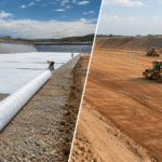
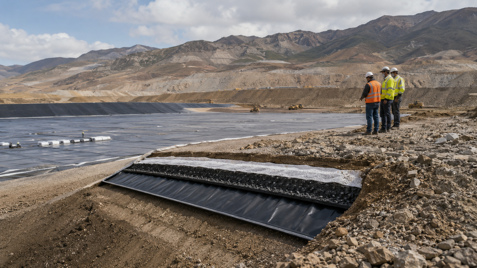
In a double-liner system, the secondary geomembrane sits below the leak detection layer. A typical top-to-bottom sequence is primary geomembrane + leak detection/drainage layer + secondary geomembrane + GCL, CCL, or prepared subgrade/protection layer[7].
The core value of the secondary membrane is to convert “possible leak” into “detectable, locatable, repairable” (response time from the first alarm to investigation is commonly designed in hours, not days). If the primary has a pinhole or seam defect, without the secondary the tailings leachate goes straight to groundwater; with the secondary, the leak is captured in the detection layer (typically a gravel drainage layer) between primary and secondary, and a flow meter and electrical sensor monitor the anomaly.
In practice, this system converts a hidden defect into a measurable flow or electrical signal that can be investigated before it becomes a groundwater issue. The tailings dam liner system construction includes the full secondary + detection layer assembly that maps one-to-one with this section’s selection logic[8].
Secondary membrane specification does not need to match the primary; a common practice is to size the secondary at 60—80% of the primary thickness, with a 25—30 year service life. For example, a 2.0 mm HDPE primary with a 1.5 mm LLDPE secondary saves material cost while keeping enough redundancy.
The key is not the absolute thickness of the secondary but how it cooperates with the primary—the two membrane weld seams should be staggered by at least 300 mm as a constructability and QA rule, not as a thickness multiplier. A landfill bottom liner system layers article includes a complete secondary + leachate-collection-layer diagram that can be referenced.
Coordinate the Layer Materials
The secondary geomembrane combination is not just “primary + secondary” but a four-layer system: primary + leak detection/drainage layer + secondary + GCL/CCL or geotextile protection, with each layer doing a different job. GCL (geosynthetic clay liner) typically has a hydraulic conductivity of about 5×10⁻⁹ cm/s or lower when fully hydrated, and it swells into a dense gel when wet.
CCL (compacted clay liner) at 60 cm thickness and a hydraulic conductivity of at most 1×10⁻⁷ cm/s is the EPA Subtitle D composite-liner benchmark for municipal solid-waste landfills; TSF designers may use it as a reference point, but mining containment still requires project-specific criteria[9].
Four-layer coordination rules:
- Primary carries the “absolute barrier,” requiring the highest grade (GRI GM13 certification + third-party test reports)
- Leak detection/drainage layer provides the measurable flow path between primary and secondary membranes
- Secondary (thickness 1.0—1.5 mm) carries the backup-containment role when the primary fails
- Geotextile (protection layer) carries “filtration + protection”—preventing sharp particles from puncturing the membrane while letting water through uniformly. In Jinseed’s tailings dam liner system documentation, the standard build is 1.5 mm textured HDPE + 4,800 g/m² GCL + 1.0 mm LLDPE + 600 g/m² PET protection geotextile, four layers totaling about 25 mm.
After major TSF failures, industry guidance has moved toward stronger governance, monitoring, and documented risk controls. When a double-liner system is selected, the value of the secondary membrane is that it creates a controlled space where leakage can be detected, collected, and investigated before it migrates outside the containment system[10].
Plan the Drainage Space
The drainage space between the secondary and the leak detection layer is the system’s “sensor”—once the primary leaks, the leak fluid is conducted to the detection sump or flow meter, triggering the alarm and locating the repair. This space is usually built with a 200—300 mm-thick gravel drainage layer (16—32 mm particle size) or a 5—6 mm-thick geonet, with at least 1% slope toward the collection sump.
Project specifications commonly set a high-permeability drainage path for clean gravel or geonet drainage spaces, so leak fluid reaches the detection sump quickly instead of building head on the secondary membrane[11].
Three easily overlooked details in drainage-space design:
- Collection-sump spacing — generally at most 150 m; longer spacing delays leak fluid travel time and slows repair
- Anti-clogging — cover the top of the drainage layer with a 200 g/m² geotextile filter to prevent fine tailings from entering and blocking the drainage channel
- Freeze protection — in cold regions, keep the detection path below the frost-sensitive zone or protect it with insulation, heat tracing, or another method approved by the designer so the alarm path does not freeze during winter operation.
The design principle is simple: each layer must carry a distinct function, and the failure of one layer should not immediately compromise the others. This is consistent with GISTM’s emphasis on risk controls, monitoring, surveillance, and documented design criteria for tailings facilities[3].
A landfill liner system shares much of its multi-layer construction logic with the TSF counterpart, although the design loads, chemistry, and consequence classification are different[12].
Leak Detection
Select the Detection Layer
The leak detection system (LDS) is the “visible eye” of a double-liner system, turning “possible leak” into a quantifiable, locatable, and response-ready metric.
Three mainstream methods:
- Electrical leak location (ELL) — electrode layers placed between primary and secondary membranes detect a leak-fluid-induced potential shift and can identify defects as small as a few millimeters on the liner grid
- Flow monitoring — a flow meter at the end of the drainage layer triggers an alarm when leak fluid exceeds a threshold, with 0.1 L/h precision
- Chemical tracer — a tracer is injected above the primary membrane, and the detection sump shows the tracer as the alarm. The three methods can be used alone or combined; the tailings dam liner leak detection is the key link in a double-liner system[8].
The engineering advantages of ELL are obvious:
- It can identify defects before enough liquid accumulates to create a measurable flow at the sump
- It can scan large liner areas efficiently when the surface condition and electrical setup are suitable
- Natural compatibility with double-liner systems—the electrode layer can be placed between primary and secondary membranes, and the result can be used to direct targeted repair and re-testing[13].
Flow monitoring fits scenarios where the primary leak is large (≥1 L/h); the strengths are simple structure and low cost, and the weakness is poor location accuracy (limited to within the collection-sump area). Chemical tracer fits R&D or high-risk projects (nuclear waste, highly toxic tailings), with inert tracers such as deuterated water or bromide.
ELL is strongest when it is treated as part of the construction QA and operations monitoring plan, not as a one-time final check. Geomembrane leak location services covers ELL, spark testing, and arc testing for integrity assurance[8].
Set the Drainage Slope
The slope of the leak detection layer (gravel drainage layer or geocomposite drain) determines both the leak-fluid evacuation speed and the detection sensitivity. Insufficient slope causes leak fluid to pool below the primary, generating false negatives (leak not detected); excessive slope risks geonet slip on side slopes.
Landfill leak-detection guidance commonly uses a positive drainage-layer slope toward the collection sump, often around 1% or higher where geometry allows. The exact slope and travel distance should be checked hydraulically for the selected gravel or geocomposite drainage layer[11].
Three common pitfalls in drainage slope design (failure rate around 25%):
- Local depressions — laser leveling every 10 m during construction; pooled water turns a “transient leak” into “long-term accumulation”
- Reverse slope on side slope — the top of the side slope must have at least 2% reverse slope (toward the slope top) to prevent slope runoff from backflowing into the drainage layer
- Sharp corners at turns — keep the drainage layer in a smooth arc at horizontal turns and avoid local low points that can trap leak fluid or stormwater.
GISTM 2020 does not prescribe one universal drainage-layer slope. Instead, it requires documented design criteria and risk controls, so the liner designer should state the selected drainage slope, hydraulic conductivity, sump spacing, and inspection method in the design basis report[3].
For a typical 60 m-wide mining cell, a 2% design slope gives 1.2 m of elevation difference across the width, and hydraulic engineering lining slope design can serve as an analog[7].
Plan the Inspection Access
The last step of the leak detection system (typically 8—10% of the project cost) is planning practical inspection access, an item often missed by design institutes. Inspection access includes:
- Detection-sump or flow-meter location — must have a paved road to the wellhead so the truck can drive right up
- ELL scan corridor — no stacking or secondary structures above the primary, with 1.5 m clearance during scanning
- Seam re-inspection corridor — critical seams (slope-to-floor interface, pipe penetrations) need 600 mm of working space
- Repair-material yard — reserve a protected storage area on site for compatible patch material, welding equipment, testing tools, and access to the relevant quality management system records.
Accessibility is the gold standard for inspection access:
- The detection-sump top elevation should be at least 1.5 m above the design flood level to avoid flooding
- The 3 m × 3 m area around the wellhead should be paved (concrete or 200 mm crushed stone), with a load-bearing capacity of at least 20 kPa for light-truck traffic
- Each detection sump should have reliable power and communication, with alarms, flow data, and inspection logs integrated into the site’s monitoring workflow where practical[10].
Major mining companies increasingly configure high-consequence TSFs with real-time monitoring, groundwater-protection monitoring, and documented surveillance workflows. This direction is consistent with GISTM 2020’s emphasis on monitoring, surveillance, and risk controls.
In TSFs equipped with double-liner + ELL + SCADA, routine inspection becomes more data-driven because alarms, flow data, and trend logs are centralized. The business case should compare up-front detection-system cost with avoided emergency repair, groundwater investigation, downtime, and regulatory risk.
Mining heap leach pad HDPE liners reflect the same logic end to end.