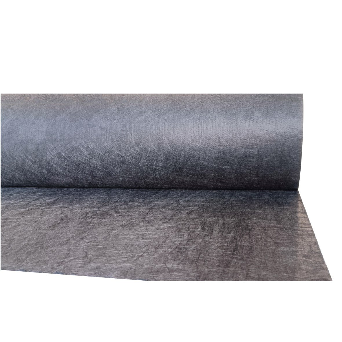
Geomembranes for mine heap leaching (commonly 1.5–2.0 mm HDPE) serve as the impermeable layer to prevent the leakage of cyanide, acidic, or heavy metal leaching solutions. High-quality solutions typically require a permeability coefficient ≤ 1×10⁻¹³ cm/s, working in conjunction with geotextiles, leachate collection layers, and weld seam testing to reduce the risk of groundwater contamination.
When selecting materials, focus should be placed on chemical corrosion resistance, puncture resistance, UV resistance, welding strength, and design life (commonly 15–30 years), making them suitable for the long-term stable operation of gold and copper mine heap leach pads.
Chemical Resistance & Durability
In heap leach pads, geomembranes are typically in continuous contact with acidic solutions (pH 1.5–3.0), saline process fluids, metal ions, and long-term hydrostatic pressure, with service lives often considered between 10–30 years. What truly matters is not just whether the material is called “HDPE,” but rather how much remains of its strength retention rate after chemical immersion, stress crack resistance time, oxidative induction time (OIT), and weld seam stability.
Chemical Compatibility
In heap leach liner systems, chemical compatibility is assessed by “contact medium + temperature + time” first, rather than thickness. Common process fluids at mine sites include sulfuric acid leaching solutions with pH 1.0–3.0, high-salinity solutions containing 50–150 g/L of total dissolved solids, circulating fluids containing metal ions such as iron, copper, aluminum, and nickel, as well as alkaline process fluids (pH 10–11) common in cyanide systems. A membrane that performs stably at 23°C does not necessarily maintain the same state at 40°C, 60°C, or during longer immersion cycles.
Breaking down the working conditions makes judgment easier. In terms of medium composition, acids, bases, salts, organic additives, oxidants, and metal ions may appear together; in terms of operating conditions, liquid temperature, liquid level, residence time, cycle frequency, exposure duration, and oxygen contact will overlap.
For example, in a copper mine heap leach pad where the operating temperature remains at 30–45°C for long periods and the solution contains sulfuric acid, sulfates, and polyvalent metal ions, the aging rate of the membrane under static immersion differs from its continuous contact on-site. Furthermore, if the liquid stagnates at the toe of a slope for a long time, local contact time may be 2–3 times higher than the design average, so compatibility judgment cannot rely solely on a single set of short-cycle experiments.
Many ask whether to use 1.5 mm or 2.0 mm first. This question usually comes later. Because even for the same 2.0 mm HDPE, differences in resin systems, antioxidant formulations, carbon black dispersion, and production stability will result in gaps in performance retention after immersion. Laboratories focus more on quantitative results than just “whether there is change”: tensile strength retention, elongation at break retention, mass change, volume change, hardness change, appearance change, and the magnitude of OIT decrease. A certain material may only show a mass change of ±1% after 90 days of immersion, but its elongation at break might have already dropped by 15–30%; while no problems are visible externally, the mechanical margin has already significantly decreased.
A more practical approach is to compare site fluids across three levels. The first level is the concentration of the main reagents, such as sulfuric acid at 10 g/L, 25 g/L, or 50 g/L; the second level is total dissolved solids and major salts, such as chlorides, sulfates, and nitrates; the third level is the metal ion load, such as typical ranges for iron, copper, aluminum, nickel, and zinc. As a medium changes from “low acid, high salt” to “medium acid, high metal ion,” the material absorption, hardening, surface changes, and long-term performance degradation curves will all vary.
If a project only uses deionized water or a single acid solution for compatibility testing, the reference value is limited and often far removed from actual heap leach fluids.
The following set of information is much more useful than “suitable for mining”:
| Inspection Item | Recommended Data | Approach Closer to Field Conditions |
|---|---|---|
| Medium Type | Acid/Base/High Salt/Metal Ions | Use actual project process fluid or simulated fluid |
| Immersion Temperature | 23°C, 40°C, 50°C, 60°C | Cover at least the common upper limit of site fluid temperature |
| Exposure Time | 30, 90, 180 days or longer | Select 2–3 cycles to observe change trends |
| Post-Immersion Testing | Tensile, Elongation, Mass Change, OIT | Test parent material and weld seams separately |
| Result Format | Absolute values + Retention rates | Do not just provide “Pass/Fail” |
Next, consider temperature. When polymers contact chemical media in liquids, molecular chain activity, additive migration, and oxidative consumption accelerate with every step increase in temperature. Heap leach fluids may stay below 20°C year-round in cold regions, while in arid regions, local liquid temperatures can approach 40°C during the day, and the surface temperature of black membranes can be even higher for short periods after solar radiation.
If experiments are only conducted at 23°C while the site is consistently at 35–45°C, that data only describes the ambient state and does not cover high-temperature contact periods. For projects requiring liner functionality after mine closure, compatibility data at longer durations and higher temperatures should be requested to infer service margins for over 10 or 20 years.
The following types of results are better for comparing different materials than just the material name:
- Whether tensile strength retention remains high after 90 days of immersion at 40°C
- How much elongation at break decreased after 180 days of immersion at 50°C
- How many minutes OIT decreased before and after immersion
- Whether mass change exceeds 1–2%
- Whether weld seam shear and peel results are close to the parent material’s degradation rate
- Whether there is surface hardening, swelling, whitening, cracking, or delamination
The “liquid contact mode” must also be included in the layout. In heap leach pads, three contact states vary greatly: continuous immersion, intermittent wetting, and local high-salt contact after evaporation. Continuous immersion is easier to evaluate; intermittent wetting subjects the material to repeated dry-wet cycles; after evaporation and concentration, local salinity may be higher than the average of the main fluid, and deposits can change surface conditions. If a slope or corner repeatedly undergoes the process of “daytime heating—liquid evaporation—nighttime re-wetting,” the material is not experiencing constant laboratory conditions.
The following comparison is better suited for screening during the selection phase:
| Field Conditions | Required Compatibility Content | Common Omissions |
|---|---|---|
| Low pH sulfuric acid leaching | Multi-temp immersion, long-cycle tensile and elongation retention | Only providing ambient data |
| Cyanide alkaline systems | Alkaline liquid + Salt + Metal ion combination testing | Only providing pure alkaline results |
| High salt circulating fluids | Mass change, hardening tendency, weld seam testing | Not testing weld seams |
| High temperature regions | OIT and long-term immersion at 40–60°C | Only testing at 23°C |
| Long-term retention post-closure | Trend data or inference basis exceeding 180 days | Only 30-day reports |
A reliable technical document will at least specify the sample number, medium composition, immersion temperature, immersion duration, specimen size, test standards, post-immersion items, and result expression. More detailed reports will provide raw values, averages, and deviation ranges for each data set. If a report only states “no significant effect” without any numerical values, it cannot support engineering judgment. For mine liners, a report containing 3 temperatures, 3 cycles, parent material + weld seam, and strength + elongation + OIT + mass change is far more valuable than a one-page promotional spec sheet.
Durability
In heap leach pads, geomembrane aging usually doesn’t show obvious damage within a year but begins with a decline in material margins. Project documents often state a design life of 10–30 years, but materials on-site endure several types of repetitive stress daily: daytime surface temperatures can reach 50–70°C and drop rapidly at night; process fluids stay at pH 1.5–3.0 or in cyanide systems; static loads from ore heaps are continuously applied to liners and welds; and local areas may experience overlapping settlement, wrinkles, and friction.
Many mining projects use 1.5 mm, 2.0 mm, or 2.5 mm HDPE geomembranes. Thickness affects puncture resistance and construction margins, but durability is not determined by thickness alone. For membranes of the same thickness, if one project has a long-term liquid temperature of 25°C and another is closer to 40°C, the antioxidant consumption rate will typically be significantly different. Common aging paths in engineering are not “holes first,” but rather surface hardening, reduced elongation capacity, local strain concentration, and performance degradation on both sides of the weld, which may subsequently develop into cracks or leaks.
First, look at the most easily overlooked internal part: the antioxidant system. Polyethylene geomembranes typically add primary and secondary antioxidants to delay thermal oxidative aging. Laboratories often use OIT (Oxidative Induction Time) to judge the antioxidant margin. When receiving a test report, do not just look at “Pass/Fail,” but also the initial value, residual value after aging, test temperature, and test method. In high-temperature conditions, the rate of OIT decline is often faster than under ambient exposure, and heap leach pads are not constant-temperature environments.
If a roll of membrane shows good data upon leaving the factory but is exposed to strong UV and thermal cycles for long periods after installation, the surface layer usually changes first. Outdoor exposure areas rely on carbon black to enhance UV resistance; the industry typically controls carbon black content within the 2.0–3.0% range and requires uniform dispersion. Poorly dispersed carbon black particles lead to inconsistent light and heat states on the membrane surface, potentially affecting subsequent aging rates. When reviewing documents, look for the carbon black dispersion grade rather than just accepting generalized claims like “added UV stabilizers.”
Durability issues often appear along paths of higher stress. Anchor zones at the top of slopes, weld transition points, edges of collection ditches, and uneven subgrade areas are locations prone to strain accumulation. Since HDPE material has a high modulus, environmental stress cracking is more concerning than simple tensile failure when subjected to constant tension and local constraints over time. The industry often uses tests like NCTL to evaluate stress crack resistance, with test times often expressed in hundreds of hours or longer.
Prioritize checking this set of information:
- Whether the design contact life is 10 years or 25 years
- Whether process fluid temperature is 20°C, 30°C, or 40°C+ year-round
- Whether there are long-term exposure zones, and if the exposure duration is 6 months or longer
- Whether slope height, length, and anchoring methods increase local tension
- Whether differential subgrade settlement might reach the centimeter level
- Whether the number and total length of weld seams reach thousands of meters
These items collectively affect durability. For instance, in an acid leaching project, if the liquid temperature is higher, the slope longer, and the liner exposure time longer, material margins will generally decline faster. If only ambient short-term test results are provided, the reference scope is narrow.
The thermal cycling of geomembranes also needs separate attention. During the day, the surface temperature of black HDPE membranes can be much higher than the air temperature due to solar radiation; as the temperature drops at night, the membrane will contract. In large-scale installations, this daily cycle repeatedly acts on anchor zones, weld zones, and wrinkle zones. If allowances are unreasonable during construction or large wrinkles form under high temperatures, subsequent ore/soil loading or liquid loading may form additional local tension. A single cycle has little impact, but the material performance will differ after hundreds to thousands of continuous cycles.
More attention should be paid to “performance retention” rather than initial limit values. For example, a set of parent material may have high elongation at break at the factory, but this doesn’t mean it will maintain that state after 90 days, 180 days of immersion or thermal aging. What is more relevant in long-term service is: tensile strength retention after immersion, elongation retention, puncture resistance changes, and weld shear and peel maintenance. When a material begins to age, strength sometimes doesn’t drop significantly, but ductility decreases first, making local strain concentration easier.
Durability can be broken down into 3 groups of checkpoints:
- Antioxidant Margin: Initial OIT, OIT after thermal aging, test conditions
- Cracking Resistance: NCTL time, notch sensitivity, long-term load conditions
- Outdoor Exposure Performance: Carbon black content, dispersion, UV exposure records
If a supplier can only provide conventional tensile, tear, thickness, and tolerances without long-term thermal aging or stress crack data, the judgment of late-stage service status will be weak.
When reading technical materials, separate “laboratory durability” from “system durability.” The former looks at how much performance the parent material itself retains in heat, oxygen, UV, and chemical fluids; the latter looks at what state is maintained once installed on-site, where materials, welds, protection layers, drainage layers, and subgrade flatness work together. Many engineering problems are not due to the material itself failing to meet standards, but rather a specific location in the system experiencing higher stress over several years, manifesting first.
This set of details is very useful during project audits:
- Whether the exposed membrane surface duration exceeds 3–6 months
- Whether the maximum operating temperature of process fluids approaches 35–45°C
- Whether the liner must be retained for more than 10 years after closure
- Whether there is secondary lining, double liners, or leak monitoring layers
- Whether the unit weight of the protective geotextile matches the membrane thickness
- Whether the drainage layer restricts the free deformation of the membrane surface
If leak monitoring data exists during the operation period, long-term trends should also be analyzed. Increased leakage does not necessarily come from new damage; it may also be related to original micro-defects gradually expanding in high-stress areas. Membrane aging, weld changes, subgrade settlement, and local punctures often do not appear in isolation but overlap.
Puncture Resistance & Mechanical Strength
In heap leach pads, geomembranes face not just static water pressure, but continuous compressive stress from ore particle angular points and stack heights over 20–100 m, local loads from construction vehicles, and minor subgrade settlement. Taking common 1.5–2.0 mm HDPE geomembranes as an example, selection cannot be based on thickness alone; one must simultaneously look at ASTM D4833 puncture strength, ASTM D6693 tensile properties, ASTM D1004 tear strength, and weld shear and peel strength.
Will it be punctured?
In a heap leach pad, physical damage to the geomembrane often first appears on the membrane surface’s local contact points rather than the weld seams. A 2.0 mm HDPE geomembrane laid on a well-prepared fine-grained subgrade will distribute stress; the same thickness of membrane falling on a subgrade containing 15–40 mm angular crushed stone will see pressure concentrate within a few millimeters after ore loading.
The membrane doesn’t “get pierced” instantly; a more common process is the formation of an indentation, followed by local stretching, then whitening and thinning, and finally forming a hole or tear after repeated pressure.
Think through the site stress sequence first. Below the geomembrane is the subgrade or prepared subbase; above is often a geotextile, drainage layer, ore load, and process solution. As the ore heap height increases, vertical stress is not evenly distributed across the entire membrane but transmitted along particle contact points. Even a single 8–12 mm sharp point in the subgrade protruding above the surrounding surface will cause the membrane to bear higher pressure at that spot. Add ore weight, construction tire pressure, and spreading impact, and local membrane strain will be significantly higher than surrounding areas.
Many only look at one puncture strength, such as ASTM D4833 index puncture. This is a starting point, not the whole story. This test uses a standard probe to press the membrane, which can compare the concentrated load resistance of different membranes, but it cannot fully replicate on-site particle shapes, contact angles, protection layer compression, and long-term static loads.
Engineering also references ASTM D6241 CBR puncture, as it is closer to the pressing state under thick layers of protective material. The former is like looking at the membrane’s reaction to “small-area sharp points,” while the latter is like looking at the bearing capacity under continuous loading from a “larger plunger.” Looking at both values together is closer to the usage scenario than looking at one number alone.
Place several variables affecting puncture in a single table:
| Variable | Common Range | Impact on Membrane Surface |
|---|---|---|
| Membrane Thickness | 1.5 / 2.0 / 2.5 mm | As thickness increases, there is more deformation space under local pressure |
| Subgrade Particle Size | 5–50 mm | The larger the grain size and sharper the edges, the fewer contact points and higher local stress |
| Geotextile Weight | 400–1200 g/m² | Higher weight usually provides stronger cushioning, but residual thickness after compression must be considered |
| First Lift Ore Thickness | 0.3–1.0 m | If unloading is too thin, impact is more easily transmitted to the liner system |
| Equip. Ground Pressure | Depends on equip/conditions | Turning, braking, and pivoting increase local membrane stress |
| Local Subgrade Settlement | mm to cm scale | Converts vertical compressive stress into additional tensile stress |
Every item in the table is not isolated. For example, a common misjudgment is “the subgrade is already compacted, so it’s fine.” High compaction doesn’t mean surface safety. If 10–20 mm angular particles remain after compaction and are not covered by a fine grading layer, the membrane will still form high stress at those points during subsequent loading.
Another misjudgment is “geotextile is already laid, so it won’t puncture.” If the geotextile is only 300–400 g/m², its thickness drops rapidly under load compression, and sharp points may still pass through the buffer layer to transmit the load to the membrane.
The following comparison is closer to daily projects:
| Site Conditions | Low Puncture Risk Presentation | High Puncture Risk Presentation |
|---|---|---|
| Subgrade Surface | Fine-grained, smooth, no obvious protrusions | Visible stone points, obvious local height differences |
| Protection Layer | Buffer layers on both top and bottom | Only partial protection or thin protection layer |
| First Lift Ore Loading | Gentle placement, layered, controlled thickness | Dumping coarse ore particles |
| Equipment Traffic | Defined routes, minimal traffic on membrane | Frequent rolling, turning, temporary parking |
| Drainage Layer | Controlled particle size gradation | Large particles with obvious angular edges |
This leads to the second point: on-site puncture is usually not a “single instantaneous action” but an accumulation of steps. The first step is the initial indentation from residual subgrade points or drainage particles; the second is continuous upper load slowly thinning the membrane at that spot; the third is additional displacement from uneven settlement or thermal expansion/contraction stretching the local thinned area; the fourth is process solution entering micro-cracks, further changing the stress state. By the time a leak is seen, the damage has often existed for a while; it didn’t just happen that day.
What is seen more in the field is “splitting after pressure damage,” not the “one-time piercing” imagined in laboratories.
If a project adopts 1.5 mm HDPE, subgrade treatment requirements are usually stricter; if the subgrade cannot be sufficiently refined or ore particles are coarse, the design often shifts to 2.0 mm or even higher thickness, while increasing the nonwoven geotextile weight. The reason is simple: as membrane thickness increases, more residual cross-section remains under local pressure; as the geotextile thickens, stress from contact points is distributed over a larger area on the membrane surface.
Can it withstand long-term stress?
In a heap leach pad, the geomembrane does not bear a one-time load but a state of high static load and local displacement that lasts months to years. For a 1.5–2.0 mm HDPE geomembrane, passing factory tensile, tear, and puncture data only means the material’s starting point is acceptable; in the field, it must face ore stacking height, slope self-weight, temperature cycles, weld residual stress, subgrade settlement, drainage layer particle contact, and the leaching environment.
First, look at the most basic layer: long-term stress and short-term stress are not the same thing. Common laboratory tensile tests, such as ASTM D6693, provide yield strength, break strength, yield elongation, and break elongation. Normal performance under short-term loading doesn’t mean the material stays the same after thousands of hours of continuous compression or tension. In a heap leach site, the upper ore height can reach 20 m, 40 m, or higher, and normal stress is not temporary but long-term.
Individual actions are not always high enough to exceed limits; the problem often lies in overlapping states. For a slope area, the membrane first bears the normal pressure of the upper cover, then is subjected to frictional dragging along the slope, then has a tendency to contract after cooling at night; if a weld happens to be in a geometric change zone, the local stress distribution will be much more complex than in a flat area.
In many projects, one hears first that “HDPE has high strength and sufficient elongation.” This is only half the story. Behavior before and after yielding is very different. Once the material enters yielding, local deformation becomes more obvious; if this position also has sharp point support, weld heat effects, or settlement differences, the membrane thickness will thin in a small area. Numerically, break elongation can reach hundreds of percent, but in engineering, no one wants the membrane to rely on “large deformation” during operation, because once strain concentrates in a narrow band, local section thinning happens quickly.
The table below is closer to site judgment logic:
| Stress Source | Common Duration | Common Location | What to Watch For |
|---|---|---|---|
| Ore Static Load | Months to years | Large pad bottom area | Whether stress can still be dispersed after protection layer compression |
| Slope Tension | Entire cycle | Slopes, toes, near anchor trenches | Interface friction, anchoring, weld layout |
| Temp Cycles | Daily, Seasonal | Exposed zones, edges | Additional displacement from expansion/contraction |
| Uneven Settlement | Gradual | Soft ground, fill/cut boundaries | Whether local suspension and additional tension form |
| Const. Residual Stress | Exists post-laying | Welds, corners, detail nodes | Whether initial stress overlaps with operating stress |
From here, we lead into weld seam issues. It’s easy to look at parent material and welds separately, but on-site they are a continuous system. For seams formed by dual-track hot wedge welding, both shear strength and peel strength must be observed. No matter how high the parent material’s tensile strength is, if the weld peel performance is weak, the seam may still be the first to fail under long-term displacement.
Especially in regions with strong sunlight and diurnal temperature differences reaching 15–25°C or higher, the membrane expands during the day and contracts at night, making stress cycles near the weld more obvious. If the temperature is high during laying and edge allowances are insufficient,接缝 and anchor zones are more likely to accumulate additional tension after nighttime contraction.
Many failures do not involve a “total break” but expand from small initial defects. For example, a shallow scratch 20–50 mm long may not seem to affect integrity initially; if it’s in a slope toe transition zone where subsequent pressure, tension, and bending coexist, it may become a larger tear. Similarly, a seam sample might pass conventional field tests during installation, but if asymmetrical stress exists on both sides of the weld, peel initiation points will slowly form after repeated temperature changes and minor displacements. When reading quality control documents, don’t just look at “Pass,” look at whether weld defects are concentrated at slope toes, corners, penetration areas, and repair patch edges.
Long-term stress also involves an often underestimated variable: the subgrade and foundation will not always maintain their initial shape. For a pad covering tens of thousands to hundreds of thousands of square meters, even with stable average construction quality, local areas may still experience differential settlement of several millimeters to centimeters. When the membrane crosses this settlement difference, it shifts from flat compression to a tensile state with bending. If the underlying drainage particles are coarse and the upper ore pile continues to apply pressure, the membrane will form additional strain when “bridging” the settlement zone. The settlement value itself may not be large, but if it occurs over a short distance, the strain gradient will increase significantly.
The following key points are useful in both design reviews and site inspections:
- Yield strength must be viewed separately from operating conditions; test limit values are not daily stress levels.
- High elongation at break does not mean it’s suitable for working in a high-strain state long-term.
- Seam shear and peel data should be viewed alongside the parent material.
- Stress near slope toes, anchor trenches, and pipe penetrations is more complex than in large flat areas.
- For every 10–20°C change in temperature, there is a perceptible change in membrane length.
- Local settlement concentrated over a short distance is harder to handle than uniform settlement.
Asking the question “Can it withstand long-term stress?” in detail usually comes down to two things: does the membrane have the capacity to maintain continuity under long-term static loads and displacement, and can the welds and details keep up with the parent material without destabilizing first? If any link—technical documentation, field installation, or operation monitoring—is missing, long-term performance will decouple from factory data.
Seam Integrity & Installation Reliability
Whether the seam is made stable is not a minor item; it affects later water leakage, repairs, and warranty. In this part, don’t just look at the material name; look at the seaming method, on-site welding or bonding inspections, corner and penetration details, and the re-inspection frequency after delivery. In Western roofing materials, many requirements are very detailed: for example, daily trial welds, full-line probe inspections, local repair widths, and semi-annual inspections.
How to make the seam
When looking at seams, put the “material name” aside for a moment and first confirm what method connects the two membranes into one. ASTM D4437/D4437M distinguishes field seams clearly, including common types like thermal fusion seams, hot air welding, hot wedge welding, extrusion welding, solvent bonding, adhesive seams, tape seams, and waterproof stitching. First distinguish between “heat welding” and “tape/adhesive”; then the methods for acceptance, re-inspection, and repair will not be misplaced. Heat welding focuses more on temperature, speed, and roller pressure; tape or adhesive focuses more on surface treatment, priming, compaction, and curing.
Even for single-ply membranes, a difference in seam formation means a whole different set of field control points. TPO and PVC are commonly done with hot air or hot wedge welding, where the surfaces of two membrane layers are heated to a melt state and then formed into a homogeneous connection by pressure; EPDM is commonly done with primer plus tape, or a pressure-sensitive splicing system, forming the splice by activating the surface and pressing together.
Carlisle’s EPDM splice data states that field SecurTAPE must be used with HP-250 or Low-VOC primer; Elevate’s QuickPrime Plus data also clarifies that primer is used to clean and activate the EPDM surface, which is part of the seam quality, not an incidental step.
Laying out the most easily compared dimensions and processes first makes reading much lighter:
| Item | Heat Weld TPO / PVC | Tape Splice EPDM |
|---|---|---|
| Seam Formation | Hot air, hot wedge, extrusion weld | Primer + Tape or splice adhesive |
| Field Focus | Temp, speed, roller pressure, weld width | Surface cleanliness, primer coverage, compaction |
| Common Materials | Same membrane, detail membrane, T-joint patch | 3 in. or 6 in. splice tape |
| Repair Method | Patch, cap membrane, re-weld | Re-clean, re-prime, add tape or patch |
| Highest Risk Areas | Start/stop points, T-joints, corners | Ends, contaminated surfaces, mechanical fastening zones |
There are two sets of numbers in the table worth remembering. Elevate’s QuickSeam Splice Tape data states that 76 mm (3 in.) tape is used for standard splices without mechanical fasteners through the seam, while 152 mm (6 in.) tape is used for methods with mechanical fastening in the middle; Carlisle’s Factory-Applied Tape also offers 3 in. and 6 in. widths.
Further, heat welding systems can’t just say they are “welded”; lap and patch details must also be checked. Sika’s applicator handbook states that common field lap widths are 5.5 in. (14 cm) and 7 in. (17.8 cm); GAF’s seam probing documents state that for minor repairs of thermoplastic membrane seams, T-Joint Cover Patches, UN-55 detailing membrane, or similar materials can be used, with the reinforced membrane cover width being at least 4 in. (102 mm) and heat-welded patches completed at corners.
How the seam is made depends not just on “welding” or “sticking,” but also on whether it’s completed in order. Sika’s manual details the sequence: welding trials must be done every morning before starting and in the afternoon; all seams must be probed after welding is completed; visual temperature indicators cannot replace daily cross-section weld test cuts; when judging if a weld is qualified, the membrane body should break first, not the weld seam. In plain language, at least 4 types of records should be left on-site: trial weld parameters, slice locations, probe inspections, and repair locations.
A short checklist of the most important on-site questions can be created:
- How many trial welds were done today—1 or 2+?
- Were welder temperature and speed recorded separately for morning and afternoon?
- Was full-line probing completed, or just sections?
- Were openings after slicing patched back and the locations marked?
- Were T-joints, pipe roots, drains, and corners photographed separately?
- Were contaminated or oxidized surfaces cleaned before welding or sticking?
- Are there secondary repair records for areas where equipment was added later?
Each of the above items can be found as corresponding actions in manufacturers’ installation or maintenance documents and are not extra additions. GAF also specifically reminds that probe re-inspection should be done at least 30 minutes after the weld has cooled; more attention should be paid to seam intersections, robotic welder stops and starts, and welds directly above insulation joints during inspection.
Seaming is also affected by weather and power conditions; seams made by the same equipment in the morning and afternoon are not necessarily the same. The Sika manual states that ambient temperature, wind, welder wheel weight, roller pressure, and power fluctuations all affect weld quality and width; the manual also provides a field tip: if the temperature indicator line doesn’t change normally within 5–10 seconds, stop to adjust the temperature or speed.
ASTM D4437/D4437M lists “hot air, hot wedge, extrusion, adhesive, tape” as different seam types; the same roof may have different seaming methods for different materials and details. Without separating the methods during acceptance, it’s easy to apply heat welding standards to tape splices, or vice versa.
Looking closer at details, seaming methods don’t just stay on large flat surfaces; many construction difficulties concentrate on T-junctions, corners, pipe roots, parapet wall upturns, and drains. GAF’s field guide table of contents separately lists T-Joint Cover Patch, preformed vent boot, inside corner, corner curb wrap, split pipe boot, scupper, and pourable sealer pocket, indicating that seaming is not just a “single line” but a whole connection system transitioning from flat to vertical.
To compress the reading further, the judgment order can be written as 3 sets of short points:
- First look at the seaming principle: heat weld, tape, adhesive, or hybrid.
- Then look at dimensions: lap width, tape width, patch width.
- Then look at records: trial weld, probe, slice, repair.
- Heat welding is more afraid of parameters not being readjusted.
- Tape is more afraid of the surface not being cleaned properly.
- Details are more afraid of having no matching accessories and relying only on field-cut material.
- Check start/stop points separately.
- Check patches at T-junctions.
- Check additional layer continuity at drains and equipment bases.
With these 3 sets of points, field conversations will be much smoother. Asking “was the lap done” usually gets a hollow answer; asking “is this seam heat-welded or tape, is the lap 5.5 in. or 7 in., and is the patch up to 4 in.” will get a much more specific answer.
One often overlooked item needs to be added: seam treatment for aged and contaminated surfaces. GAF’s seam cleaning data states that membrane surfaces affected by weathering or oxidation must be cleaned and, if necessary, lightly sanded before re-welding, then wait for the cleaner to evaporate; Elevate’s Splice Wash SW-100 data also states it is used to clean and prepare contaminated membrane surfaces so that subsequent priming, bonding, or welding meets requirements.
Is the installation reliable?
When looking at an installation, don’t just look at finished photos; look at whether verifiable construction records were left that day. In hot air welded membrane systems, manufacturer data usually requires trial welds every morning before starting; if weather, wind speed, or subgrade temperature changes, parameters must be recalibrated in the afternoon. Sika’s installation manual also writes that visual temperature indicators are not a substitute for slice inspections, and full-line probe inspections must still be done after welding, with the membrane body breaking first, not the weld seam.
Look first at the items most prone to field errors; many problems are not on the main surface but in the details. GAF data mentions that if local openings occur in thermoplastic membrane welds, the repair cover material width should be at least 4 inches (102 mm); T-joint cover patches should also be added at corners. Sika’s manual writes common lap widths as 5.5 inches (14 cm) or 7 inches (17.8 cm). During acceptance, a tape measure is more useful than verbal explanations: insufficient dimensions, whitening edges, unstable weld widths, and T-junctions without patches will all likely become repair points later.
To look more closely at “whether the installation is stable,” at least ask the following on-site:
- How many trial welds were done today—is there a record for both morning and afternoon?
- Was a full-line probe inspection done for main welds, not just sections?
- Are there photos/records of slice locations, quantities, and repair positions?
- Are there separate photos for T-joints, drains, pipe roots, and corners?
- Were welder temperature and speed readjusted for power fluctuations, wind, or low temperature?
- Did secondary contractors step on or cut the original membrane and then patch it back?
After looking at dimensions and inspection records, take a step further to see if the construction environment was treated seriously. GAF’s test welding document makes the variables affecting welds clear: air temperature, wind, and cloud cover changes all affect hot air welding; Sika also writes that welder wheel pressure, equipment speed, and power conditions will cause the same welder to produce different welds at different times. That is, trial weld parameters that pass at 9 AM cannot necessarily be copied at 2 PM.
Some only stare at whether the main surface is flat, missing the parts they should be looking at most. According to North American single-ply roof maintenance data, repairs are more concentrated at penetrations, terminations, drains, equipment bases, corners, and areas with added equipment because these locations bear thermal expansion/contraction, foot traffic, and concentrated water flow simultaneously. If there is standing water around a drain year-round, even if the weld only opens a few millimeters, the recurrence probability will be higher than in the middle of a slope. GAF’s seam probing document lists seams, T-joints, corners, and field damage in the inspection scope; following this will be more efficient than “scanning” from left to right.
The acceptance order can be compressed into a short table for easier field use:
| Acceptance Location | What to Look For | Common Abnormalities |
|---|---|---|
| Main Weld | Continuous weld, stable width, full-line probe | Open edges, missed welds, burn-through |
| T-joint | Patch added, edges compacted | Opening at T-junction |
| Pipe Root/Base | Rounded corners, complete additional layer | Wrinkles, hollowing, insufficient re-welding |
| Drain/Gutter | Low point treatment, lap direction, no debris | Long-term dampness, debris blockage |
| Metal Bar/Termination | Fixing spacing, edge sealing | Flaring, looseness, cracks |
Every item in the table can find a basis in manufacturer maintenance documents or construction detail drawings and is not improvised.
Add a set of very useful field checklist items—few words, but can filter out many installation problems:
- Does the color or gloss of the same weld change suddenly?
- Are there patched membranes around equipment supports, and are the edges rounded?
- Is the metal termination screw spacing uniform, and is any part loose?
- Were old membrane repair areas cleaned before welding, not just covered?
- After treating oxidized or weathered surfaces, was welding done after the cleaner evaporated?
- Are repair points marked on the roof plan for later tracking?
GAF’s seam cleaning document mentions that when the surface is already weathered/oxidized, it needs to be cleaned and lightly sanded, then treated with the corresponding cleaner, and welded after the solvent evaporates. If the front end is not handled well, the subsequent welding may look complete but might loosen from the edges within a few years.
Documents—not many, but complete. At least 6 types of materials should be collected: daily trial weld records, slice or peel records, repair point maps, detail photos, membrane batches, and warranty texts. Missing 2 or 3 of these will make checking problems very difficult later. Especially in multi-contractor projects, HVAC, electrical, and communication units often go on the roof after completion; without as-built point maps, it’s hard to distinguish if a scratch on the original membrane is an installation problem or later damage.
Re-inspection and Records
A seam that looks flat on the day it’s done doesn’t mean it will stay that way for 6 or 12 months. In North American single-ply roof maintenance data, the re-inspection frequency is clear: NRCA suggests checking at least twice a year, usually in spring and fall; add a special inspection after high winds, heavy rain, or hail. Treating the first acceptance as the last inspection breaks the information chain, leaving only surface phenomena and no timeline when investigating later leaks.
Re-inspection starts with the method, not just whether “someone went up to look.” GAF’s seam probing document requires thermoplastic membrane welds to cool for at least 30 minutes before probe re-inspection; during exploration, focus on seam intersections, welds above insulation joints, and locations where robotic welders stop and start. Checking too early might damage the weld bottom with the probe; checking too coarsely might find large openings but miss millimeter-scale edge separations.
Therefore, to see if a “seam is stable,” one can’t just ask the contractor “has it been checked.” A more useful approach is to break down the records: was there a trial weld that day, was there full-line probing after welding, are slice locations numbered, do repair points have photos, and can the next re-inspection return to the same seam by its original number? If 2 or 3 of these are missing, it’s hard to judge if the problem is an installation leftover, later foot traffic, or caused by a second equipment unit entering.
List the locations that should be focused on most during re-inspection to increase field efficiency:
- Full length of main welds, not just 2 or 3 sections
- T-joints, triple junctions
- Locations where automatic welders stop and start
- Welds directly above insulation board joints
- Drains, gutters, and low-point areas
- Pipe roots, bases, and termination bars
- Within 1 meter around added equipment
Following this order has an advantage: it sweeps through locations with more concentrated stress, larger temperature differences, and more foot traffic. Heat and speed change where automatic welders stop and start; support conditions are discontinuous above insulation board joints; areas around drains and gutters are prone to long-term dampness. When these 3 locations overlap, even if the weld edge only opens 2–3 mm, it is more likely to require repeated repair than the middle of a slope. Bringing as-built plans up on the roof usually halves the inspection time.
Further, it’s not just about “whether it was looked at,” but “how it was recorded.” Sika’s applicator handbook writes that daily cross-section weld test cuts should be made in welding quality control, and all seams must be probed; temperature indicators don’t replace slice inspections. That is, the records accepted by manufacturers are not just a few finished photos but a whole chain containing dates, weather, trial weld parameters, slice locations, and repair locations. If re-inspection doesn’t connect to this chain, many abnormalities will only be memories by the second year of roof use.
In practice, records are best divided into 3 groups rather than mixed in one table:
- Daily construction records: Temperature, wind, welder temp, speed, trial weld count
- Daily quality records: Probe inspections, slice numbers, repair segment lengths, patch locations
- Subsequent inspection records: Inspection date, weather, defect photos, re-test results, recurrence
Grouping this way makes the timeline clear. A common case: the 1st inspection finds a weld edge opening 5 mm, which reappears in the same spot 6 months after repair. If there was no record of whether this seam was an automatic welder stop point, or the wind speed and slice results for that day, it’s hard to judge if it was insufficient heat at the start or caused by repeated foot traffic during equipment maintenance.
Field layouts can be kept light without long tables. “Number + Photo + Short Note” is most practical:
- Number: e.g., S-12, T-04, D-03
- Photos: 1 wide shot, 1 close-up
- Location: Write by grid or axis
- Length: How long the opening is (cm or in.)
- Status: Untreated / Repaired / Continue to observe
- Next re-inspection date: 30 days, 6 months, or 12 months
One A4 page can hold 20–30 points. Following the numbers during later inspections is much easier than finding problems across the entire roof again. NRCA’s single-ply maintenance materials emphasize that inspection, maintenance, and emergency repair should be linked; records are not incidental documents but the map for subsequent inspections.
Re-inspection frequency shouldn’t just be hollow phrases like “check regularly.” A more common and executable schedule is: look once 30 days after delivery to confirm if construction leftovers are patched; look once at 6 months, focusing on drains, equipment areas, corners, and metal terminations; look again at 12 months to compare repair points within a year to original records. Then continue with NRCA’s twice-yearly schedule, adding one after storms. Clearing up months and triggers prevents later delays.
Next, regarding probe re-inspection itself, many just “poke around” without judging by position. GAF documents mention that seam intersections, robotic welder stops and starts, and parts where heat welds cross insulation joints need extra attention. From a different perspective: don’t distribute the same 20 minutes of inspection time evenly. Spending 60% of the time on details that may account for less than 20% of the length actually increases the probability of finding problems.
To avoid re-inspection being just surface descriptions, abnormalities can be divided into 5 categories for faster writing:
- Edge opening: Edge detached; record length and maximum width
- Missed weld: Local non-fusion; record location and continuous length
- Burn: Surface overheated; record if penetrated
- Wrinkle: Record if crossing a weld
- Secondary damage: Cuts, drags, foot traffic marks from equipment maintenance
Each category corresponds to a treatment method and is easy to tally later. For example, if more than 8 cases of “secondary damage” appear on the same roof within 12 months, the problem is more likely roof traffic management than original welding parameters.


Leave a reply