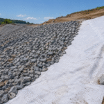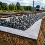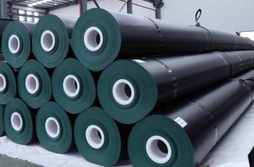
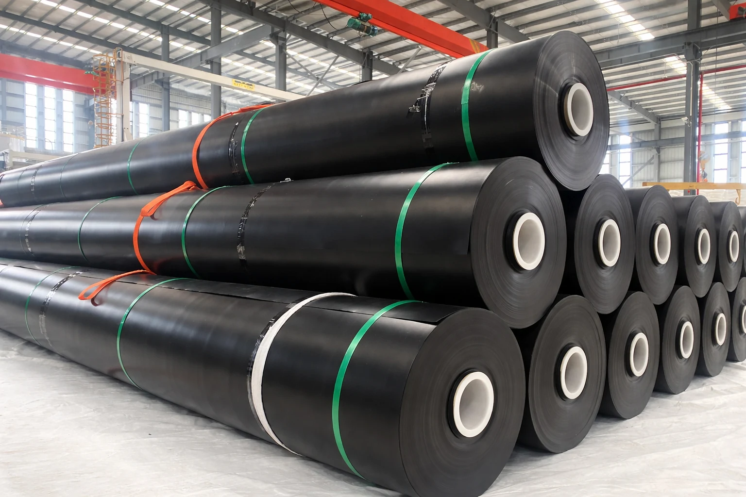
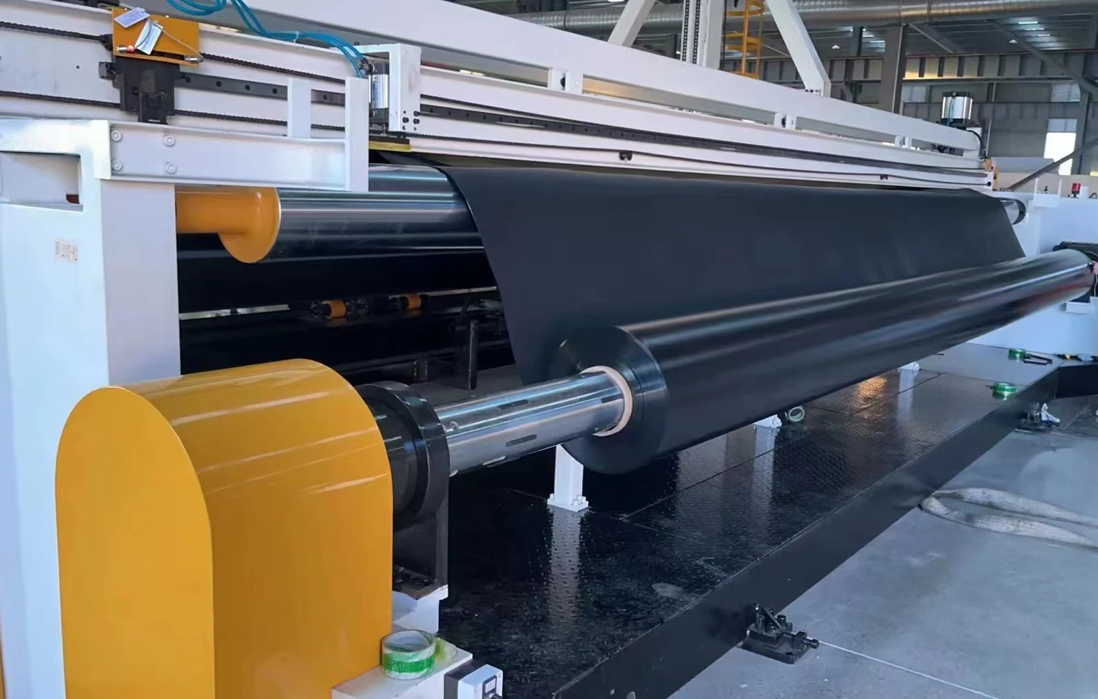
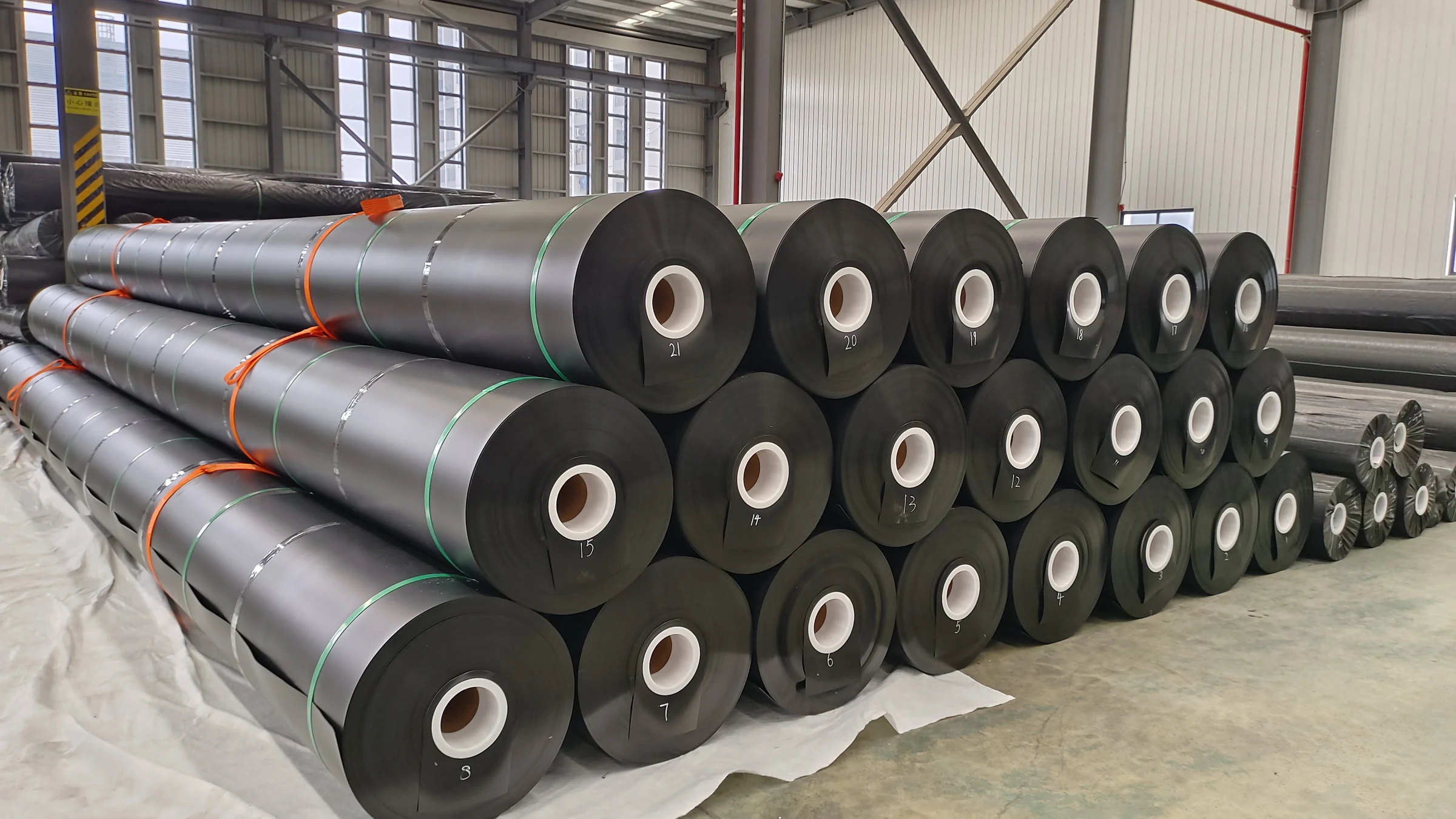
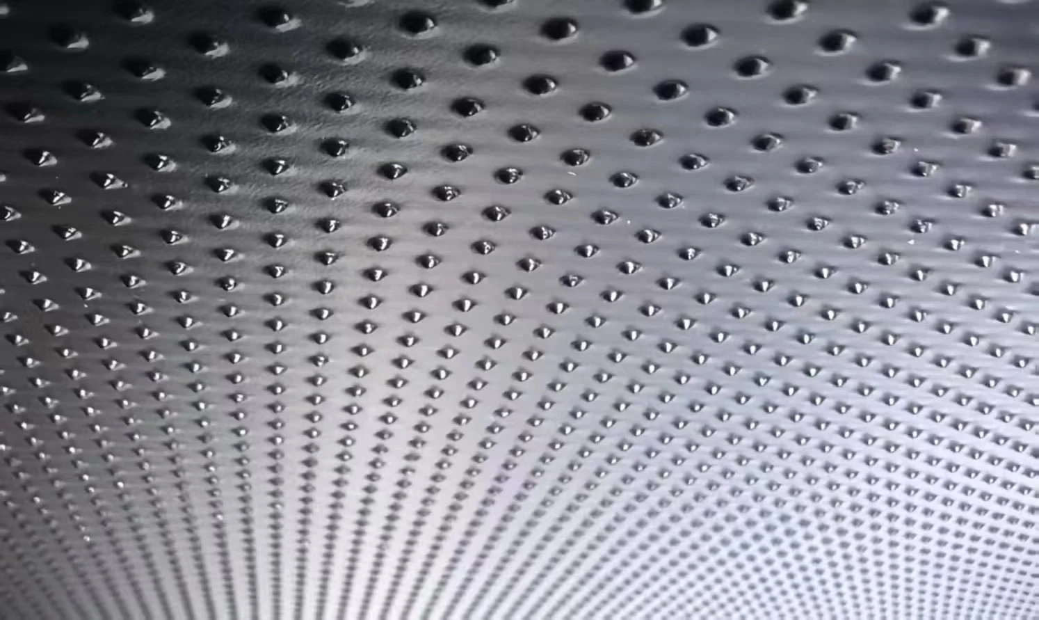
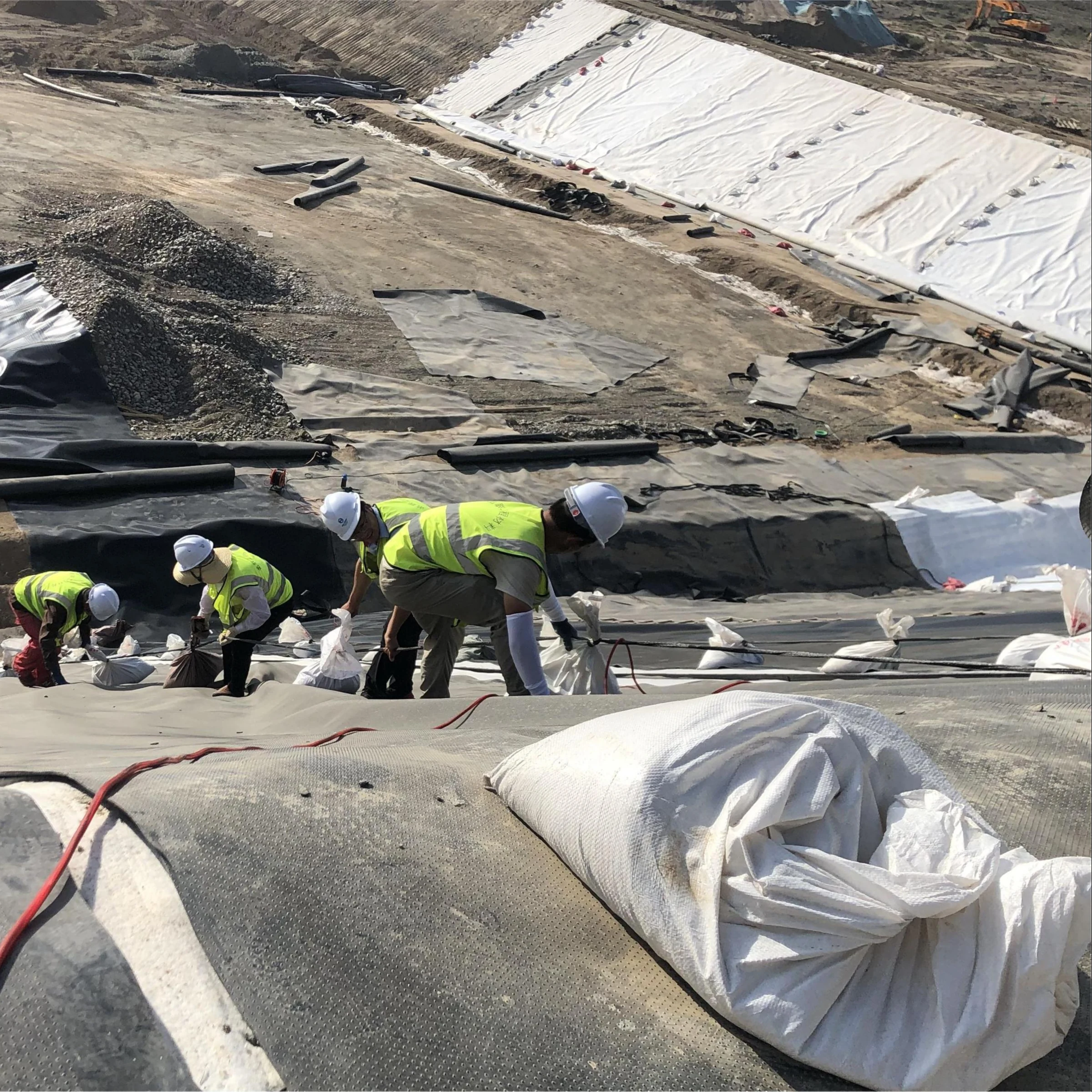
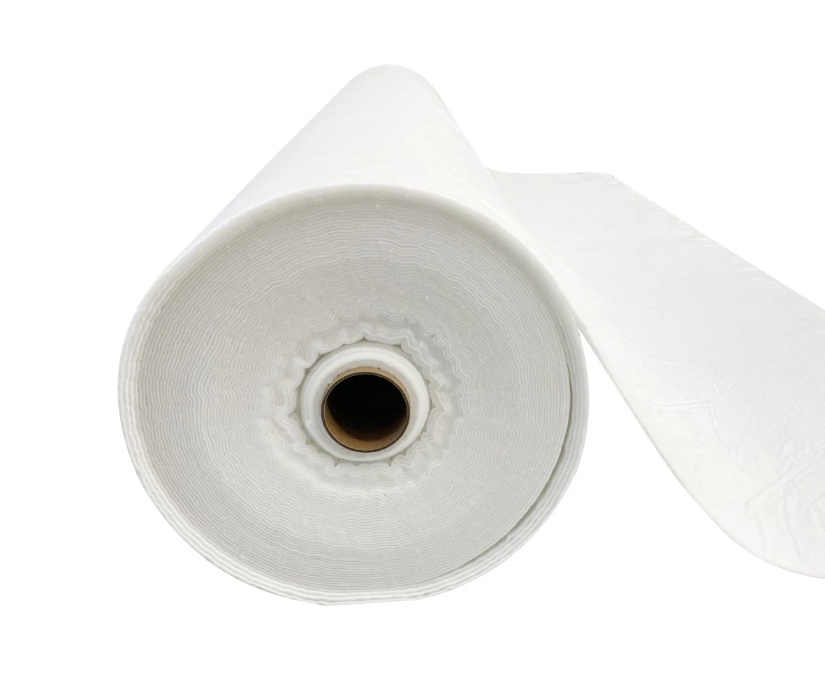

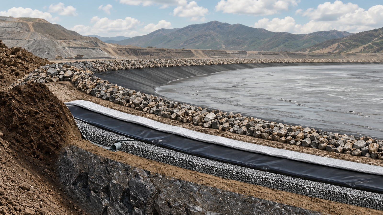
A tailings dam lining system has three connected functions: control seepage, collect and drain water, and protect the barrier from damage. HDPE geomembrane can provide the barrier, but its performance depends on the foundation, seams, drainage outlets, interfaces and protection layers. Selecting a membrane thickness alone does not establish dam safety.
This guide explains the information needed to specify those three functions. Numerical examples are identified as calculations, not verified Jinseed project results. Final design must address the facility’s tailings, foundation, water balance, loading history, consequence classification and applicable approvals. The Global Industry Standard on Tailings Management provides a broader framework for lifecycle management; it is not a universal liner cross-section or a substitute for local requirements.
1. Seepage control: define the barrier and its operating conditions
| Function | Possible components | Design question |
|---|---|---|
| Containment | Geomembrane, with a compatible GCL or compacted soil barrier where specified | What leakage performance, deformation capacity and chemical resistance are required? |
| Water collection | Granular drains, drainage geocomposites, collection pipes and accessible sumps | Which water is being collected, and where can it safely discharge? |
| Protection | Prepared foundation, cushioning geotextile and selected cover material | Will the complete assembly survive aggregate contact, construction and long-term loading? |
Select HDPE thickness from loading and compatibility, not pH alone
Provide the membrane supplier and designer with the tailings particle-size distribution, angularity, placement method, maximum overburden, expected settlement, slope geometry and process-water composition. A pH value omits temperature, dissolved salts, oxidants and other constituents that may affect a lining system. Neither “acidic tailings require 2 mm” nor “neutral tailings need only 1 mm” is a sufficient selection rule.
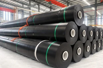
GRI-GM13 Revision 19 covers material properties for HDPE geomembranes. For its 1.5 mm smooth material, the minimum average thickness is 1.5 mm and the individual minimum is 1.35 mm. Those are material acceptance values, not proof that 1.5 mm is suitable for a particular tailings facility. Carbon black content of 2.0–3.0% is another specified property; it does not establish a guaranteed outdoor service life.
Use an exposure program representative of the actual process liquid and temperature. ASTM D5322 addresses laboratory immersion procedures, while ASTM D5747/D5747M addresses tests used to evaluate geomembrane chemical resistance. Define which changes in mass, dimensions and mechanical properties are acceptable before testing. A short immersion result cannot by itself substantiate decades of service.
Decide whether a composite or double liner is required
A geomembrane in close contact with a low-permeability soil layer or GCL forms a different system from two geomembranes separated by a drainage layer. The latter may provide an interliner collection and monitoring zone. Specify each layer’s function and keep clean groundwater drainage separate from contaminated seepage collection where the design requires it. The collection zone must have a defined outlet and monitoring arrangement; its existence alone does not locate a defect.
Do not prescribe a 6 mm GCL or 500 mm clay layer for every dam. A GCL’s hydraulic response depends on hydration, confinement and solution chemistry. ASTM D6766 addresses GCL hydraulic performance with potentially incompatible aqueous solutions. A distilled-water index result is not automatically applicable to saline or chemically aggressive tailings water.
On slopes, test the actual interfaces and GCL internal shear behavior at relevant normal stresses and conditioning. ASTM D6243/D6243M addresses GCL internal and interface shear resistance. “Textured HDPE” is not a guaranteed 30° interface friction angle. The governing weak interface, settlement and anchorage must be evaluated together.
Report seepage measurements with the correct units
Hydraulic conductivity, flux and collected leakage are different quantities. Conductivity k is reported in m/s; flux is flow divided by area; collection-system flow is commonly reported in L/day or m³/day. For porous media, Darcy flux also depends on hydraulic gradient. Leakage through a geomembrane defect depends on defect geometry, liquid head and the underlying contact conditions; it should not be inferred from an unexplained “equivalent conductivity.”
Illustrative conversion: 0.08 L/day/m² over 85,000 m² equals 6,800 L/day, or 6.8 m³/day. The corresponding area-normalized flux is approximately 9.26 × 10⁻¹⁰ m/s. This is not the material’s hydraulic conductivity and is not a regulatory acceptance limit.
Tracer interpretation also requires distance and a defined arrival criterion. A hypothetical 40 m path traversed in 18 hours gives an apparent travel velocity of 6.17 × 10⁻⁴ m/s. By contrast, 2.3 × 10⁻⁸ m/s over 18 hours corresponds to only 1.49 mm. Dispersion, preferential flow and uncertain path length prevent either number from becoming a direct permeability measurement. Tracer selection and introduction require an approved investigation plan.
2. Drainage: separate capacity, filtration and pressure control
Specify capacity under the expected stress
A drain above the barrier, a leak-collection layer between barriers and a groundwater underdrain have different duties. Identify each on the drawings. Above-liner drainage may collect process water; groundwater underdrainage may reduce external head; neither should be connected indiscriminately to the other. Evaluate blockage, pump failure, changing tailings deposition and closure conditions.
For a drainage geocomposite, use flow per unit width or transmissivity measured with representative normal stress, gradient and contact materials. ASTM D4716/D4716M provides an in-plane flow test. A nominal 5 mm core or an unconfined permeability value does not establish long-term capacity under a tailings load. The design must account for compression, creep, soil intrusion and clogging using product- and site-relevant evidence.
Illustrative demand: 450 m³/day requires an average continuous flow of 18.75 m³/h. One pump delivering 20 m³/h at the actual operating head would provide only 1.25 m³/h above that average. A standby pump improves redundancy but does not make the normal duty capacity 40 m³/h. Peak inflow, usable sump storage, maintenance and power outages still need to be checked. A 50 m³ usable sump would fill in about 2.67 hours at 18.75 m³/h if pumping stopped and inflow stayed constant.
Match pipes and filters to the actual flows and particles
Choose pipe diameter from the hydraulic profile, inflow distribution, outlet conditions, allowable head and structural loading. Catchment area alone cannot establish whether DN100, DN150 or DN200 is adequate. Perforations and the surrounding filter need compatible gradations so the drain can collect water without progressively importing tailings fines. Provide accessible inspection or cleaning points, with the method and pressure limits agreed for the installed pipe system.
Filter opening size, water flow and resistance to clogging must be considered together. Do not substitute geotextile mass for filtration testing, or assume the smallest opening is always best. Freezing conditions require site frost-depth and thermal assessment; a fixed insulation thickness cannot guarantee an above-freezing outlet temperature at every facility.
Use pore-pressure monitoring to test design assumptions
Effective stress is reduced when pore-water pressure rises at a given total stress. Instrument locations should therefore follow the geotechnical model and credible failure mechanisms, rather than an automatic layout at one-third and two-thirds of dam height. Record instrument elevations, calibration, baseline conditions and trends alongside deposition and rainfall.
For arithmetic context, a 0–300 kPa instrument rated at ±0.25% of full scale has a nominal accuracy band of ±0.75 kPa. That specification does not include every source of installed-system error, and it does not define the alarm threshold. The facility’s Trigger Action Response Plan should state the site-specific trigger, responsible person, verification step and response.
Prefabricated vertical drains require a separate consolidation and stability assessment. As a geometry check, 2,400 drains over 18,000 m² represent 7.5 m² per drain, approximately 2.74 m square-grid spacing before boundary effects. This cannot simultaneously describe a uniform 1.0–1.5 m grid over the same area. No percentage of pore-pressure dissipation in 60 days can be promised from drain dimensions alone.
3. Geomembrane protection and construction quality
Evaluate the full protection assembly
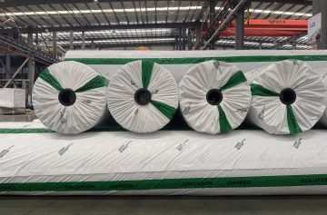
A cushioning nonwoven geotextile should be selected against the aggregate, foundation, placement method and expected load. Mass per unit area is useful for identification, but two 400 g/m² products need not provide identical puncture protection. ASTM D6241 is a static puncture index test; ASTM D5514/D5514M provides large-scale hydrostatic puncture methods, including site-specific configurations. Distinguish an index result from a demonstration that the installed assembly protects the membrane.
Prepare and inspect the foundation, manage wrinkles and exposed edges, and place the approved cover without trafficking directly on unprotected geosynthetics. The construction plan should specify lift thickness, equipment, placement direction, repairs and hold points. Do not treat a fabric’s index puncture force as a universal allowable excavator contact pressure.
Separate welding settings from acceptance requirements
Wedge temperature, speed and pressure are equipment and field variables. Establish them through trial seams and reassess when material or conditions change. A published temperature range is not an acceptance test. Use the manufacturer’s approved surface preparation for extrusion repairs rather than prescribing a solvent for every HDPE product.
GRI-GM19a Revision 10, Table 1(b) gives the following laboratory seam-strength reference values for 1.5 mm nonreinforced HDPE. The project must adopt the applicable specification and evaluate its other requirements, including peel separation and break behavior.
| Seam test | Table value | Equivalent per unit width |
|---|---|---|
| Hot-wedge or extrusion seam shear | 525 N/25 mm | 21.0 N/mm |
| Hot-wedge peel | 398 N/25 mm | 15.92 N/mm |
| Extrusion-fillet peel | 340 N/25 mm | 13.6 N/mm |
A reported 11.2 N/mm shear result would be below the 21.0 N/mm reference, even if it exceeded a weaker procurement number. Acceptance cannot be based on a favorable percentage of parent-sheet tensile strength alone. GM19a does not set one universal field sampling interval; the engineer and construction quality assurance plan establish the sampling and retest process.
Use ASTM D6392 for destructive evaluation of nonreinforced thermofused geomembrane seams, with the specified acceptance criteria. Combine the appropriate nondestructive seam checks with mapped repairs and, where specified, an electrical leak-location survey. These checks address different defect types and do not replace one another.
Documents to request before accepting a tailings lining system
- Approved drawings showing the barrier, collection zones, protection, anchorage, penetrations and outlets.
- Design loads, liquid chemistry and temperature, deformation assumptions and interface test conditions.
- Traceable roll certificates and independent conformance results linked to the installed materials.
- Drainage calculations, long-term product performance evidence and maintenance access provisions.
- Panel and seam maps, trial-seam records, destructive tests, repair logs and final inspection results.
- Baseline monitoring data and the operating, maintenance, closure and response responsibilities.
For a material enquiry, provide the lining area, slope geometry, proposed thickness, process-water analysis and protection arrangement. That information allows a meaningful HDPE geomembrane and nonwoven geotextile proposal; area and price per square metre alone do not.