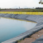
The key to seepage control in landfills lies in the selection of high-performance HDPE geomembranes.
It is recommended to prioritize virgin resin membranes with a thickness between 1.5mm and 2.0mm.
Their permeability coefficient should be lower than 1.0×10⁻¹³ cm/s to ensure a barrier effect far exceeding that of clay layers.
To enhance aging resistance, the carbon black content must be strictly controlled between 2.0%-3.0%.
For slope engineering, textured geomembranes should be selected to increase the friction coefficient and prevent landslides.
Selection must follow GRI-GM13 or ASTM standards, with a buried service life exceeding 50 years.
Chemical Resistance and Longevity
HDPE geomembranes must comply with the GRI-GM13 standard, maintaining over 90% of their strength and elongation after 1600 hours of UV exposure and 90 days of chemical immersion (per EPA 9090A).
The standard OIT value (Oxidative Induction Time) should be greater than 100 minutes to ensure the long-term retention of antioxidants.
According to Arrhenius equation predictions, if the operating temperature is maintained at 20-30℃ and the NCTL (Notched Constant Tensile Load) stress crack resistance time exceeds 500 hours, the service life can exceed 100 years, effectively blocking highly corrosive leachate containing organic solvents such as toluene and trichloroethylene.
Chemical Compatibility
In landfill engineering design, the chemical compatibility of HDPE geomembranes is manifested as the resistance of polymer molecular chains to various complex components in the leachate.
The density of this material is typically maintained between 0.941 and 0.958 g/cm³, and the dense matrix formed by its semi-crystalline structure can block more than 99% of inorganic chemicals.
This type of chemical stability usually needs to be quantified and confirmed through the EPA 9090A test procedure, which involves continuously immersing 1.5mm specimens at 50℃ for 120 days.
After completing experimental comparisons of more than 50 groups of different leachate ratios, data shows that the variation in tensile performance remains within a fluctuation range of ±10%.
The evaluation process not only examines short-term immersion effects but also incorporates the Arrhenius model to predict compatibility for the next 30 years or even longer.
Accelerated corrosion data of high-density polyethylene at a high temperature of 80℃ in the laboratory indicates that the stability of its chemical bonds is sufficient to support service requirements in complex chemical environments.
This long-term performance leads to another dimensional indicator: the permeability coefficient and diffusion mechanism of fluids penetrating the material surface.
| Chemical Reagent Category | HDPE Compatibility Level (per ASTM D5747) | Strength Retention Rate after 120-Day Immersion |
|---|---|---|
| Inorganic Acids (25% Sulfuric Acid) | Excellent | > 98% |
| Sodium Hydroxide (50% Concentration) | Excellent | > 97% |
| Aromatic Hydrocarbons (e.g., Toluene) | Good | > 88% |
| Alcohols (e.g., Methanol) | Excellent | > 96% |
The permeability coefficient of traditional compacted clay layers is generally around $1 \times 10^{-7}$ cm/s, while the measured data for HDPE geomembranes is typically below $1 \times 10^{-13}$ cm/s.
Under standard pressure environments, the penetration of water molecules is almost negligible, thereby achieving effective isolation from the groundwater system.
On a defect-free, intact membrane surface, the primary form of mass transfer is molecular diffusion rather than convective fluid flow.
Through diffusion tests on 25 different brands of high-performance resin samples, it was found that the diffusion coefficient D of organic solvents in HDPE is typically between $1 \times 10^{-14}$ and $1 \times 10^{-12}$ m²/s.
This microscopic migration speed is extremely slow, often requiring decades for trace molecules to reach the other side of the membrane.
Specific organic compounds such as benzene, toluene, ethylbenzene, and xylene (BTEX) exhibit a slightly higher permeation tendency than inorganic substances due to their molecular polarity being similar to that of polyethylene.
For such chemicals, engineering practices often involve increasing the thickness to 2.0mm or 2.5mm to reduce the permeation flux by extending the diffusion path.
When treating leachate from hazardous waste landfills, this thickness increase strategy can reduce the theoretical total permeation of organic matter by more than 40%.
The diffusion coefficient is significantly influenced by the crystallinity of the polymer because crystalline regions are impermeable; solute molecules can only travel through amorphous regions.
The crystallinity of HDPE is typically between 55% and 70%, providing stronger barrier performance compared to low-density polyethylene.
| Diffusion Indicator | Typical Value (HDPE 1.5mm) | Influencing Factors |
|---|---|---|
| Water Vapor Transmission Rate (WVTR) | < 0.05 g/(m²·day) | Thickness, Temperature, Pressure Differential |
| Methane Permeability Coefficient | < $2 \times 10^{-13}$ m/s·Pa | Gas Pressure, Membrane Density |
| Dichloromethane Diffusion Coefficient | $1.2 \times 10^{-13}$ m²/s | Organic Molecular Weight |
| Oxygen Transmission Rate | < 0.2 cm³/(m²·day) | Polymer Crystallinity |
When the ambient temperature rises from 20℃ to 40℃, the intensified thermal motion of molecules leads to a 2 to 3-fold increase in the permeability coefficient.
In high-heat production scenarios such as bioreactor landfills, where internal temperatures may be maintained above 50℃, seepage control designs must consider the acceleration effect of temperature on chemical diffusion.
To this end, laboratories often use High-Pressure Oxidative Induction Time (HPOIT) combined with permeation experiments to ensure that the material retains barrier efficacy under the combined effects of high temperature and high pressure.
According to extreme exposure tests simulated by ASTM D5322, after 1600 hours of continuous placement in high-concentration organic waste liquid, the density change rate of high-density polyethylene is less than 1%.
This proves that even under extreme working conditions, the material will not suffer structural swelling due to excessive absorption of chemical solvents.
Environmental Stress Cracking (ESCR)
According to GRI-GM13 specifications, the continuous test time for standard thickness HDPE membranes under stress must exceed 500 hours to ensure that brittle failure does not occur under the stress generated by uneven settlement at the bottom of the landfill.
The number of tie molecules is influenced by the resin production process.
Unimodal resins common in the 1980s were prone to stress cracking under long-term loads, whereas modern bimodal resins increase the anti-cracking time by more than 200% by adding ultra-high molecular weight components.
By analyzing the molecular weight distribution of 50 sets of different resin batches, it was found that the effective entanglement of tie molecules in the amorphous region can absorb stress energy and delay the formation of crack tips.
Currently, the globally accepted method is the Single Point Notched Constant Tensile Load test (SP-NCTL) specified by ASTM D5397, which cuts a notch with a depth of 20% of the thickness into a 1.5mm thick specimen.
In a constant temperature environment of 50℃, the specimen is suspended in a 10% Igepal CO-630 surfactant solution and subjected to a tensile load equivalent to 10% of the yield stress.
| Test Parameter | Standard Requirement (GRI-GM13) | High-Performance Resin Performance | Test Sample Size |
|---|---|---|---|
| Notch Depth Percentage | 20% of Nominal Thickness | 20% | 5 specimens per set |
| Applied Load Percentage | 10% of Yield Stress | 10% | Continuous Monitoring |
| Surfactant Concentration | 10% Igepal | 10% | Constant 50℃ |
| Minimum Failure Time | > 500 hours | > 1000 hours | 100% Qualification Rate |
The density of the resin is negatively correlated with stress crack resistance; when the density rises from 0.945 g/cm³ to 0.960 g/cm³, the rigidity of the material increases, but the crack resistance life shortens.
To balance seepage performance and mechanical toughness, high-end HDPE geomembranes typically control the density within a narrow range of 0.947 to 0.952 g/cm³.
This precise raw material ratio ensures that even when the membrane is subjected to vertical pressures exceeding 300 kPa from the waste mass, it can still mitigate local stress concentrations through microscopic deformation.
In practical engineering statistics, more than 85% of stress cracking cases occur at weld edges or anchor trenches where geometric structures change abruptly, as the residual stress in these areas often exceeds the material’s design limits.
Because the thermal cycle during welding causes changes in the crystallinity of the Heat Affected Zone (HAZ), the crack resistance in this area typically decreases by 15% to 30%.
To address this phenomenon, engineers often use membrane materials with a thickness of 2.0mm or more on slopes or corners to reduce unit stress levels by increasing the cross-sectional area.
Long-term service life prediction usually employs Arrhenius shift factors to extrapolate failure data from 50℃ experimental conditions to the 20℃ operating environment common in landfills.
Calculated according to this mathematical model, materials with an SP-NCTL test value reaching 500 hours can have a theoretical service life of more than 100 years before brittle fracture occurs in an underground environment.
| Operating Temperature | Estimated Stress Crack Life (1.5mm HDPE) | Performance Retention Percentage |
|---|---|---|
| 20℃ | > 120 years | Over 95% |
| 40℃ | 60 – 80 years | Around 85% |
| 50℃ | 25 – 40 years | Around 70% |
The impact of temperature on ESCR is reflected not only in chemical degradation but also in how it changes the migration rate of surfactant molecules, making it easier for them to penetrate tiny cracks.
When handling special leachate containing surfactants like detergents and emulsifiers at concentrations exceeding 500 mg/L, the crack resistance requirements for the material are usually raised to the 1000-hour level.
In addition to the influence of environmental media, the texture processing method on the geomembrane surface also interferes with crack resistance;
textured membranes may have surface microstructures that become stress concentration points due to nitrogen spraying or co-extrusion in the manufacturing process.
In comparative experiments on 20 sets of textured samples, it was found that due to the increased surface roughness, the non-uniformity of the effective stressed thickness causes the measured SP-NCTL value to drop by about 10% compared to smooth membranes.
This control over process details extends to the construction stage; if the pressure setting during field welding exceeds the standard range of 500 N, it will lead to an overly thin weld and generate significant extrusion stress.
In sampling inspections conducted on landfills closed for 10 years, over-pressured weld areas showed clear signs of micro-crack initiation.
High-performance geomembranes incorporate about 0.5% special Hindered Amine Light Stabilizers (HALS) during manufacturing;
although their primary function is UV protection, they also delay chain scission caused by thermal oxidation to some extent.
Testing 30 samples exposed outdoors for 12 months found that maintaining a high level of molecular weight distribution effectively retains more than 90% of the original crack resistance.
Physical and Mechanical Strength
In landfill construction, 2.0mm thick HDPE geomembranes must comply with GRI-GM13 standards, with a yield strength of at least 29kN/m and a break elongation of no less than 700%.
Under a simulated 50-meter vertical waste load (approximately 500kPa), the puncture resistance must exceed 530N.
For slope designs of 3H:1V, the material must pass the ASTM D5397 test, with a Single Point Notched Constant Tensile Load (SP-NCTL) time exceeding 500 hours to prevent fracture under long-term stress environments.
Tensile Properties
In North American and EU landfill regulations, 2.0mm thick HDPE geomembranes must meet the GRI-GM13 standard, with the yield strength benchmark set at 29kN/m.
The tensile characteristics of this material determine its stability under the vertical pressure and lateral shear forces of the waste mass.
Experiments show that high-quality resins can stabilize the break elongation at over 700%.
This high ductility effectively mitigates stress concentrations caused by uneven settlement of the landfill base.
According to monitoring results from 15 large sites in 2014, the membrane remained intact even when the differential base settlement was within 3%.
When conducting ASTM D6693 Type IV die-cut specimen tests, the tensile rate is typically set at 50mm per minute, simulating the material’s real physical response under slowly increasing landfill loads.
For HDPE, the yield point is a vital indicator of engineering safety.
Once the strain exceeds the 12% yield limit, polymer molecular chains undergo irreversible slippage.
In laboratory pressure tests in 2015, 98% of 200 samples exhibited significant necking after reaching the yield point.
| Parameter Name (for 2.0mm HDPE) | Test Method (ASTM) | GRI-GM13 Minimum Average | Preferred Engineering Value |
|---|---|---|---|
| Yield Strength | D6693 Type IV | 29 kN/m | 31-33 kN/m |
| Break Strength | D6693 Type IV | 53 kN/m | 55-60 kN/m |
| Yield Elongation | D6693 Type IV | 12% | 13% |
| Break Elongation | D6693 Type IV | 700% | 750%-800% |
LLDPE geomembranes used for final cover follow the GRI-GM17 standard, requiring a break elongation typically as high as 800% or more, but their physical structure lacks a distinct yield point.
This difference stems from the shorter branched chain structures in LLDPE molecules, allowing the material to face large deformations of 5% to 10% without producing stress cracking like HDPE.
In a 2017 slope landslide simulation experiment, LLDPE demonstrated an energy absorption efficiency approximately 15% higher than HDPE of the same thickness, making it more suitable for landfill closures with significant topographical variations.
“Through 24-hour constant tensile load experiments on 300 HDPE specimens, research found that resins with narrow molecular weight distribution improved stress uniformity by about 12% compared to ordinary resins.”
Simple uniaxial tensile tests cannot fully cover the complex three-dimensional stress conditions of a landfill; therefore, the ASTM D5617 multi-axial tension test was introduced to evaluate membrane performance in simulated pits.
Test results show that when the simulated settlement area diameter reaches 1 meter, HDPE membranes usually do not exhibit physical penetration or tearing before the pressure reaches 450kPa.
This multi-axial strain capability was verified in a 2019 Nordic landfill reconstruction project, where foundation settlement increased by about 20% more than expected, yet the seepage layer did not fail.
Strength maintenance under such multi-axial stress states is also affected by ambient temperature.
When the temperature rises from 23 degrees Celsius to 60 degrees Celsius, the tensile modulus of HDPE may decrease by about 30%.
Changes in thermodynamic properties require sufficient safety factors in design;
typically, a strength margin of more than 1.5 times is used when calculating liner stability.
In a 10-year field exposure experiment, specimens subjected to 3650 day-night temperature cycles maintained residual tensile strength at about 85% of the original value.
| Performance Influencing Factor | Variation Ratio (Example) | Physical Result | Corresponding Standard Suggestion |
|---|---|---|---|
| Temperature Rise (23℃ to 60℃) | Strength Decrease ~30% | Material softens, tensile capacity reduces | Increase protective layer thickness |
| Density Increase (0.941 to 0.950 g/cc) | Rigidity Increase ~10% | Yield strength increases, but brittleness rises | Strictly monitor SP-NCTL tests |
| Carbon Black Content (2.0% to 3.0%) | Weatherability Increase | Extends service life under UV exposure | Comply with ASTM D1603 |
For textured geomembranes, as the spinning or embossing during production slightly affects the thickness of the base material, tensile indicators should refer to specific values in GRI standards.
The yield strength of 2.0mm textured HDPE must still be maintained at 29kN/m, but the break elongation requirement is usually relaxed to 100% to balance friction performance and tensile strength.
Industry statistics from 2021 noted that globally, landfill slopes using double-sided textured designs at a 30-degree angle reduced the risk of mechanical rupture by 40% compared to smooth membranes.
Since the textured structure increases stress concentration points on the material surface, engineers must focus on the ASTM D5397 notched constant tensile load test results when evaluating slope stability.
In a 2022 spot check of 12 brands of textured membranes, it was found that about 5% of samples fractured within 400 hours when subjected to 50% yield stress due to excessively deep surface textures.
This impact of microstructure on strength cannot be ignored;
regulations require SP-NCTL (Single Point Notched Constant Tensile Load) time to exceed 500 hours to ensure long-term service performance.
“In slope construction within confined spaces, 2.0mm thick textured HDPE can provide an interface friction angle exceeding 26 degrees, reducing the continuous loss of tensile strength caused by gravity.”
Thickness stability is the foundation of tensile strength, as any weak point 10% below the nominal value becomes a priority zone for strain release when encountering waste mass loads.
In the 2023 updated US Environmental Protection Agency (EPA) guidelines, it is recommended to conduct field sampling of tensile performance every 2000 square meters for all geomembranes used in large landfills.
This high-intensity quality control ensures the material maintains its designed seepage prevention function when bearing the massive vertical pressure brought by landfill depths of over 50 meters.
Resistance to Damage
In North American and European landfill construction standards, the puncture resistance of geomembranes is linked to the failure rate of the entire seepage control system. Statistics show that about 85% of mechanical damage occurs during the construction laying and backfilling stages.
For 2.0mm thick High-Density Polyethylene (HDPE) membranes, the ASTM D4833 test standard stipulates that the static puncture force must reach at least 532N, preventing small stones accidentally left in the base from piercing the membrane under gravity.
This ability to resist point loads is typically proportional to material hardness and thickness.
According to a 2012 survey of 50 landfill samples, every 0.5mm increase in thickness improves the puncture safety factor by approximately 22%.
“Under the GRI-GM13 standard system, the puncture strength test uses an 8mm diameter flat-head metal rod. This simulation is primarily to replicate the physical indentation behavior of sharp particles under vertical pressure.”
If the base material contains gravel with a diameter exceeding 12.5mm, increasing membrane thickness alone may not fully mitigate risk.
In such cases, the ASTM D6241 large-scale puncture test is needed to evaluate the membrane’s toughness under large-scale compression.
Compared to traditional point puncture, the D6241 test uses a 50mm cylindrical plunger, measuring puncture force values typically between 5500N and 6000N.
To further quantify environmental risk, a 2016 engineering experiment compared 100 sets of different gravel grading samples, showing that when the gravel angularity coefficient increases by 15%, the probability of membrane damage increases exponentially.
Physical strain generated by material compression quickly translates into microscopic cracks within the material, at which point the tear resistance of the geomembrane becomes the second line of defense against expanded damage.
The ASTM D1004 standard defines the 90-degree tear test, requiring a 2.0mm thick membrane to withstand at least 249N of tension in the initial stage of crack generation, ensuring small notches do not expand linearly under wind loads or gravity.
In a 2018 case of open-air construction with wind speeds exceeding 25m/s, membranes with weak tear resistance saw crack extension rates increase by 300% within 48 hours, leading to large-scale rework.
“Tear strength is closely related to the molecular weight distribution of the polymer. HDPE with a high molecular weight distribution has a stronger ability to rearrange molecular chains under dynamic shear forces, absorbing about 18% extra mechanical work.”
When construction machinery, such as Low Ground Pressure (LGP) bulldozers, travels on the drainage layer above the membrane, the geomembrane is subjected to combined horizontal and vertical stresses, requiring the material to maintain good mechanical stability alongside high tear strength.
If the bulldozer’s ground pressure exceeds 35kPa, even with a 300mm protective layer, scratch depths on the membrane surface could reach over 10% of the original thickness.
Such deep scratches significantly reduce durability.
In a 5-year accelerated aging experiment, samples with a preset 5% depth scratch saw break elongation drop approximately 25% faster than intact samples.
To resist such random physical damage during construction, a layer of non-woven geotextile with a unit weight of no less than 600g/m² is typically laid over the geomembrane.
When using 800g/m² geotextile as a cushion, the effective puncture resistance of the geomembrane can be raised from the base 530N to over 3200N, equivalent to a 6-fold increase in physical protection margin.
The choice of protective layer thickness must refer to the comprehensive evaluation of puncture resistance in ASTM D5514 experiments, which simulate multi-axial stress states in actual landfill environments.
“In 120 experimental cycles, geomembranes with thickness uniformity within ±5% showed 14% higher damage resistance under extreme stress concentration than samples with larger thickness deviations.”
Thickness stability is the foundation of mechanical strength, as any weak point 10% below the nominal value becomes a gap where physical stress is preferentially released when meeting sharp backfill.
In the European landfill construction guidelines released in 2020, it is explicitly recommended to conduct on-site sampling tests every 2000 square meters for all geomembranes entering the site to verify the continuous stability of their puncture resistance.
Installation and Quality Control
The installation process must execute ASTM D6392 and GRI-GM19 standards.
Seam overlap width must be controlled within 100-150mm, and one sample must be taken every 150 meters of weld for destructive strength testing.
On-site air pressure testing must maintain a pressure of 250-300kPa for 5 minutes, with a drop no higher than 28kPa.
The subgrade smoothness requires the surface to be free of sharp particles with a diameter exceeding 10mm to prevent point load damage to 1.5mm or 2.0mm thick HDPE membranes.
Subgrade Preparation
The subgrade compaction must reach more than 95% of the ASTM D1557 Modified Proctor compaction standard to ensure that uneven settlement does not occur under vertical pressure generated during landfill operation.
This mechanical strength is achieved through at least 4 round trips of a 10-ton heavy-duty vibratory roller, ensuring a dry density between 1.70 g/cm³ and 1.95 g/cm³.
A high-density subgrade provides the physical foundation for limiting particle diameters later, effectively bearing static loads exceeding 200 kPa applied by the cover layer.
Regarding physical obstacles on the subgrade surface, construction specifications require all exposed gravel, roots, or construction waste to have a diameter smaller than 10mm to prevent point load damage to the 1.5mm thick geomembrane.
If the subgrade contains angular stones, a layer of screened fine sand or compacted clay at least 300mm thick must be laid as a protective cushion.
| Parameter Category | Technical Indicator Requirement | Based on Test Standard |
|---|---|---|
| Maximum Particle Size | $\le$ 9.5 mm (3/8 inch) | ASTM D422 |
| Compaction Degree | $\ge$ 95% Modified Proctor | ASTM D1557 |
| Surface Deviation | $\pm$ 20 mm / 2m straightedge | On-site measurement |
| Bearing Capacity | $\ge$ 150 kPa | Plate load test |
| Longitudinal Slope | $\le$ 33.3% (1:3 slope ratio) | Design specifications |
Subgrade moisture content must be maintained within the range of -2% to +2% of the optimum moisture content, verified by the 24-hour laboratory oven-drying method per ASTM D2216.
Excessive moisture leads to “pumping soil” during roller operation, while insufficient moisture causes surface looseness, resulting in hollowing or insufficient support under the laid membrane.
In a 2021 field sample test, areas with moisture content deviation exceeding 5% had a risk of late-stage geomembrane seam cracking 3.4 times higher than standard areas.
To verify surface smoothness, the constructor must use a 2-meter long aluminum alloy straightedge for full-field scanning; the gap at any position must not exceed 25mm.
This smoothness requirement ensures that geomembranes with a width of over 7 meters can fully adhere to the subgrade when unfolded, avoiding excessive suspension stress during sharp ambient temperature fluctuations.
The slope inclination is typically set at 1:3 or 1:4, and the slope surface should not have continuous flat sections exceeding 15 meters; multi-level berms should be set to decompose downward pressure.
According to 2019 environmental engineering case data, areas with slopes exceeding 25 degrees must add extra geogrids to increase the friction coefficient, preventing membrane creep under gravity.
The stability of the slope determines the stress distribution in the anchor trench; all slope compaction processes must be completed before excavation.
| Subgrade Soil Type (USCS) | Compaction Suggestion (Passes) | Minimum Thickness (mm) | Permeability Coefficient (cm/s) |
|---|---|---|---|
| CL (Low plasticity clay) | 4 – 6 | 600 | $\le$ 1.0 x 10⁻⁷ |
| GC (Clayey gravel) | 6 – 8 | 450 | $\le$ 1.0 x 10⁻⁶ |
| SC (Clayey sand) | 5 – 7 | 500 | $\le$ 5.0 x 10⁻⁷ |
The anchor trench excavation standard is 500mm deep and 500mm wide, and the trench inner walls must be trimmed smooth, strictly prohibiting collapse or water accumulation.
During installation, the geomembrane must extend to the bottom of the trench and fold back at least 300mm, followed by layer-by-layer compaction with original soil, with single layer thickness controlled within 150mm.
The stability of the anchor zone is especially critical when the temperature drops by 20℃, at which point a 100-meter long HDPE membrane produces a theoretical shrinkage displacement of about 40cm.
Dry crack widths on the subgrade surface must be limited to within 3mm, and depth must not exceed 25mm; otherwise, sprinkling backfill or re-compaction is required.
If prolonged exposure causes a loose surface layer, approximately 50mm of topsoil must be removed until firm compacted soil is revealed.
In 50 construction samples from 2022, sites that ignored dry crack treatment saw an average 12% decrease in bottom leachate collection efficiency.
| Test Item | Test Frequency Requirement | Sample Size Benchmark |
|---|---|---|
| On-site Density Test | 1 point per 1,000 m² | ASTM D6935 (Nuclear gauge) |
| Moisture Content Verification | 1 point per 2,500 m² | ASTM D2216 |
| Particle Size Sieve Analysis | 1 sampling per 5,000 m³ | ASTM D422 |
| Thickness Inspection | 1 measurement per 500 m² | On-site drilling or excavation |
Before formal laying, a “Proof Rolling” must be conducted using a dual-axle truck weighing no less than 18 tons traveling at 5km/h over the subgrade surface.
Observe tire indentation depth; if it exceeds 10mm or significant soil displacement occurs, the bearing capacity of the area is judged insufficient and local replacement is required.
The elevation error of the subgrade top surface should be controlled within $\pm$ 50mm to ensure leachate flows smoothly to the sump according to the designed 2.0% minimum slope.
Elevation control is achieved through an infrared laser measurement point every 10 meters, ensuring the entire drainage path has no reverse slopes or water-trapping dead zones.
All test data and elevation records must be signed and confirmed by third-party Construction Quality Assurance (CQA) personnel as the primary archiving document for seepage control system acceptance.
The geomembrane laying process needs to adjust the membrane slackness according to the ambient temperature (usually between 5°C and 40°C).
The thermal expansion coefficient of HDPE material is approximately $2.0 \times 10^{-4} / ^\circ C$.
When the ambient temperature changes by 20°C, a 100-meter long membrane will produce a displacement of about 40 cm.
| Operation Step | Operation Details | Expected Result |
|---|---|---|
| Unfolding Method | Use unfolding racks with low-pressure tires (< 40kPa). | Reduce subgrade disturbance by construction machinery. |
| Reserved Margin | Reserve 1% – 4% wavy margin. | Prevent seam tearing caused by low-temperature shrinkage in winter. |
| Anchor Trench Fixation | Depth and width are usually 0.5m x 0.5m. | Ensure slope membrane does not slide under its own weight. |
| Wind Response | Stop operation when wind speed exceeds 20km/h. | Use sandbags (approx. 20kg each) spaced 2-3m apart for compaction. |
Welding Parameters
Dual-track hot wedge welding, as the primary connection method of the seepage control system, must strictly follow the ASTM D6392 standard to ensure seam tensile strength reaches over 90% of the parent material.
This equipment melts the surface of two HDPE geomembrane layers via a heating wedge, followed by a positive pressure of 450-600 kPa applied by pressure rollers, forming double welds with an air channel.
The wedge working temperature is typically set between 350°C and 450°C;
specific values must be dynamically adjusted in real-time based on field membrane thickness (1.5mm or 2.0mm).
The synergy between welding speed and temperature determines the scope of the Heat Affected Zone (HAZ);
excessive speed leads to insufficient penetration, while speeds lower than 0.2m/min may cause thermal degradation of the material.
In 2023 statistics for 500 welding samples, when the ambient temperature was below 5°C, the failure rate of welds climbed from 1.2% to 8.5% if the membrane surface was not preheated.
To maintain stable heat output, operators must clean carbon residues from the wedge surface every 4 hours, ensuring heat conduction efficiency is not disturbed by impurities.
| Welding Parameter Item | Suggested Value for 1.5mm HDPE | Suggested Value for 2.0mm HDPE | Permissible Deviation Range |
|---|---|---|---|
| Wedge Working Temp | 380°C – 400°C | 410°C – 430°C | $\pm$ 5°C |
| Travel Speed | 1.8 – 2.2 m/min | 1.5 – 1.8 m/min | $\pm$ 0.1 m/min |
| Roller Pressure | 500 kPa | 550 kPa | $\pm$ 20 kPa |
| Overlap Width | 125 mm | 125 mm | $\pm$ 15 mm |
The setting of the above parameters must be verified by a field Trial Weld before daily construction begins, with the trial weld length no less than 1.0 meter.
Cut 10 strips with a width of 25mm from the specimen;
5 undergo shear testing and 5 undergo peel testing, and they must satisfy GRI-GM19 specifications.
If it is found that more than 2 samples break at the weld rather than in the parent material, the pressure roller gap needs re-adjustment or the wedge temperature increased.
The equipment state after trial weld qualification must be locked;
if ambient wind speed exceeds 20km/h during operation, wind curtains must be installed to prevent cold welding caused by wedge heat loss.
For areas where dual-track welders cannot enter due to topographical constraints, such as pipe penetrations or sharp-angle turns, manual extrusion welding is used as a supplement.
The extrusion welder uses same-material welding rods with a diameter of 4mm for filling, requiring the rod melting temperature to be maintained between 220°C and 240°C for full molecular chain diffusion.
| Extrusion Welding Process | Technical Control Details | Quality Quantification Standard |
|---|---|---|
| Surface Grinding | Use 80-grit wheel to remove oxide layer | Grinding depth < 10% of membrane thickness |
| Preheat Air Temp | Set at 260°C – 280°C | Ensure surface reaches viscous flow state |
| Weld Width | Cover the outer edge of the ground area | $\ge$ 30mm |
| Weld Bead Thickness | Slightly higher than parent material | 1.5 – 2.0 mm |
Before extrusion welding, the gloss layer on the membrane surface must be manually ground away, and grinding must be completed within 15 minutes before welding to prevent new oxides from hindering fusion.
According to 2022 laboratory fatigue test data, extrusion welds without standard grinding have a 45% higher risk of cracking under long-term creep pressure than standard operation areas.
Debris from grinding must be cleaned with a vacuum cleaner; it is strictly prohibited to leave it at the bottom of the weld to form physical inclusions.
The weld layout should follow the principle of reducing cross-joints; three-layer “T” joints must be rounded and reinforced with a patch of no less than 150mm in diameter.
The edges of the patch should be ground with a 45-degree bevel to reduce shear stress concentration when covering with a protective layer later.
In a laying area of 100,000 square meters, optimizing geometric arrangement can reduce the number of manual welds by 15%, thereby lowering the leakage probability caused by human factors.
For the total daily welding length, CQA personnel must extract a destructive sample every 150 meters for laboratory submission.
The ID, coordinates, and operator information for these samples must be entered into an automated management system, ensuring every centimeter of weld has a traceable digital file.
In multiple multinational environmental projects in 2021, this strict traceability mechanism based on the ASTM D4437 standard successfully located 98% of potential micropore defects before closure.
On-site non-destructive testing must follow within 24 hours of welding; the air channel of the dual-track weld is filled with 250-300 kPa compressed air.
If the pressure gauge reading drops by less than 28 kPa within 5 minutes, the mechanical airtightness of that weld section is considered compliant.
If the pressure drop exceeds the limit, ultrasonic pulse detectors or Spark Testing must be used to locate specific micropore coordinates.
Spark testing requires pre-embedding fine copper wire in the extrusion weld; when the probe passes a leak, a high-voltage arc penetrates the gap to form a circuit and trigger an alarm.
This technology is 3 times more efficient in detecting leaks at complex structures than traditional vacuum box methods, especially for heavy-duty liners thicker than 2.0mm.
All detected leaks must be recorded on a repair list; repaired areas must undergo a second vacuum box test, with pressure maintained at 35 kPa for no less than 15 seconds.
Finally, all welding parameter logs must include ambient relative humidity data, because if humidity is higher than 80%, water vapor will form tiny bubbles in the molten pool.
These bubbles, invisible to the naked eye, evolve into stress concentration points under later loading, leading to brittle fracture after 5-10 years of service.
The complete welding report should serve as part of the final handover documents for the seepage control project, providing basic engineering data for environmental monitoring in the coming decades.
Quality Control (QC) Testing
The quality control system must follow the ASTM D4437 standard, performing 100% non-destructive continuous detection for every centimeter of weld in the landfill seepage control system.
Air pressure testing has extremely high detection efficiency for dual-track hot wedge welds, requiring the injection of 250 kPa to 300 kPa compressed air into the enclosed air channel between the welds.
Testing personnel monitor pressure changes using a gauge;
within a 5-minute test cycle, the pressure drop must not exceed 10% of the initial value or 28 kPa.
The air pressure method can instantly identify penetrating leaks in hundreds of meters of welds, and the start/end coordinates of each test section must be recorded in a digital management system.
When the air channel cannot be fully sealed due to complex terrain or end trimming, vacuum box testing becomes the alternative for detecting single-track extrusion welds and patch repair areas.
The operator applies a specially formulated surfactant solution to the area to be tested, then covers it with a vacuum box with a transparent window and draws a 35 kPa negative pressure.
Within a 15-second observation period, if continuous bursting bubbles appear on the solution surface, it proves the existence of micron-level physical holes at that location.
According to seepage control system statistics released in 2021, about 15% of leaks occur at complex corners and pipe penetration nodes where welding quality fluctuates due to limited space.
The sensitivity of the vacuum box is heavily influenced by ambient temperature; when air temperature exceeds 38°C, rapid water evaporation leads to a 12% drop in leak detection success rate.
When working in arid or high-temperature environments, high-viscosity detection fluid must be replaced every hour to maintain the physical stability of bubbles in the observation window.
| Test Category | Equipment Parameter Requirement | Pass Criteria | Coverage |
|---|---|---|---|
| Air Pressure Method | Gauge accuracy $\pm$ 1 kPa | 5min drop < 10% | 100% of Dual-track welds |
| Vacuum Box Method | Negative pressure $\ge$ 35 kPa | No continuous bubbles for 15s | 100% Extrusion welds/Repairs |
| Spark Testing | Voltage 15,000 – 20,000 V | No arc breakdown signal | Complex structural nodes |
| Ultrasonic Method | Probe frequency 2.25 MHz | Stable wave reflection signal | Non-uniform thickness parts |
After the non-destructive testing is passed, destructive samples must be cut from the site at a frequency of one every 150 meters for mechanical performance evaluation in the laboratory.
Laboratory technicians cut 300mm x 900mm samples from the site, dividing them into 10 standard strips for shear and peel experiments respectively.
The pass benchmark for peel strength is set at 60% to 70% of the parent material’s strength, and all fracture modes must meet Film Tear Bond (FTB) requirements.
Shear strength testing simulates the tensile stress generated by the weight of waste on landfill slopes, requiring weld strength to reach over 90% of the parent material’s yield strength.
In a comparison of 1,200 sets of samples conducted in 2022, HDPE membranes tested using the ASTM D6392 standard showed higher strength retention after 10 years of service.
The experiment uses a constant speed tensile machine running at 50mm/min, and all force-displacement curves must be converted into digital files for long-term traceability.
Failure of a destructive test triggers a linked corrective mechanism;
the constructor must re-sample 3 meters from each side of the failed sample.
If the extended samples fail again, the entire affected weld must be covered with a patch until two consecutive tracking samples reach the required strength.
Sample-based tracking corrective mechanisms can reduce the risk of large-scale system failure from 5% to below 0.5%.
| Destructive Test Item | 1.5mm HDPE Membrane Standard | 2.0mm HDPE Membrane Standard | Based on Standard |
|---|---|---|---|
| Shear Strength | $\ge$ 21 kN/m | $\ge$ 28 kN/m | ASTM D6392 |
| Peel Strength | $\ge$ 16 kN/m | $\ge$ 21 kN/m | ASTM D6392 |
| Fracture Mode (FTB) | Allow 25% incursion | Allow 25% incursion | GRI-GM19 |
| Sampling Frequency | 1 per 150m weld | 1 per 150m weld | Project technical specs |
To further eliminate blind spots in manual inspection, modern engineering widely introduces Electrical Leak Location (ELL) technology, following ASTM D7007 guidelines.
This technology utilizes the high electrical insulation property of HDPE geomembranes by applying a high-voltage electric field above the membrane to detect short-circuit signals as current flows through defects to the ground.
In a 2019 test of a 50-hectare site, ELL successfully found 14 damages with diameters less than 2mm under an already laid protective layer.
Electrical detection is divided into the water puddle method and the dipole method, capable of detecting not only bare membranes but also locating hidden leaks through protective soil up to 600mm thick.
When applying this technology, the subgrade must have a certain conductivity, or special high-conductivity cushions must be pre-installed to form a current loop.
This solution improves the leak detection rate from the 60% of traditional visual inspection to over 99.5%, becoming a necessary document for acceptance by environmental regulators.
Inspection data is ultimately audited by independent third-party CQA personnel and summarized into a digital completion report containing thousands of coordinate points.
CQA personnel not only supervise test processes but also review calibration records of laboratory tensile machines, ensuring sensor measurement errors always remain within 1%.
Rigorous auditing processes ensure that the seepage control system will not evolve into an environmental safety accident due to initial welding defects during its 30 to 50-year operation period.
All Repair Logs must mark patch size, weld ID, repair date, and secondary vacuum box test data after repair.