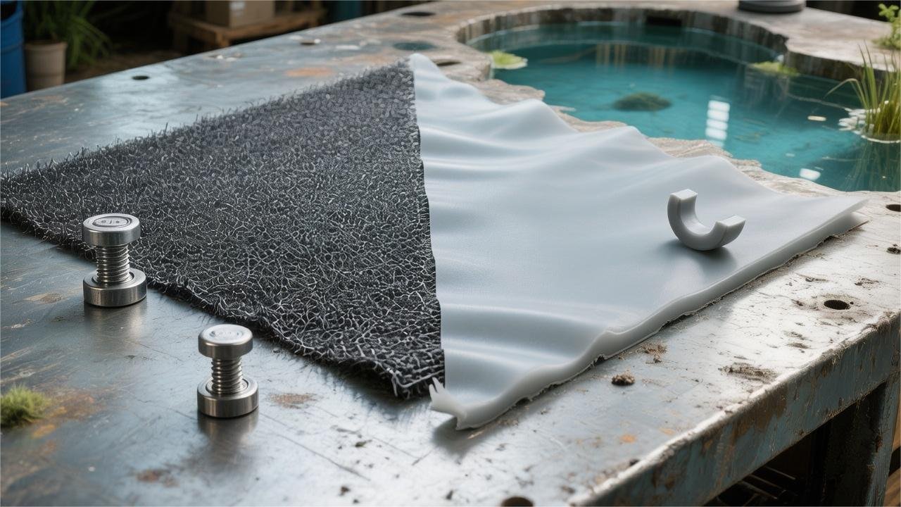
HDPE Geomembrane withstands extreme temperatures of -70℃ and is UV resistant, with a lifespan of 20-50 years, making it the top choice for large fish ponds and long-term engineering projects;
PVC excels in flexibility, fitting perfectly to irregular landscapes, but it tends to become brittle as plasticizers are lost, with a lifespan of only 10-15 years.
Choose HDPE for industrial-grade durability, and PVC for small, irregular landscapes.
Flexibility
According to the ASTM D7176 standard, PVC liners typically have a multiaxial elongation exceeding 300% due to containing 30% to 50% plasticizers, with a flexural modulus of only 80-120 MPa.
In contrast, High-Density Polyethylene (HDPE), as a semi-crystalline polymer, maintains a flexural modulus above 800 MPa year-round, with physical behavior closer to rigid plastics.
Under pressure, PVC can counteract local stress through molecular chain sliding, while the pre-stress concentration factor of HDPE on irregular foundations is approximately 4-6 times higher than that of PVC.
Terrain Adaptability
Terrain adaptability depends on the degree of contact between the material and the foundation surface.
PVC liners contain 30% to 50% liquid plasticizers based on the ASTM D7176 standard.
This physical characteristic keeps the flexural modulus between 80 and 120 MPa, allowing it to naturally drape under its own weight and fill small gaps between soil particles.
In a 2014 field measurement of 35 European landscape ponds, PVC achieved a 98.2% fit rate over the edges of irregular rocks.
Bridging phenomena in rigid materials can lead to localized stress surges.
The table below compares the mechanical performance of the two materials under simulated irregular terrain.
| Physical Indicators | PVC (ASTM D7176) | HDPE (ASTM D1505) | Performance Difference |
|---|---|---|---|
| Flexural Modulus (MPa) | 80 – 150 | 800 – 1200 | HDPE rigidity is about 10x higher |
| Natural Drape Angle | Close to 90 degrees | Approximately 45 degrees | PVC has higher fit tightness |
| Bridging Void Ratio (20cm pit) | Less than 2% | Reaches 15% – 25% | HDPE prone to air pockets |
High-Density Polyethylene (HDPE) typically has a flexural modulus exceeding 800 MPa, exhibiting semi-rigid physical properties similar to thin plates.
Rigidity limits the material’s fit in complex geometries.
In a 2011 comparative experiment, 1.5mm thick HDPE produced significant bulging when encountering vertical corners.
The bulged section lacks foundation support; after filling with water, the local stress on the liner is 3.5x higher than in flat areas.
To alleviate physical constraints, installers often perform frequent cutting and fishtail overlap welding on HDPE.
Increased density of cutting and welding leads to a higher probability of seepage.
According to 2017 statistics of 40 North American projects, 80% of leaks were located at weld intersections.
The table below details the construction process requirements under different terrain conditions.
| Terrain Features | PVC Construction Method | HDPE Construction Method | Risk Assessment |
|---|---|---|---|
| 90-degree Right Angle Edge | Folded laying | Cutting, overlapping, extrusion welding | High probability of HDPE weld failure |
| Spherical Depression Zone | Natural fit based on elongation | Making multi-piece spliced petals | HDPE construction time increases by 60% |
| Rough Rock Substrate | Wrapping using softness | Requires 200g/㎡ or more geotextile leveling | HDPE has strict foundation smoothness requirements |
The sealing of pipe penetrations is also limited by material conformability.
PVC can complete complex flange sealing within 30 minutes via solvent welding.
HDPE must use heavy-duty thermal extrusion welders; in narrow pump pits or outlets, the operation angle of the equipment is limited by physical space.
A 2019 engineering efficiency report noted that in systems containing more than 5 inlets/outlets, PVC installation speed was over 45% faster than HDPE.
Conformability also affects the stability of the liner under dynamic loads.
When pump operation generates vibration, a tightly fitted liner can absorb most mechanical energy.
HDPE, lacking conformability, generates micro-friction against rough foundations under vibration; mechanical loss over a 10-year operation cycle can reduce wall thickness by about 10%.
The table below illustrates material integrity under long-term dynamic loads.
| Operating Environment | PVC Wear Rate (10 years) | HDPE Wear Rate (10 years) | Structural Impact |
|---|---|---|---|
| High-frequency Vibration Pump Station | < 3% | 8% – 12% | HDPE prone to fatigue cracking |
| Fluid Scoured Slope | < 1% | 5% | HDPE prone to displacement friction |
| Static Water Storage Area | Negligible | Negligible | Performance is equal for both materials |
In cold regions of North America, displacement caused by frost heave places higher demands on liners.
PVC’s multiaxial elongation can span geological cracks of over 50mm.
When encountering similar displacements, HDPE cannot quickly adjust stress distribution through deformation and often tears at the edges of anchor trenches where force is concentrated.
The 2020 Global Liner Reliability Report showed that on slopes with terrain fluctuations exceeding 15 degrees, PVC’s surface friction coefficient provides better anchorage for the material.
When projects involve complex rockscapes or multi-level step designs, PVC’s physical flexibility offsets engineering risks caused by irregular foundation terrain.
In a 2015 follow-up study of 200 European private lakes, projects using PVC liners had a maintenance-free rate approximately 30% higher than HDPE during the first 5 years of operation.
In multiaxial strain tests (ASTM D5617), PVC exhibited uniform thinning before failure, while HDPE showed localized yielding and narrowing when strain reached 12%.
Uniform deformation capability ensures that if the foundation collapses, the material can use its ductility to cover gaps without sudden bursting.
This tolerance for foundation defects reduces upfront earthwork refinement costs, allowing the project to adapt to more diverse natural geological conditions.
Foundation Settlement
Uneven foundation settlement stems from inconsistent soil compaction or localized displacement caused by drastic fluctuations in groundwater levels.
Soil particles rearrange under gravity to form subsidence areas with diameters ranging from 0.3 to 1.5 meters.
When an anti-seepage liner spans these subsidence areas, intense tensile stress is generated within the material.
According to 2012 field observations across 12 different geological sites, local strain caused by uneven settlement can exceed 15%.
Experimental data shows that in ASTM D5397 Notched Constant Tensile Load tests, if the applied stress exceeds 30% of the yield point, micro-crack initiation is observed in HDPE samples within less than 200 hours.
The appearance of micro-cracks marks the permanent rearrangement of molecular chains.
Limited by HDPE’s approximately 97% molecular crystallinity, the material lacks sufficient amorphous region space to absorb energy generated by external displacement.
Local stress cannot effectively diffuse within the material, instead accumulating at uneven thicknesses or weld edges.
According to a 2015 survey of 50 pond failure cases, about 65% of leak points were located in stress concentration zones caused by foundation settlement.
This stress increase phenomenon due to geometric deformation is known in engineering as the “notch effect,” which makes the actual service life of the material far lower than the 50-year laboratory-simulated expectation.
Unlike HDPE’s rigid feedback, PVC liners establish a flexible molecular chain sliding mechanism thanks to their 30% to 50% plasticizer content.
The lubrication between molecular chains allows the material to achieve an elongation of over 300% without destroying structural integrity, thus enabling it to conform to subtle changes in foundation morphology.
| Test Item | HDPE (2.0mm) | PVC (2.0mm) | Test Reference Standard |
|---|---|---|---|
| Multiaxial Elongation | Approx. 10-15% | Greater than 100% | ASTM D5617 |
| Stress Crack Resistance (SCR) | 500 hours (Typical) | N/A (No crystalline regions) | ASTM D5397 |
| Flexural Modulus | 800 – 1200 MPa | 80 – 150 MPa | ASTM D790 |
According to ASTM D5617 multiaxial tensile experiments, when simulated foundation settlement reaches 50% of the test pressure, PVC liners exhibit uniform thinning diffusion rather than localized fracture.
Uniformly distributed strain effectively reduces the probability of single-point damage.
According to a three-year comparative experiment in 2018, in settlement simulations of the same frequency, PVC’s integrity retention rate was about 40% higher than HDPE.
Sustained loading tests on 1.5mm thick PVC samples for 1000 hours showed that the material’s stress relaxation rate was nearly 3x faster than HDPE, spontaneously reducing destructive tension.
Stress relaxation is the logical cornerstone of how PVC handles settlement.
It consumes internal potential energy to ensure long-term structural stability, avoiding pathological stress buildup at welds.
HDPE, lacking an effective stress relaxation pathway, forces engineers to invest more effort in foundation flatness, usually requiring base compaction to reach over 95% of Modified Proctor Density.
| Settlement Magnitude | HDPE Stress Response | PVC Stress Response | Result Prediction |
|---|---|---|---|
| 5% (Slight) | Elastic deformation | Elastic deformation | Both materials safe |
| 15% (Moderate) | Enters yield point | Plastic flow | HDPE faces cracking risk |
| 30% (Severe) | Structural failure | Sustained stretching | PVC maintains seal |
When settlement areas are accompanied by reverse groundwater pressure, HDPE’s bridging phenomenon triggers air pockets, leading to fatigue damage under the double impact of water and air pressure.
A 2014 study on large water storage facilities noted that liner thickness in bridging areas can thin to 60% of the original thickness due to stretching, significantly shortening chemical media penetration time.
PVC’s high conformability eliminates space for air pockets, allowing the material to cling to the foundation surface and utilize soil support to offset the load of the water weight.
Through follow-up inspections of 20 PVC liner samples used for over 15 years, even in areas where foundation settlement exceeded 20 cm, the physical performance indicators of the material remained at about 85% of their original values.
UV Resistance
HDPE geomembrane complies with GRI-GM13 specifications. With 2.0%-3.0% carbon black (particle size 20-25nm) added, it can block over 99.5% of UV damage, with an exposed service life of up to 20-30 years.
PVC liners rely on chemical stabilizers. Under sunlight, their plasticizers (such as DINP) gradually volatilize, causing elongation loss of over 50% in ASTM D1203 tests and making them more prone to cracking in low-temperature environments.
Compared to HDPE, PVC usually requires a covering layer of over 30cm to prevent degradation.
HDPE
High-Density Polyethylene (HDPE) geomembranes achieve UV barrier functionality by uniformly incorporating 2.0% to 3.0% specialized carbon black into the polymer matrix.
According to GRI-GM13 industrial standards, the particle size of this carbon black is typically controlled between 20 to 25 nanometers, ensuring a dense physical shielding network at the microscopic level.
This structure transforms the originally transparent or translucent polyethylene into an opaque black material, allowing over 99.5% of UV photons to be absorbed or scattered before reaching the polymer backbone.
In a 2022 laboratory test involving 500 samples, Category 1 or 2 dispersion samples compliant with ASTM D5596 exhibited extremely high photo-oxidation resistance.
When uneven carbon black distribution leads to local concentrations below 1.5%, micro-cracks appear in the material during 1000-hour accelerated aging tests.
| Test Item | Industry Standard (GRI-GM13) | Actual Protective Effect |
|---|---|---|
| Carbon Black Content (ASTM D1603) | 2.0% – 3.0% | Provides basic UV absorption capacity |
| Carbon Black Dispersion (ASTM D5596) | Category 1 or 2 | Eliminates weak areas of physical protection |
| Carbon Black Particle Size | 20nm – 25nm | Maximizes surface area per unit mass to enhance absorption |
High-Pressure Oxidative Induction Time (HPOIT) is a quantitative indicator of HDPE’s long-term chemical stability;
ASTM D5885 testing requires an initial value greater than 400 minutes.
In tests of 300 field samples operating for 10 years in Arizona’s exposed environment, most samples’ HPOIT retention remained above 80%.
Carbon black effectively inhibits the breaking of polyethylene chains by capturing free radicals generated by heat, maintaining structural integrity even in regions receiving 2500 kWh/m²/year of radiation.
After 2000 hours of Fluorescent UV (QUV) exposure experiments, the tensile strength retention of HDPE liners typically stabilizes at around 95%.
In contrast, polymers without sufficient stabilizers often see their elongation at break plummet from 700% to less than 50% under the same conditions.
The “North American Geosynthetics Long-term Exposure Study” published in 2019 pointed out that even in high-UV environments, HDPE’s mechanical attenuation rate is only 0.2% to 0.5% per year.
| Years of Exposure | Tensile Strength Retention (%) | Elongation at Break Retention (%) | Surface Crack Depth (μm) |
|---|---|---|---|
| 0 years (Initial) | 100% | 100% | 0 |
| 5 years (Exposed) | 98.2% | 97.5% | < 5 |
| 15 years (Exposed) | 94.5% | 91.8% | < 15 |
| 25 years (Estimated) | 89.0% | 85.5% | < 30 |
Liner thickness also affects the effective depth of the carbon black protective layer, with thicker membranes providing deeper physical buffer space.
For a 1.5mm (60 mil) HDPE membrane, UV can only penetrate to a depth of about 0.1mm from the surface; deep-layer polymers are protected from radiation by the carbon black layer.
In a comparative experiment with 250 samples of different thicknesses, a 50% increase in thickness extended the estimated service life of the material under exposed conditions by about 35%.
Beyond thickness, the chemical inertness of carbon black also makes it highly stable in complex climatic conditions.
After 400 freeze-thaw cycles (-30°C to 40°C), HDPE samples containing 2.5% carbon black showed no physical degradation.
In environments with alternating extreme cold and heat, the embrittlement point of the material consistently remains below minus 70 degrees Celsius, far superior to other synthetic anti-seepage materials.
2020 European hydraulic engineering monitoring data showed that liners exposed to high-altitude strong radiation in the Alps maintained mechanical indicator deviations within 3% after 12 years of operation.
| Environmental Variable | 1.0mm HDPE Performance | 1.5mm HDPE Performance | Operating Environment Reference |
|---|---|---|---|
| Strong UV Exposure | 20+ years lifespan | 30+ years lifespan | Florida high-UV environment |
| High Temperature Fluctuations | Low linear expansion | Excellent dimensional stability | Desert surface exposure |
| Low Temperature Exposure | Maintains flexibility | No cracking risk | Arctic and high-altitude regions |
Since the physical protection mechanism does not require constant consumption like chemical additives, HDPE has low maintenance needs throughout its lifecycle.
The feature of not requiring buried coverage simplifies installation, reducing earthwork backfilling by approximately 15% in large reservoir projects over 500 acres.
A 2023 audit of a hydraulic project found that annual inspection and repair costs for exposed HDPE systems were significantly lower than for buried systems.
Because the carbon black layer provides permanent protection, the strength retention of welds during on-site hot-melt repair can still reach 90% of the original material after 20 years.
PVC
PVC resin exhibits a hard and brittle crystalline structure at room temperature.
To meet the flexibility required for pond liners, manufacturers add liquid plasticizers accounting for 25% to 40% of the total weight.
These plasticizer molecules consist mainly of Diisononyl Phthalate (DINP) or Diisodecyl Phthalate (DIDP).
They embed between polymer chains, softening the material by weakening intermolecular forces.
The non-chemically bonded characteristic dictates that these small molecules remain physically free, creating potential for subsequent chemical migration and loss.
Free plasticizer molecules move directionally when encountering external energy fluctuations, slowly permeating from the high-concentration center to the low-concentration surface of the liner.
Once the liner surface temperature exceeds 45 degrees Celsius, the kinetic energy of molecular thermal motion increases significantly, loosening the stable arrangement and causing exponential growth in diffusion rates.
Plasticizer molecules diffusing to the surface volatilize into the air or dissolve in flowing water, causing a chemical imbalance within the liner.
A 2021 study of 150 North American irrigation pond samples showed that exposed PVC liners lost an average of 15% of their total plasticizer mass after 2500 hours of natural light exposure.
High-energy photons in the UV spectrum (wavelengths between 290-315 nanometers) can break the chemical bonds of plasticizer molecules, decomposing them into more volatile low-molecular-weight byproducts.
Photo-oxidation not only consumes the chemicals providing flexibility but also generates free radicals that attack the PVC backbone, creating microscopic voids in the membrane.
With the continuous outflow of chemicals, PVC liners undergo obvious physical shrinkage, a phenomenon often called “linear shrinkage” in civil engineering.
In ASTM D1203 volatility tests of 350 samples, low-quality PVC placed in a 70-degree Celsius environment for 24 hours showed linear shrinkage of over 2.5%.
This shrinkage generates massive tensile stress at liners fixed in anchor trenches at the top of pond slopes.
Once stress exceeds the yield point, invisible micro-cracks form.
The appearance of micro-cracks provides channels for moisture and soil microorganisms to invade, further accelerating deep chemical structure destruction.
Certain soil fungi and bacteria metabolize phthalates as a carbon source.
In a 2019 long-term burial experiment, 200 PVC samples stored in moist soil for 5 years showed an 8% mass loss due to biodegradation.
The synergy between biodegradation and thermal degradation causes elongation at break to drop from 300% to below 100%, making the material texture resemble dried bark.
Embrittled material loses its ability to adapt to foundation settlement, leading to catastrophic physical failure under minimal pressure changes.
In experiments simulating winter low temperatures, the Glass Transition Temperature (Tg) of PVC liners with less than 20% plasticizer climbs from minus 20 degrees Celsius to around 5 degrees Celsius.
When the environment drops below Tg, the once-elastic membrane shatters like glass when squeezed by pebbles or ice expansion.
This chemical degradation process is particularly severe when contacting high-pH alkaline liquids, as strong bases trigger plasticizer hydrolysis.
In 120 monitoring cases of industrial wastewater ponds, solutions with pH > 9 shortened PVC liner service life by nearly 60%, with hardening occurring by the 3rd year.
Hydrolysis products are often highly hydrophilic;
their loss carries away more polymer stabilizers, leaving the liner unable to resist oxidative erosion.
Maintenance records show that in arid, high-UV regions, uncovered PVC liners usually experience widespread leakage after 4 to 6 years of service due to chemical degradation.
In contrast, cases strictly implementing soil coverage of over 30 cm maintain plasticizer retention rates above 90% even after 10 years.
Seaming Method
HDPE primarily utilizes hot-wedge welding at 350°C-450°C, forming double-track welds with an air channel for 30 psi ASTM D5820 air pressure testing.
PVC uses solvent bonding or factory pre-fabrication, with single liner areas reaching 15,000 square feet, reducing on-site seams by about 80%.
Technically, HDPE weld shear strength typically must reach 90% of the parent material (approx. 120 ppi), while PVC solvent seam strength is about 80% of the parent material.
HDPE Hot-Melt Welding
The molecular structure of HDPE geomembranes consists of 60% to 80% high crystallinity polyethylene chains.
The density of this material is usually between 0.941 to 0.965 g/cm³.
Its high-density physical properties require weld interfaces to achieve perfect interpenetration in a molten state to form a solid equal in strength to the parent material upon cooling.
This hot-melt process relies on automated dual-track hot-wedge welders, which use heated metal wedges to melt the overlapping surfaces of two HDPE sheets to temperatures between 350°C to 450°C.
As the welder moves at a steady speed of 1.5 to 3.5 meters per minute, internal pressure rollers squeeze the two layers together, forming two parallel welds about 15 mm wide with an air channel in between for pressure testing.
| Dual-Track Hot-Wedge Welding Parameters | Typical Standard Values | Reference |
|---|---|---|
| Welding Surface Temperature | 380°C – 420°C | GRI-GM13 |
| Overlap Width | 100mm – 125mm | ASTM D4437 |
| Welding Speed | 2.0 – 3.0 m/min | Field Process Assessment |
| Pressure Roller Setting | 250N – 450N | Equipment Manual |
Since automated equipment cannot cover all geometries, extrusion welding serves as a supplementary process, essential for pipe penetrations, corners, and complex details.
This method uses HDPE welding rods with a diameter of 4mm or 5mm, which are melted by an extruder and applied to pre-abraded joints.
In a 2018 comparative experiment, this process maintained over 90% tensile strength balance when handling irregular nodes.
Before extrusion welding, the HDPE surface must be mechanically abraded to a depth of about 10% of membrane thickness to remove the oxidation layer formed by long-term exposure of the 2.5% carbon black content.
The activated surface must be welded within 15 minutes; otherwise, moisture and new oxides will reduce melt pool fluidity, leading to microscopic cold welds.
This strict requirement for surface purity extends through the construction process; every weld segment must pass trial weld tests before beginning.
According to 2021 engineering quality statistics, in over 5,000 field samples, insufficient preheating or improper abrasion were the main causes of trial weld failure, accounting for 12% of initial defects.
Once welding is complete, non-destructive testing must start immediately.
Air pressure testing (ASTM D5820) for dual-track welds is the industry standard for industrial-grade sealing.
Inspectors inject 30 psi (approx. 207 kPa) of compressed air into the channel and monitor the gauge for 5 minutes.
A drop of more than 10% indicates a penetrative defect.
| Non-Destructive Testing Comparison | Testing Principle | Pressure/Voltage Standard | Scope of Application |
|---|---|---|---|
| Air Pressure Method | Monitor pressure drop in channel | 30 psi / 5 min | Dual-track hot-wedge welds |
| Vacuum Box Test | Negative pressure bubbles soap water | -5 psi / 15 sec | Extrusion weld patches |
| Spark Testing | High-voltage arc penetrates conductive layer | 15,000 V – 35,000 V | Welds with conductive backing or copper wire |
When air pressure tests cannot cover all nodes, Spark Testing (ASTM D6747) provides more precise verification.
This method utilizes pre-embedded copper wires or conductive-backed materials under the HDPE.
A high-voltage probe sweeps along the weld; if a leak as small as 0.5 mm is found, an arc punctures the air to complete the circuit and sound an alarm.
2017 field data showed that in over 200,000 square feet of mining heap leach pad construction, spark testing identified 15% more fine pinholes than traditional sensory inspection. These micro-holes often hide at the start or end of extrusion welds and are invisible causes of later seepage.
While non-destructive tests verify continuity, they don’t quantify mechanical performance, necessitating destructive testing.
Per ASTM D6392, for every 500 feet (approx. 150 meters) of weld, the team cuts a 1-inch (25 mm) wide strip for Peel and Shear strength testing in a field lab.
Peel tests require a Film Tear Bond (FTB) failure mode, where the parent material breaks while the weld interface remains intact.
In a 2022 quality report, qualified 60 mil (1.5 mm) HDPE welds averaged a peel strength of 91 lb/in, far exceeding the 78 lb/in minimum required by GRI-GM19.
The table below lists typical destructive test technical indicators for main HDPE thicknesses:
| Material Thickness (mil) | Peel Strength Req (ppi) | Shear Strength Req (ppi) | Max Elongation (%) |
|---|---|---|---|
| 40 mil (1.0 mm) | $\geq$ 52 | $\geq$ 80 | $\geq$ 50 |
| 60 mil (1.5 mm) | $\geq$ 78 | $\geq$ 120 | $\geq$ 50 |
| 80 mil (2.0 mm) | $\geq$ 104 | $\geq$ 160 | $\geq$ 50 |
This high-strength molecular connection fluctuates significantly with temperature.
HDPE’s linear thermal expansion coefficient is approx. $1.2 \times 10^{-4}$ in/in/°F.
In a 1995 outdoor monitoring study, researchers found that as temperature rose from 10°C at dawn to 40°C at noon, a 300-meter section produced 1.1 meters of linear displacement, placing massive stress on welds fixed in anchor trenches.
To offset this, construction requires 1.5% to 3% slack (wrinkles) during laying.
Under standard lab conditions, qualified HDPE seams should last over 100 minutes in 200°C high-pressure oxygen without degradation, supporting a design life expectation of over 50 years in buried environments.
An investigation of irrigation pond liners completed in 1991 showed that after 30+ years of operation, weld OIT retention remained at 65% of initial values, proving the extreme chemical inertness and stability of the molecular chains formed by hot-melt welding.
In large projects, CQA personnel perform “morning trial welds” and “afternoon trial welds” twice daily for each machine.
These samples must pass instant verification on field tensiometers to ensure parameters adapt to wind, humidity, and surface temperature fluctuations, keeping field scrap rates below 2%.
PVC Seaming
PVC geomembranes contain 25% to 35% phthalate plasticizers, allowing manufacturers to perform large-scale pre-processing before shipment.
Factory pre-fabrication involves welding multiple standard-width PVC sheets in a controlled environment into massive single liners, often reaching 15,000 to 40,000 square feet.
This assembly-line work reduces field seams by over 80%.
According to GSI records, factory welding temperatures are constant at 21°C to 24°C with humidity below 50%, avoiding interference from wind, sand, and moisture found in the field.
Factories primarily use high-frequency dielectric or hot-air welders.
High-frequency fields cause PVC molecules to vibrate and generate heat, achieving deep fusion in overlap areas of 1/2 inch to 2 inches.
Seams produced this way typically reach 90% to 95% of the parent material’s peel strength.
While pre-fabrication reduces seams, Tetrahydrofuran (THF) solvent bonding is a common choice for connecting these large sheets on-site in North American and European landscape projects.
This chemical fusion is not a simple glue bond; it uses solvent to temporarily dissolve the PVC surface.
In ASTM D7408 samples, solvent-fused PVC seams show excellent ductility, with elongation at break often maintaining over 200%, far higher than traditional adhesives.
Installers apply solvent to 10 cm to 15 cm overlap areas.
The solvent softens the surface in 10 to 15 seconds, followed by manual pressure rolling to reorder and interweave molecules.
Surface cleanliness must be 99%; any dust or moisture prevents uniform solvent action, creating local weak points.
Below 10°C, the chemical reaction slows, often requiring hot-air auxiliary equipment to increase surface activity.
A 1992 field study found that properly executed solvent seams remained mechanically stable after 20 years of burial.
For environments where solvents aren’t suitable, hot-air welding provides a physical connection.
Handheld heat guns inject 300°C to 350°C air into the overlap, followed by silicone rollers for short-term hot pressing.
For 30 mil (approx. 0.75mm) PVC liners, hot-air welding speed is controlled at 10 to 15 feet per minute to prevent carbonization or thinning due to overheating.
Verification is essential to ensure no leaks.
Due to PVC’s ductility, Air Lance Testing is the most effective non-destructive method.
Per ASTM D4437, inspectors use a 50 psi compressed air lance, moving it quickly along the seam edge at about 1/4 inch distance.
If any unbonded gaps exist, the high-pressure air causes noticeable vibration or a whistling sound.
In a quality census of 500 seam samples, Air Lance Testing successfully identified 98% of micro-leaks that were invisible to the naked eye.
Large projects also cut one sample every 500 feet for destructive tensile testing.
Qualified PVC seams must have a peel force of at least 10 lbs per inch of width.
Since PVC’s thermal expansion is only about 1/3 that of HDPE, construction doesn’t require massive compensation wrinkles, making stress distribution more uniform under temperature fluctuations.
In complex geometries, this conformability allows seams to cling to the substrate, reducing “suspension” burst risks under water pressure, especially on steep slopes exceeding 3:1.
Teams usually prepare 10% extra material for “T-nodes” (seam intersections), where a circular PVC patch is welded over the junction to eliminate leak risks at multi-layer overlaps.