Use nonwoven geotextile (permittivity > 90 gpm) to wrap a 1-inch crushed stone drainage layer, and install the drain pipe at a 1% slope. Getting these details right can reduce the risk of cracking by 80%.
Using the Wrong Fabric
Using “Woven Geotextile” by Mistake
Woven geotextile made from polypropylene slit film is formed by interlacing flat strands in a warp-and-weft pattern, giving it a look similar to a woven sack. In ASTM D4632 grab tensile strength testing, it typically exceeds 200 lbs. While this material has high tensile strength, its surface lacks micropores, and under ASTM D4491 its permittivity is only 0.05.
In retaining wall backfill systems, this structure creates a barrier effect. With a flow rate of only 4 to 18 gallons per square foot per minute, far below the 100+ gallons per square foot typical of nonwoven fabric, water cannot enter the graded stone layer and is instead trapped in the backfill zone.
Because it is nearly impermeable, lateral pressure at the base of the wall can increase by about 250 lbs. That exceeds the design reserve of most gravity walls. Visible bulging or displacement often appears, usually accompanied by a dry drain pipe interior.
- The material is typically less than 0.5 mm thick and feels stiff and brittle.
- Its surface is hydrophobic, so water beads up instead of soaking through.
- It has high tensile strength, but elongation is below 15%.
- Under pressure, its openings can be clogged by silt particles smaller than 0.075 mm.
- After 500 hours of UV exposure, its retained strength drops below 70%.
What a retaining wall drainage zone needs is needle-punched nonwoven fabric. This process mechanically entangles synthetic fibers in three dimensions with thousands of barbed needles, creating a felt-like structure. In ASTM D4751 testing, this type of material maintains an Apparent Opening Size (AOS) between U.S. sieve sizes 70 and 100.
This porous structure allows more than 140 gallons of water per square foot per minute to pass through. Even in soils with more than 30% clay content, its three-dimensional filtration path makes it difficult for fine particles to form a clogging layer on a single plane. Water can move freely into the 3/4 inch clean stone layer.
- When buying, confirm a 4 yd or 6 yd specification.
- Permittivity should be at least 1.5.
- CBR puncture strength should exceed 300 lbs.
- The material should be polypropylene (PP) or polyester (PET).
- Maximum elongation should typically exceed 50%, allowing the fabric to deform without failing.
Installation mistakes often lead to performance loss. During placement, the geotextile must have an overlap of 300 mm to 450 mm and be secured with 150 mm U-shaped stakes at 1.5-meter spacing. If the overlap is insufficient, fine sand will wash through the seam into the drainage layer.
When stone is placed on top of the fabric, the drop height must not exceed 0.9 meters to prevent sharp edges from puncturing the membrane. If any tear exceeds 100 mm, it must be covered with a larger patch. Particle analysis shows that losing just 5% of the fines is enough to reduce the efficiency of a 100 mm drain pipe by 50%.
- Lay it continuously along the full length of the wall base, extending upward to 15 cm below the cap block.
- Wrap the drain pipe with one layer of fabric, then wrap the entire stone layer to form a “burrito.”
- At corners, use fan-shaped overlaps to keep soil from contacting the stone.
- Compact the backfill in lifts no thicker than 150 mm.
The cost of choosing the wrong material shows up in the maintenance budget. Replacing failed geotextile requires removing all top blocks, capstones, and the stone in the backfill area. For a wall 10 meters long and 1 meter high, the initial material cost may be around $200, but demolition and reconstruction labor often exceeds $2,400.
The Right Choice
In retaining wall backfill systems, needle-punched nonwoven polypropylene is widely used because its permittivity exceeds 1.5. In ASTM D4491 laboratory testing, it delivers a flow rate of 140 gallons per square foot per minute. Its internal structure consists of thousands of short fibers randomly entangled through mechanical needle punching, forming a three-dimensional filter layer between 1.8 mm and 2.5 mm thick.
This irregular fiber network allows water to pass through freely while trapping particles larger than 0.212 mm. Unlike smooth-surfaced woven plastic materials, needle-punched fabric can still maintain more than 60% porosity under 50 psi of vertical pressure. This structure effectively prevents fine sand from building up on a single plane, helping the drainage system retain its original performance even after five years of service.
A common standard for residential projects is 4.0 yd nonwoven fabric. This grade has a grab tensile strength of about 100 lbs and shows more than 50% elongation at break in ASTM D4632 testing. When the backfill stone behind the wall settles slightly, the material can deform plastically with it instead of failing in a brittle manner like low-elongation products.
If the wall exceeds 1.5 meters in height,, the specification should be upgraded to 6.0 . This grade provides a CBR puncture strength of 410 lbs. Under repeated compaction by construction equipment, fabric of this thickness can resist cutting pressure from stone edges and preserve the integrity of the filter layer.
- The material specification should clearly state needle-punched nonwoven polypropylene (PP).
- Permittivity should remain within the 1.5 to 2.0 range.
- Grab tensile strength should be no less than 100 lbs.
- AOS should fall between U.S. sieve sizes 70 and 100.
- After 500 hours of UV exposure, retained strength should remain at 70%.
- Typical material weight ranges from 135 g to 200 g per square meter.
The geotextile’s filtration performance is controlled by its Apparent Opening Size (AOS), typically listed in technical documents as 0.212 mm. Where the fabric contacts the soil in the backfill zone, a natural filter layer known as a “soil bridge” forms on its own. Larger soil particles are held back on the outside, while particles smaller than 0.075 mm wash out with the initial rainfall, eventually creating a stable reverse-filter interface.
This structure keeps the fine particle content entering a 100 mm drain pipe below 3% over the long term. If the AOS is chosen incorrectly—for example, by using overly thick 8 oz fabric with openings smaller than 0.150 mm—chemical deposits can easily develop in high-clay soils. Those deposits can crust over and seal the fiber voids, causing the backfill system to lose its pressure-relief function.
A quick field check can be done with a simple water test. Lay the material flat and pour 1 liter of water onto it; infiltration should be complete within 3 seconds. If the water runs more than 10 cm across the surface or beads up instead of penetrating, the product is a hydrophobic woven fabric and is not suitable for retaining wall drainage backfill.
- Maintain an overlap width of 300 mm to 450 mm where sheets meet.
- Use 4 mm diameter U-shaped metal stakes for anchoring.
- Keep the stone drop height from the bucket within 0.9 meters.
- Once installed, the fabric must not be left exposed to direct sunlight for more than 14 days.
- The drain pipe must sit at the geometric center of the wrapped stone layer.
The quality of the overlap directly affects long-term resistance to piping. If the overlap between two rolls is less than 300 mm, the erosive force of flowing water will push fine soil into the stone layer. Monitoring data shows that contamination of graded stone caused by leakage at seams can reduce drainage efficiency by about 65% after two rainy seasons.
A full “burrito wrap” is recommended, folding the fabric up from the bottom and over the top of the stone layer by 150 mm. This method blocks fines from the overlying cover soil from infiltrating downward during rainfall. Test data confirms that a fully wrapped retaining wall system lasts more than 15 years longer than one with fabric placed only vertically behind the wall.
When the foundation soil contains more than 60% sand, the selected geotextile should have a higher permittivity rating. In that environment, lighter 4.0 oz fabric often drains better than heavier products because its pore distribution is more open. Under pressure from the overlying soil, overly thick fabric can lose 20% to 40% of its porosity.
Maintenance cost analysis shows that every dollar spent upfront on quality needle-punched fabric can prevent thousands of dollars in future repairs. For a retaining wall 15 meters long and 1 meter high, if the drainage layer becomes clogged due to poor material selection, repairs typically involve rehandling 20 tons of stone and substantial labor, with total costs often climbing to $3,500.
- Each lift of backfill must not exceed 150 mm in thickness.
- Keep vibrating compaction equipment at least 300 mm away from the wall face.
- The drain pipe should maintain a 1% downward slope per meter.
- The horizontal width of the graded stone layer should be between 300 mm and 600 mm.
- A clay cap should be installed at the top of the wall to reduce uncontrolled surface water infiltration into the backfill.
Polypropylene takes more than 50 years to degrade in underground conditions. Needle-punched fabric is preferred over heat-bonded fabric because under 50 psi of soil pressure, it can still maintain in-plane flow performance that meets ASTM D4716. This ensures that water can not only pass through the fabric, but also move laterally within the fabric plane to a limited degree.
During procurement, ask the manufacturer for the technical data sheet (TDS) and verify that the Flow Rate is greater than 140 galt. This is the key physical parameter that keeps water from building up inside the retaining wall during heavy storms. Products marketed as “weed barrier” or “landscape fabric” generally do not have the strength or permeability required for retaining wall work.
Thicker Is Not Better
Choosing heavy geotextile in 8 yd or 12 yd is a common case of overdesign. These weights are typically used for major highway subgrade reinforcement, not residential retaining wall drainage. Increasing thickness reduces the Apparent Opening Size (AOS) from 0.212 mm (70 sieve) to 0.150 mm (100 sieve).
A smaller opening size directly restricts the rate of water penetration. In ASTM D4491 testing, 4 oz fabric often reaches a vertical permittivity of 2.0, while 8 oz fabric drops to 1.2 because of its stacked fiber layers. Water has to travel through a denser, thicker fiber matrix, which increases resistance.
| Parameter | 4 oz Nonwoven | 8 oz Nonwoven | 12 oz Nonwoven |
|---|---|---|---|
| Weight per square meter | 135 g | 271 g | 407 g |
| Apparent Opening Size (AOS) | 0.212 mm | 0.150 mm | 0.125 mm |
| Flow Rate | 140 gpm | 90 gpm | 75 gpm |
| Permittivity | 2.0 | 1.2 | 0.7 |
| Typical Use | Retaining wall drainage, French drains | Landfills, soft subgrade | Heavy-duty dam protection |
Heavy materials also lose performance more severely under load. At a retaining wall backfill depth of 2 meters, the geotextile at the base is subjected to about 10 psi to 20 psi of vertical pressure. Thicker fabrics such as 12 oz can lose more than 30% of their physical porosity under compression, causing their already smaller drainage channels to close even further.
High-weight geotextile should never be used in soils with more than 15% clay content. Fine particles smaller than 0.005 mm can easily embed deep into the fiber structure of thick fabric. This is known as “blinding,” and it can cause the geotextile to lose its drainage function within three rainy seasons, forming a dense, nearly impermeable crust.
- 4 oz fabric has a three-dimensional porous structure that preserves natural seepage balance.
- 8 oz fabric is typically about 2.2 mm thick, while 4 oz is only 1.4 mm.
- Laboratory data shows that in sandy soils, 4 oz lasts three times longer against clogging than 12 oz.
- Over-specifying the material increases initial purchase cost by about 80%, while reducing drainage efficiency by 40%.
A 4 oz needle-punched fabric can keep the water level behind the wall below 20 cm above the base. If a dense, heavy material is used instead, water remains trapped longer in front of the fiber layer, building up head pressure that pushes outward.
Calculations show that for a 1.5-meter retaining wall, using 12 oz fabric with a flow rate of only 75 gpm means the drainage system can handle just 55% of the inflow during an extreme storm of 50 mm/h. The remaining 45% stays trapped in the soil, increasing lateral pressure from 1500 lbs to 2100 lbs.
- For residential projects, 135 g/m^2 (4 oz) should be the first choice.
- Heavy reinforcement fabric designed for road subgrades must never be used in place of filter fabric.
- Geotextile is not a physical barrier; it is a dynamic filtration screen.
- A smaller AOS is not automatically better; it must still allow trace amounts of very fine silt to pass.
- The piping ratio must match the physical criterion of O< 3.
Damage from heavy construction equipment should not be overlooked. A 4 oz nonwoven fabric typically has a puncture resistance of about 300 lbs, which is sufficient for hand-placed stone. But if more than 1 ton of graded aggregate is dumped directly from a large excavator, the impact load can instantly exceed the fabric’s yield point.
In that case, the right solution is to improve the installation method—for example, by reducing the drop height to less than 0.5 meters—rather than simply increasing the fabric thickness. Overly heavy fabric quickly drives up cost. A 4 oz needle-punched fabric usually costs around $1.20 per square meter, while 12 oz may jump to over $3.00.
- The anchor embedment depth at both ends of the fabric should be no less than 200 mm.
- The density of needle-punch contact points should exceed 50 per square inch.
- The surface should show no obvious signs of heat-calendering.
- The fiber layer should not develop visible cracks when stretched to 50% elongation.
- The stone cover above the drain pipe should be maintained at about 300 mm.
When particles smaller than 0.075 mm account for more than 20% of the soil, the density of heavy fabric can trigger a “suction effect.” Fine particles are drawn deep into the fiber matrix by flowing water and remain there permanently. The thinner cross-section of 4 oz fabric allows these particles to pass through more easily and be carried away through the drain pipe, keeping the filtration interface clean.
- When selecting material, look for a loose, sweater-like texture.
- Thickness should be measured under a standardized 2 kPa pressure.
- Avoid low-quality heavy fabric containing more than 30% recycled material.
- Polyester (PET) can degrade in highly alkaline soil with pH > 9.
- Confirm that the product meets Class 3 requirements under AASHTO M288.
Geotextile thicker than 3 mm is extremely difficult to work with at corners. It tends to leave triangular voids between the fabric and the back of the wall, where water can collect and create localized pressure concentration. By contrast, 4 oz fabric conforms tightly to the edge of graded stone, ensuring that water flows by gravity into the 100 mm PVC drain pipe along the intended path.
The wrapping around the drain pipe also should not create excessive overlap. If heavy fabric overlaps in three layers above the pipe, the total thickness can exceed 7 mm, creating flow resistance equivalent to stuffing a wad of wet cotton into the outlet.
Wrapping the Pipe Instead of the Trench
The Burrito Wrap
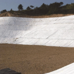
The excavator bucket cuts straight into the ground, creating a trench held tightly within a width of 450 mm to 600 mm. Workers unroll a 1.8-meter-wide continuous-filament nonwoven geotextile. This 110 g/m² material leaves 400 mm of extra fabric on each side of the trench. The fabric drapes over the trench edges like two wings, and the bottom and sidewalls must sit tight against the soil with no gaps greater than 30 mm.
This type of nonwoven fabric usually has an equivalent opening size of around 0.15 mm, just enough to stop clay particles larger than 0.002 mm. At 110 grams, it provides about 400 N of grab strength, so it will not tear easily even if stone falls onto it from a height of one meter.
- Avoid sharp roots on the ground when unrolling the fabric
- Overlap length must not be less than 300 mm
- Keep trench bottom level tolerance within 20 mm
- Temporarily hold the side fabric in place with bricks or stones
A dump truck unloads washed 19 mm single-size stone along the trench edge, and workers shovel in the first bedding layer, 50 mm to 75 mm thick, at the bottom. Dust content in this stone must be below 2%, otherwise the lower fabric layer can become sealed with fines within a month. The void ratio between the stones remains around 35%, providing the physical space needed for water storage.
Lay a 100 mm perforated PVC pipe flat on the stone bedding. The holes in the pipe wall must face downward at the 4 o’clock and 8 o’clock positions so that water can enter the pipe as soon as the water level begins to rise. A standard perforated pipe can discharge 150 liters of water per minute, depending on the capacity of the downstream storm inlet.
- Never place the perforations facing upward, which causes water to pond
- Maintain a minimum slope of 10 mm drop per meter of pipe
- All joints must use matching sealant or locking connectors
- Install a rodent guard at the pipe outlet
The next stage of stone backfill must fully bury the pipe until the stone reaches 300 mm above the top of the pipe. A stone layer of this thickness provides strong support for the backfill behind the wall and creates a broad channel for water flow. Every 150 mm lift of stone should be compacted once with a 70 kg lightweight compactor to prevent later settlement.
Under gravity, water behind the wall will move vertically downward through this 300 mm stone layer. Without full wrapping, soil particles will be carried by the water into the stone voids, reducing the original 35% void ratio to less than 5%. Once the stone turns into “mud-packed aggregate,” drainage capacity can collapse from 100 liters per second to less than 2 liters per second.
- When backfilling stone, bucket dump height must not exceed 0.5 meters
- No wood chips or sod may be mixed into the stone
- Avoid direct impact on the PVC pipe during compaction
- Continuously check that the fabric has not shifted during filling
Fold the 400 mm of fabric left on the left side over the top of the stone, then pull the fabric from the right side across to cover it. The two layers create an overlap zone more than 300 mm wide at the top of the stone fill. This overlap does not need glue or stitching—the weight of the 200 mm cover soil above is enough to seal the joint shut.
This “burrito wrap” physically isolates the drainage system from the surrounding soil. Water can pass into the stone layer like it is moving through a sieve, while soil particles are firmly kept outside the polyester fibers. Even during extreme storms with rainfall of 50 mm per hour, the stone inside can remain as clean as it was on the day it was installed.
- The top fold should follow the rule of overlapping from high ground toward low ground
- Do not use nails or rebar to pin through the overlap area
- Surface cover soil must be compacted to more than 90%
- Check whether any stone is exposed at the folded seams
If this fabric layer is omitted, hydrostatic pressure behind the retaining wall will build quickly. For a wall 1.2 meters high, trapped water can create more than 2000 kg of additional thrust per linear meter. That force is equivalent to a fully loaded pickup truck constantly pushing outward on the wall, causing weak concrete blocks to bulge or even break apart.
The cost of buying a little over one hundred square meters of geotextile is usually under $300, or only about 1.5% of the total retaining wall budget. But without this step, clearing clogged pipe and rebuilding the wall two years later can cost more than $5,000. In any landscape project, that kind of cost-benefit ratio should be a top priority.
- The vertical stone drainage layer must also be at least 300 mm thick
- At the top of the wall, leave enough fabric to form a wrapped edge that prevents soil loss
- Never use woven geotextile with poor permeability
- The drain pipe outlet must discharge directly to the outside face of the wall or connect into the main line
To check stone cleanliness, grab a handful and rub it in your palm—your hand should not be left coated in heavy mud dust. Use a level to verify slope at the pipe joints and make sure water can drain outward on a 2% grade.
For the final topsoil backfill, keep the excavator teeth at least 300 mm away from the fabric. Workers can spread the soil with a wooden rake, then install sod or decorative pebbles. The entire system works quietly underground, keeping the soil behind the wall dry and stable instead of saturated and ready to fail.
Practical Advice
Standing in a muddy retaining wall excavation with a roll of 110 g/㎡ continuous-filament nonwoven fabric in your hands, you are holding the line that keeps the structure from collapsing within five years. I have seen too many projects try to save money by skipping a few rolls of fabric, only to turn into expensive junkyards when the rainy season arrives.
In 2026, a 1.8-meter-wide, 100-meter-long roll of geotextile typically costs between $200 and $300. For a retaining wall 30 meters long and 1.2 meters high, that is still less than 2% of the total material cost.
High-quality nonwoven fabric typically has an AOS of about 0.15 mm. That means it can hold back sand particles larger than 0.15 mm while allowing 0.002 mm clay particles to wash out slowly with the water, preventing a cemented layer of fine sediment from forming on the fabric surface.
The 450 mm drainage trench cut behind the wall by the excavator is the container for the entire system. When laying the geotextile into it, I always insist that workers leave at least 400 mm of extra fabric at the trench top, because that determines whether the final “burrito” can be wrapped tightly enough.
If the fabric left on each side is less than 200 mm, it can slip downward during backfill compaction. Once even a 10 mm gap opens up, tons of clay behind the wall will force their way through the opening into the stone layer.
- Use continuous-filament nonwoven fabric with 50% elongation
- Keep trench bottom elevation variation within 20 mm
- Do not step on the fabric in studded construction boots during installation
- Joint overlap width must be maintained at no less than 300 mm
The 50 mm-thick layer of 19 mm single-size stone placed at the trench bottom serves as the base for the drain pipe. This stone must be washed. If dust content exceeds 2%, the lower geotextile layer can lose permeability after the first major storm.
A 100 mm perforated PVC pipe is then set on the bedding layer, with two rows of perforations facing the 4 o’clock and 8 o’clock positions. This allows water to drain away as soon as it rises to the pipe invert, instead of forming stagnant water at the bottom of the stone layer.
A 100 mm rigid perforated pipe that meets ASTM standards can carry about 150 liters of water per minute at a 1% slope. By contrast, flexible corrugated pipe with a sock tends to deform easily under gravity backfill, often reducing the effective flow area by more than 30%.
For every additional 300 mm of water buildup behind a retaining wall, hydrostatic lateral pressure on the base structure rises dramatically. If drainage fails behind a 1.2-meter wall, each meter of wall can end up carrying nearly 2000 kg of additional horizontal thrust—more than enough to push over standard interlocking concrete blocks.
The washed 19 mm stone used as backfill provides about 35% void space. Once the stone layer is filled to 300 mm above the pipe, a large underground reservoir has effectively been created.
Workers compact the stone in lifts using a lightweight compactor in the 60 kg range, making one pass every 150 mm. This prevents later stone settlement that could pull apart the geotextile seam above.
- The stone layer must extend vertically to within 300 mm of the top of the wall
- No excavated soil containing organic matter may be mixed into the stone
- The horizontal tolerance of the stone backfill must not exceed 50 mm per 10 meters
- During compaction, the machine should stay 150 mm away from the PVC pipe wall
To close the “burrito,” first fold the 400 mm flap from the higher side flat across the top of the stone, then bring the fabric from the opposite side over it. The two layers overlap directly over the centerline of the stone, and the overlap width must be locked in at 300 mm.
This physical overlap relies on the weight of the 300 mm-thick topsoil layer above. Under cover soil weighing 1.8 tons per cubic meter, the friction between the two fabric layers is enough to keep the seam closed even under flowing water.
If the crew cuts corners and installs only a sock-wrapped pipe, the entire stone layer is left directly exposed to the soil. After five years, the stone void ratio can drop from 35% to less than 10%.
I once took apart a collapsed brick wall and found that the stone inside had turned into hard, cement-like lumps. The nonwoven fabric, which originally allowed 100 liters per second per square meter to pass, had dropped to less than 5 liters per second after the surrounding soil clogged it because only the pipe had been wrapped.
When placing geotextile on the vertical face behind the wall, I temporarily fasten it with self-adhesive waterproofing fasteners. The vertical fabric should continue all the way up to 150 mm below the surface turf, creating a complete protective shell.
This step is skipped in most low-cost jobs, allowing black garden soil to wash down through the joints. The humus in that topsoil acts like glue, sealing off the top of the stone layer and causing the entire “burrito” system to fail from the top down.
- The vertical drainage stone band should be 300 mm to 450 mm thick
- At the wall top, the geotextile should be folded outward by 150 mm
- Weep holes should be spaced at 1.2 meters
- Each weep hole should be lined on the inside with insect screen
All told, building a fully wrapped drainage trench takes about 30% more labor time than simply burying a drain pipe. For an experienced crew, that usually means just two extra hours to clean the trench and align the seams.
If this step is not done properly, any later wall lean or cracking will cost more than three times the original construction price to repair. When you have 110 g/㎡ continuous-filament fabric in front of you, any excuse about the pipe already having its own filter sock is just borrowing against the wall’s lifespan.
No Outlets
Common Pitfalls
Many installers bury a 100 mm perforated drain pipe in stone and then leave the pipe end sealed in the backfill. That turns the drain pipe into a storage pipe. Once it fills with water, the water seeps back into the surrounding soil. When soil moisture rises from 15% to 35%, the added weight can create as much as 2500 kg of lateral thrust per linear meter. That exceeds the load capacity of most residential retaining walls.
Perforated pipe typically has 30 to 50 holes per meter, each about 10 mm in diameter. Without an external outlet, standing water inside the pipe accelerates the settlement of fine particles smaller than 0.02 mm. Those particles build up into a sludge layer more than 20 mm thick at the bottom of the pipe, permanently sealing the intake holes. This kind of failure often becomes obvious during the first rainy season after construction.
- Use 100 mm HDPE double-wall corrugated pipe for better compressive strength.
- The pipe outlet must extend at least 150 mm beyond the side face of the wall.
- Never run the drain pipe directly into dense clay with no discharge path.
- Use proper connectors at joints to prevent leaks through gaps wider than 5 mm.
- Maintain a drainage slope between 1% and 2%.
Another common mistake is using cheap landscape weed barrier, around 40 g in weight, instead of professional nonwoven geotextile in the 140 g to 200 g range. Weed barrier typically has a permeability below 20 L/min per square meter. Professional geotextile exceeds 4000 L/min per square meter. Low permeability causes water to build up on the outside of the fabric, creating localized seepage pressure above 5 kPa.
That pressure forces fine sand from the soil into the fabric fibers. Once more than 60% of the fiber voids are blocked, the drainage layer loses its flow function entirely. Water is then forced to escape through joints in the wall, creating structural cracks wider than 2 mm in the face. This is especially obvious during storms with rainfall above 50 mm.
- The AOS of the nonwoven geotextile must be less than 0.212 mm.
- The stone layer must remain at least 300 mm thick to provide enough collection space.
- Geotextile overlaps should be 30 cm wide and secured with tape.
- Avoid stone larger than 40 mm to prevent puncturing the fabric fibers.
- Construction vehicles must never drive directly over installed geotextile.
| Pitfall Type | Incorrect Practice | Correct Technical Standard |
|---|---|---|
| Pipe End | Buried in soil or sealed shut | Extend more than 150 mm beyond grade |
| Fabric Selection | Use weed barrier with permeability < 50 L/min | Use geotextile with permeability > 4000 L/min |
| Weep Hole Layout | Spacing over 3 m or no holes | Spacing 1.2 m to 1.8 m, diameter 50 mm |
| Outlet Slope | 0% flat or reverse slope | 1% to 2% downward gravity slope |
If a gravity retaining wall does not have 50 mm weep holes, the stone layer behind it effectively becomes a giant water bag. Every 1 meter increase in water height adds 10 kPa of pressure at the base of the wall. For a 2-meter wall, total thrust under full saturation is three times higher than in dry conditions. That difference in pressure can push the wall base out of alignment in a short time.
Weep holes are often installed too low, beneath the first course of blocks. That leaves the bottom 200 mm of stone permanently submerged, weakening the bearing capacity of the foundation. Field testing shows that long-term saturation can reduce soil shear strength by more than 40%. Weep holes must be installed above the first course and connected directly to the 20 mm washed stone layer behind the wall.
- Install one 50 mm PVC weep pipe every 1.5 meters.
- Tilt the outlet outward at 5 degrees to prevent rainwater backflow.
- Add 10 mm filter stone on the inside of the pipe to prevent clogging.
- The wall face outlet should sit 100 mm above finished grade.
- Periodically clear internal buildup using 5 mm steel wire.
Outlets buried under landscaping are a common maintenance failure. A 100 mm layer of mulch or decorative stone increases discharge resistance. When the pressure differential at the outlet falls below 2 psi, water trapped in the pipe can no longer discharge. Over time, a 50 mm-thick humus layer can form at the pipe end and completely seal the outlet.
If the drain pipe outlet is not fitted with a rodent screen, biological clogging can occur. Small animals about 30 mm in diameter may crawl in and build nests, blocking more than 70% of the pipe cross-section. During a heavy storm, flow can spike from 5 L/min to 50 L/min, and nest debris will quickly lodge in bends and block the line.
- Install 3-mesh-per-inch stainless steel screen at the outlet.
- Place 0.5 square meters of riprap below the outlet for erosion control.
- Remove all plant roots within 30 cm of the outlet.
- Perform pressure-flush inspections every April and October.
- Place the outlet away from foundation bearing zones to avoid localized soil softening.
If the backfill is compacted to less than 95%, large amounts of surface water can infiltrate downward. In rainy weather, each square meter of uncompacted area can allow more than 15 liters of surface water to enter. That runoff washes across the geotextile surface, and particles smaller than 0.05 mm can form a dense mud skin about 3 mm thick. This mud layer has extremely low permeability and can cause the drainage system to fail within two years of service.
The absence of an interceptor drain at the top of the wall is another overlooked factor. Slope runoff can wash directly over the wall crest, causing more than 10 mm of soil loss. That sediment enters the stone filter layer behind the wall and can reduce its 35% void ratio to about 10% after a single rainy season. Once the voids are filled, the drain pipe loses its ability to collect water.
- The top 30 cm should be sealed with low-permeability clay.
- The interceptor drain should be at least 150 mm deep and 300 mm wide.
- Slope vegetation cover should exceed 90% to reduce sediment loss.
- Drain pipe joints should be sealed with aging-resistant adhesive.
How to Identify the Problem
In dry weather, white powdery crystals may appear on the wall face, usually between 0.5 mm and 2 mm thick. This happens when trapped water behind the wall seeps through the concrete blocks, dissolves free lime in the material, and deposits it on the surface. If these crystals cover more than 15% of a local wall area, the internal stone layer has likely been at full saturation for a long time.
Forty-eight hours after rain, the joints at the base of the wall are still weeping while the drain pipe outlet remains dry. At that point, soil saturation behind the wall is often above 90%. A properly functioning system should drain free water within 120 minutes after rainfall stops. For every 1 meter increase in trapped water height, lateral pressure rises by about 10 kN per square meter.
Check the vegetation within 300 mm above the base of the wall. Moss or mildew that favors wet conditions suggests that relative humidity in that zone has been above 85% for an extended period. If the soil at the toe of the wall feels noticeably softer than soil farther away and your foot sinks more than 20 mm when stepped on, the bottom drainage path has likely been physically cut off.
Use a level to measure wall plumbness. If the lean exceeds 1% to 2%, or if the top of a 2-meter wall has moved outward by more than 20 mm, the cause is usually additional loading from trapped water. That displacement shifts the structure’s center of gravity off the support centerline and increases overturning risk by more than 30%.
| Observation | Normal Drainage Performance | Failure Signs with No Outlet |
|---|---|---|
| Wall seepage duration | Disappears within 6 hours after rain stops | Stays wet for 48 – 72 hours after rain stops |
| Efflorescence area | Less than 2% of total wall area | More than 15% of total wall area |
| Settlement behind wall | Less than 5 mm per year | More than 50 mm of sudden collapse |
| Weep hole flow | Velocity reaches 0.5 m/s during heavy rain | No discharge at all, or only dripping |
Funnel-shaped sinkholes 50 mm to 150 mm in diameter may appear in the backfill area behind the wall. This happens when trapped water searches for an escape path and carries fine sand out through gaps in the geotextile seams. These voids can reduce the overall bearing capacity of the backfill zone by 40% and lead to cracks wider than 3 mm in the surface paving.
Woody seedlings more than 5 mm in diameter growing out of the wall joints are another warning sign. Their roots grow toward the moist stone layer behind the wall, further damaging the geotextile. Once the roots reach 10 mm in diameter, the expansion pressure can force open the mortar joints between retaining wall units.
Check the drain pipe outlet for sediment buildup. If more than 20 mm of fine mud has collected there, the geotextile filtration function or the integrity of the wrap has failed. Once sediment enters the pipe, it can occupy more than 30% of the pipe diameter, cutting flow velocity by 50% and causing internal blockage.
- Prepare a standard 20 L bucket.
- Pour the full bucket into the observation port or cleanout behind the wall.
- Record how long it takes for water to appear at the drain outlet; normal delay should be under 30 seconds.
- Measure the discharged volume. If recovery is below 80% (less than 16 L), water is being retained in the stone layer.
- Check the turbidity of the discharged water. If sediment makes up more than 5%, the filter layer has been damaged.
In cold climates, failed outlets allow water to collect in the stone layer and freeze in winter. Water expands by about 9% when it freezes. That expansion can impose tensile stress on 140 g/m² geotextile beyond its design limit, causing the fibers to rupture and the fabric to lose its filtering function.
Horizontal joints in the middle of the wall may develop tensile cracks up to 2 mm wide. When trapped water rises to half the wall height, the bending moment at the base increases by 2.5 times. This uneven load distribution can force the structure into shear failure, with cracks typically extending diagonally upward at a 45-degree angle.
Thermal imaging can also be used to observe wall surface temperature patterns. Areas with drainage failure hold more water and therefore have greater thermal inertia. Three hours after sunset, those zones are usually 2 to 4 degrees Celsius cooler than dry areas. This temperature map can pinpoint where water is accumulating inside the wall.
- Surface water behind the wall exceeds 10 mm in depth and remains for more than 1 hour.
- A dark damp halo about 100 mm wide appears around the weep holes.
- The drainage slope at the wall toe reverses by more than 3 degrees.
- The inside wall of the drain pipe has biofilm or oily buildup thicker than 2 mm.
Check the wall joints for rust-colored staining. This indicates that water has been washing minerals out of the soil and lingering inside the wall long enough for oxidation to occur. If the stain extends more than 200 mm, the porosity of the internal drainage system has likely dropped below 20% of its original design value.
Long-term water accumulation also reduces the shear strength of the foundation soil beneath the geotextile. Laboratory data shows that the friction angle of cohesive soils drops by 5 to 10 degrees under saturated conditions. This directly reduces the wall’s sliding safety factor from the standard 1.5 to the critical threshold of 1.0.
Proper Setup
Installing a 100 mm perforated drain pipe is the foundation of drainage balance at the base of the wall. This high-density polyethylene (HDPE) pipe has intake holes 10 mm to 12 mm in diameter distributed across its surface, with a total intake area of at least 2500 square millimeters per linear meter. The perforations must be placed facing downward on the leveling bed, so the water level only needs to rise 10 mm before it can enter the pipe.
If the holes face upward, the water level must rise past half the pipe diameter before drainage begins, leaving 50 mm of standing water in the bottom of the pipe. That trapped water continuously softens the foundation soil and can reduce its bearing capacity by more than 30%. In cold climates, the roughly 9% volume expansion from freezing is enough to crack the pipe wall or shift the wall base.
Pipe slope should be set between 1% and 2%, which means a drop of 10 cm to 20 cm over every 10 meters. That grade creates a gravity flow velocity of about 0.6 meters per second, enough to carry trace amounts of fine sand out of the pipe and prevent internal sediment buildup. A vertical cleanout riser should be installed at the upstream end, also with a 100 mm diameter, for future maintenance.
- Use Schedule 40 thick-wall PVC pipe, with enough compressive strength to support 2 meters of backfill above.
- Keep intake hole diameter below 15 mm so the stone layer can screen out larger debris.
- Use 45-degree bends instead of 90-degree elbows to reduce resistance and sediment buildup.
- Use gasketed joints so the pipe will not pull apart as the soil naturally settles.
- Place the pipe on a 50 mm layer of washed stone; never install it directly on native soil.
The drain pipe must be surrounded by washed stone about 20 mm in size, with a void ratio of roughly 35%. These voids act like a highway behind the wall, collecting seepage water and directing it by gravity. The fines content in the stone must be below 1%, otherwise mud will quickly fill the voids after rain and reduce drainage efficiency by more than 80%.
Geotextile selection typically falls between 140 g/m² and 200 g/m². Its AOS should be smaller than 0.212 mm, which effectively blocks particles larger than a No. 70 sieve and keeps backfill soil out of the stone. This nonwoven fabric should maintain a permeability of 0.2 cm per second, allowing more than 4000 liters of water per square meter per minute to pass through.
When wrapping the stone layer, leave at least 300 mm of overlap and secure it with U-shaped pins. If the overlap is insufficient, mechanical pressure during backfilling will open the seam. Once fine soil enters the stone and reduces porosity below 10%, hydrostatic pressure behind the wall can spike within 48 hours, adding several tons of horizontal force per square meter.
- The width of the vertical drainage stone column must not be less than 300 mm.
- The geotextile should have a grab strength greater than 500 N to resist puncture from sharp stone and prevent sand leakage.
- Backfill should be placed in 150 mm lifts and compacted to at least 95%.
- Heavy equipment must never drive directly over uncovered drain pipe during installation.
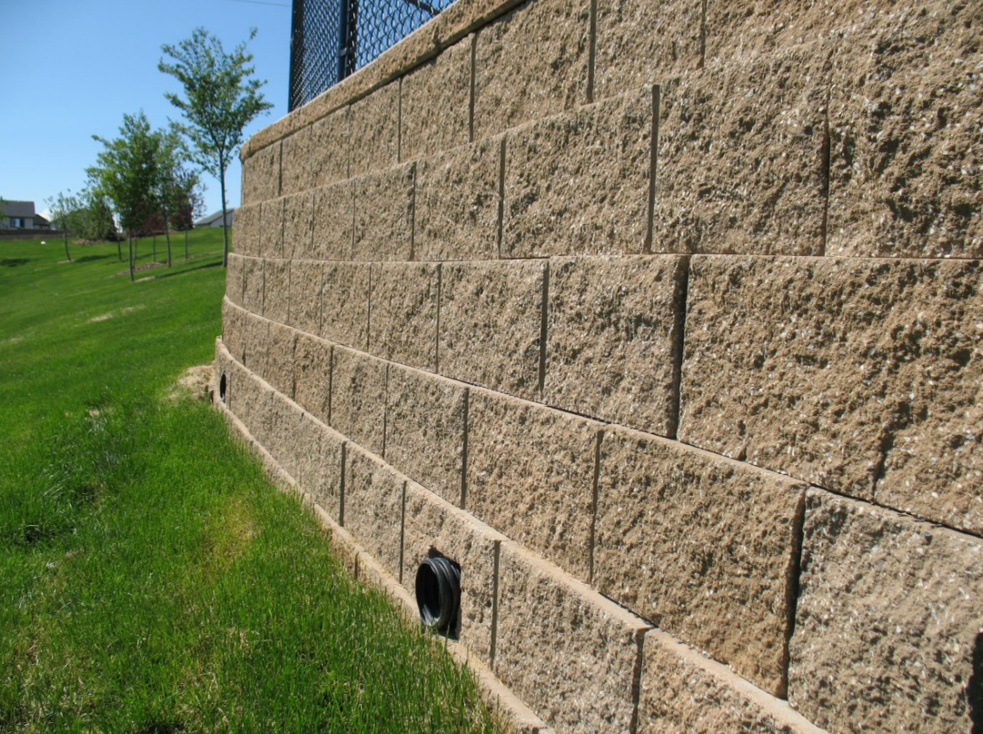
In concrete block or cast-in-place walls, weep holes serve as the second safety lock in the drainage system. A 50 mm weep hole should be installed every 1.2 to 1.8 meters. The pipe invert must be level with the bottom of the stone layer behind the wall. If placed too high, water will collect at the base of the wall and keep the lower corner saturated.
The condition of the internal system can be judged by watching the weep holes. A 50 mm weep hole at full flow can discharge about 30 liters of water per minute. If large areas of white staining appear on the wall after heavy rain, meaning calcium carbonate efflorescence, water is not escaping through the designed openings and is instead being forced through the wall joints. That usually means the internal geotextile has been sealed by silt.
- A sloped deflector can be installed at the outside of the weep hole to keep water from running straight down the wall face.
- Place coarse stone on the inside of the pipe opening so the geotextile does not press tightly against it and restrict flow.
- The outlet should be set 50 mm above exterior finished grade to prevent surface water backflow.
- Clean debris from inside the holes every six months with a wire brush.
The end of the drain pipe must discharge into open air—that is, to an exposed outlet at the ground surface. The outlet is usually located in a lower-sloped lawn area or at a storm inlet. It should sit about 150 mm above grade to keep weeds and soil from burying it. Installing a 3-mesh-per-inch stainless steel screen is essential to keep rodents from entering the pipe and nesting inside.
Energy dissipation below the outlet is often overlooked. Water discharging from a 100 mm pipe has enough kinetic energy to erode the soil at the wall base and undermine the foundation. It is recommended to place riprap covering about 0.5 square meters below the outlet, using stones at least 100 mm in size. These stones spread the flow and convert erosive force into more even seepage.
- The pipe should extend at least 150 mm beyond the wall face so water cannot run back toward the footing.
- Each spring, check whether the screen has been crushed by dead leaves or snow.
- Provide a 5% reverse slope around the outlet to direct surface water away from the retaining wall foundation.
- Do not plant deep-rooted trees along the drainage path.
When soil moisture rises from 15% to 30%, the lateral pressure it exerts on the wall increases geometrically. Physical data shows that a fully saturated 1.8-meter wall can be subjected to more than 2500 kg of thrust per linear meter. That pressure will cause the top of the wall to move. If the wall top is found leaning outward by more than 5 mm, the outlet must be checked immediately for blockage.
Under rainfall intensity of 25 mm, if there is still no visible discharge from the drain outlet four hours after the rain stops, the flow is being blocked somewhere between the geotextile and the stone layer. That indicates system failure and calls for inspection with an industrial borescope inserted into the pipe. In a properly functioning system, flow should continue steadily after rain until the water level behind the wall returns to equilibrium.