
Three drainage mistakes to check behind a retaining wall are an incompatible filter, an unprotected soil–aggregate interface and a drain with no functioning discharge path. A thicker geotextile or a pipe sock cannot correct all three. Diagnose the water source and the complete flow route before replacing materials. A wet patch alone does not identify the failed component.
This article is a troubleshooting checklist for contractors and site inspectors. For a new material purchase, use the separate woven vs. nonwoven retaining-wall selection guide. New bulging, fresh structural cracks, rapid movement or ground loss requires a qualified assessment; do not excavate behind a distressed wall or force water into its drains to investigate.
1. Using the wrong fabric or approving it from appearance alone
“Woven” does not automatically mean impermeable
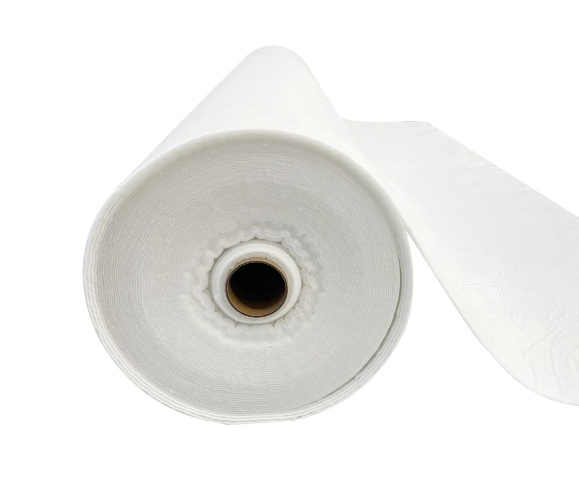
A woven slit-film separator and a woven filter made for drainage are not interchangeable descriptions. Likewise, a needle-punched nonwoven does not become a suitable filter simply because it feels thick. Check the installed product against the approved filter specification, including the test methods and reporting units.
FHWA rockery guidance excludes woven slit-film separation fabric in its specified rockery filter detail. The restriction is specific to that application; it should not be expanded into a claim that all woven geotextiles are unsuitable for water flow.
| Check | Evidence to collect | What the result can establish |
|---|---|---|
| Product identity | Roll label, grade, batch and approved submittal | Whether the installed material matches the approved product |
| Soil compatibility | Retained-soil gradation, fines content, plasticity and filter criteria | Whether the opening and hydraulic selection were evaluated for the actual soil |
| Hydraulic data | Permittivity in s⁻¹; flow per area with test head | Whether the data are comparable; a value in gpm is not permittivity |
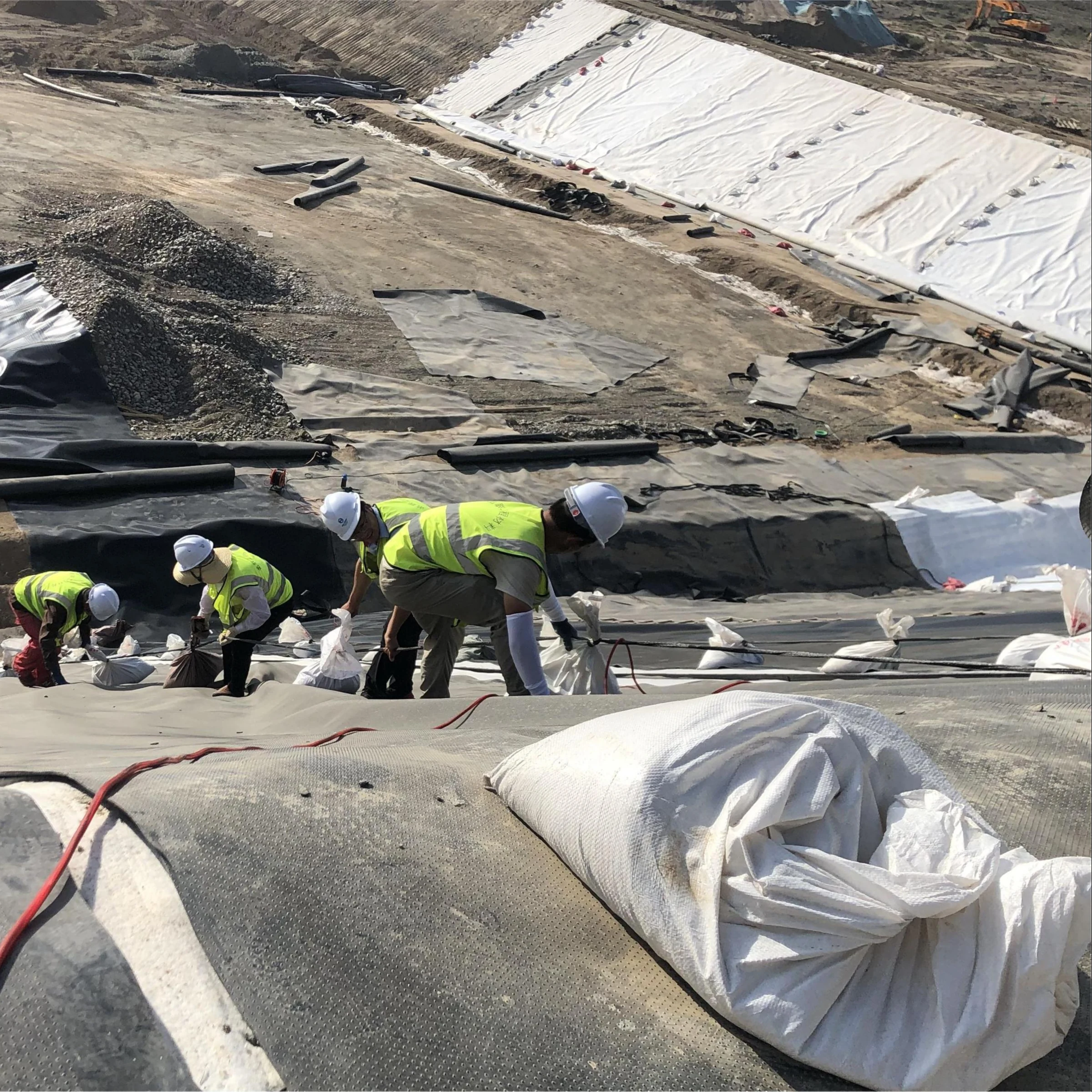
| Installation damage | Accessible tears, displaced seams, mud-loaded surfaces and photographs before cover | Whether water or soil can bypass the intended filter interface |
Check the soil–fabric combination
Do not select an opening from drainage-stone size alone or assume that a 0.15 mm opening mechanically stops every clay-sized particle. Filtration depends on the interacting soil and fabric, not a simple promise that all particles smaller than one opening are excluded. The filter-cloth AOS and hydraulic guide explains the data needed for this check.
Where clogging or soil loss remains uncertain, testing may be required with representative site soil. ASTM D5101-23 evaluates soil–geotextile compatibility under unidirectional saturated flow. Its scope distinguishes soils with plasticity index below 5 from those at or above 5, for which it recommends the D5567 approach. The laboratory and designer should select the applicable investigation; a bucket-pour demonstration is not an equivalent acceptance test.
Thicker is not a diagnosis
Replacing a clogged fabric with a heavier grade can leave the same incompatibility unresolved. Equally, replacing it with a lighter grade may reduce installation resistance. Examine retention, flow and survivability separately. There is no supported universal percentage by which a particular fabric weight reduces cracking, increases pipe capacity or extends wall life.
2. Wrapping the pipe while leaving the soil–aggregate interface unprotected
What the “burrito wrap” can and cannot do
A sock around a perforated pipe acts at the pipe surface. If soil can enter the surrounding drainage stone, the stone may become contaminated even while the pipe sock remains intact. The filter therefore needs to be considered at every relevant soil–drainage interface, according to the wall detail.
This does not mean every wall requires a fully wrapped trench plus a pipe sock. Some designs use a specified geotextile along selected interfaces, a graded mineral filter, or another engineered drainage arrangement. The CMHA segmental-wall guide describes a geotextile filter between gravel and infill in some cases; the actual system detail determines the required extent.
| Possible defect | Inspection question | Correction to develop with the designer |
|---|---|---|
| Exposed soil against drainage stone | Does the detail require a filter here, and was it installed? | Restore the specified interface; assess contaminated stone rather than covering the defect |
| Open top or displaced overlap | Could backfill or construction runoff enter the drainage zone? | Re-establish the specified closure and control sediment during placement |
| Fabric stretched over a hollow | Can water carry soil through a gap under the fabric? | Restore support and contact without damaging the wall or undermining its foundation |
| Pipe sock used as the only filter | Is the surrounding aggregate protected where required? | Review the full soil-to-outlet flow path instead of adding fabric indiscriminately |
Measure the wrap from the approved cross-section
Where a full rectangular wrap is actually specified, a cutting check can avoid short top flaps. For an illustrative 0.45 m-wide by 0.45 m-deep envelope with a specified 0.30 m top overlap, the idealized cross-section requires:
Fabric width = 2 × width + 2 × depth + overlap = 2 × 0.45 + 2 × 0.45 + 0.30 = 2.10 m.
This is a geometry example, not a recommended trench size or overlap. Allow for the actual profile, corners, placement slack and the approved details; longitudinal joints need their own allowance. A roll width of 1.8 m would not provide the assumed top overlap in this example.
- Inspect contact, tears, patches, transitions and overlap continuity before cover.
- Use clean specified aggregate and prevent muddy runoff from entering during construction.
- Record the position and product identity before the filter becomes concealed.
- Do not torch-bond overlaps or improvise adhesive closures unless an approved system explicitly permits that method.
3. Installing a drain without a functioning outlet
Trace the route from water source to discharge
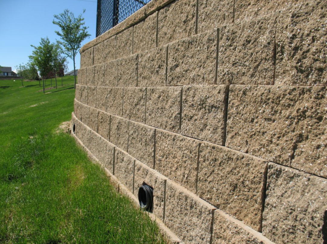
A perforated pipe is not a complete drainage system. It needs the specified position, grade, connections and discharge arrangement. An outlet can be ineffective because it is buried, obstructed, submerged, damaged, connected incorrectly or higher than the intended collection level. Pipe diameter alone does not establish flow capacity.
Allan Block water-management guidance distinguishes incidental drainage within its wall system from primary management of concentrated surface water and groundwater. A downspout, swale or new paved area draining toward the wall can therefore require a site drainage change, not simply a larger backdrain.
Why trapped water matters: pressure and force are different
For a simple illustration, assume fresh water is stationary behind a vertical face, there is no balancing water on the front, and water head above the base is h. With water unit weight 9.81 kN/m³, bottom pressure is p = 9.81h kPa and the triangular water load per metre of wall is P = ½ × 9.81h² kN/m.
| Water head h | Bottom water pressure | Water force per metre of wall |
|---|---|---|
| 0.6 m | 5.89 kPa | 1.77 kN/m |
| 1.2 m | 11.77 kPa | 7.06 kN/m |
| 1.8 m | 17.66 kPa | 15.89 kN/m |
These are calculated examples, not site measurements or a wall-stability check. They exclude earth pressure, surcharge, seismic effects and seepage complications. They show why a pressure in kPa or lb/ft² must not be confused with a total load per metre or foot of wall. The underlying idealization is pressure increasing linearly with depth below a stationary water surface; see the USACE HEC discussion of hydrostatic and pore-water forces for the broader hydraulic context.
Separate symptoms from proof
| Observation | What it may indicate | What it does not prove |
|---|---|---|
| Little outlet flow during or after rain | Low inflow, blockage, disconnected pipe or a different flow route | That the fabric alone is clogged |
| Sediment at an outlet or local settlement | Possible soil migration or contamination needing investigation | A specific percentage loss of soil or pipe capacity |
| Wet patches or efflorescence | Water movement and possible dissolved salts | A measured pore pressure or a unique failure cause |
| New lean, bulging, cracks or ground loss | Potential structural or geotechnical distress | That a simple drain clean-out will make the wall safe |
Restore the system using a documented repair plan
- Review drawings, construction photographs, drain routes and changes in surface runoff.
- From a safe accessible position, record outlet locations, obstructions, visible damage and the timing of wet areas.
- Have the responsible designer or drainage specialist determine whether surveys, pipe inspection or ground investigation are needed.
- Correct the identified obstruction, connection, filter or runoff defect using a plan that preserves wall support.
- Document the repair and verify discharge under an agreed inspection or test procedure. Keep outlets accessible for maintenance.
Do not use a generic “20 litres in, 16 litres out within 30 seconds” rule to accept a perforated drain: water can enter or leave along its length. Likewise, 1–2% grade means 10–20 mm fall per metre, but is only appropriate when required by the approved design. Neither conversion establishes pipe capacity.
When requesting a replacement nonwoven geotextile, provide the original specification, soil information, observed defect and required test values. This keeps material selection connected to the diagnosed problem rather than promising an unsupported percentage improvement.