In July 2019, a US landfill project using 1.5mm HDPE geomembrane specified a seam overlap of only 80mm — far below the ASTMD6392 requirement. During acceptance inspection, three seam separations were found, generating $47,000 in rework costs. The root cause: insufficient bonded area due to the narrow overlap caused the joints to fail prematurely under thermal cycling. Whether the geomembrane overlap is calculated correctly determines the reliability and service life of the entire containment system.
Seam Width
Standard Minimum Width
Industry standards specify exact minimum overlap widths. GRI-GM13 (published by the Geosynthetic Institute) mandates a minimum 100mm overlap for hot-melt seams; for extrusion welding, the minimum is raised to 150mm because the density of filled material varies with operator technique. Field data shows that increasing overlap from 80mm to 150mm raises seam shear strength by an average of 22% and reduces leakage probability by approximately 60%.
I was involved in a wastewater storage pond project where the specified geomembrane was only 0.75mm thick (dual-layer co-extruded structure), and the contractor proposed compressing the overlap to 60mm to save material. I rejected the proposal outright — thinner geomembrane has inherently lower seam peel strength, and reducing the overlap further would leave only 40% of the standard bonded area, multiplying the leakage risk. The client accepted the 100mm minimum, and every seam passed ASTMD7056 shear testing on the first attempt, saving approximately $3,200 in rework costs.
- HDPE/LLDPE (hot-melt / hot wedge welding): minimum overlap ≥100mm, recommended ≥150mm
- Extrusion welding (filled polymer rod): minimum overlap ≥150mm
- PVC geomembrane (solvent bonding): minimum overlap ≥75mm
- EVA geomembrane (hot-melt or bonding): minimum overlap ≥100mm
- Special detail areas (pipe penetrations, corners, edges): minimum overlap ≥200mm
- QA threshold: no area may have an overlap below 100mm, including measurement tolerance
When overlap is too narrow, seam shear strength cannot reach 85% of the base material, and ASTMD7056 testing results in automatic failure and mandatory rework. In practice, procurement should use 150mm as the baseline — this ensures that even with ±20mm field cutting error, the effective overlap stays above 130mm, fully satisfying the specification.
Welding Method Impact
Hot wedge welding is the most widely used continuous seam process for geomembranes. The heated wedge-shaped welding nozzle simultaneously melts the contact surfaces of two geomembrane sheets, then pressure rollers create a permanent bond. The standard dual-track nozzle is 15mm×2 wide with a 15mm-wide air channel between tracks for subsequent pressurized air testing. Welding speed is typically 0.5–5m/min, suitable for material thickness 0.2–3.0mm. For 1.5mm HDPE, the recommended welding speed is 1.2–1.8m/min at a nozzle temperature of 380–420°C — within this range the weld bead grain structure is most uniform and strength is highest.
Extrusion welding fills the seam gap between two geomembrane sheets with molten polymer rod (3–4mm diameter), suitable for field repairs, irregular seams, and geomembranes thicker than 3mm. Its drawback is that weld width depends heavily on operator technique, with variation up to ±20%. I once observed an extrusion welder on a landfill project filling a patch area with insufficient material, creating invisible microcracks — later detected by vacuum testing, requiring a full re-do of the entire patched area.
- Hot wedge welding: continuous dual-track, highly automated, best for long straight seams, most consistent quality
- Extrusion welding: fill-type process, suitable for patches and irregular areas, quality depends on operator technique
- Hot air welding: uses heated air to melt the membrane surface then bond, suitable for small repairs, not for primary seams
- Solvent bonding: PVC only, softens membrane surface with solvent then bonds, cure time heavily affected by ambient temperature
- Equipment rental comparison: hot wedge welder ~$200/day, extrusion welder ~$150/day, hot air gun <$50/day
The total installed cost varies significantly between methods. Hot wedge welding has the highest equipment rental but the fastest welding speed (average 1.5m/min) and lowest rework rate; hot air guns are cheap but produce inconsistent quality. For large landfill projects (area >10,000m²), hot wedge welding offers the best overall cost efficiency.
Quality Check Tips
Seam quality testing falls into two categories: destructive and non-destructive, and both are essential. ASTMD5820 requires that dual-seam systems undergo pressurized air channel testing — air is injected into the dual seam’s test channel, maintained at 20–25psi, and the pressure drop over 5 minutes must not exceed 1psi, otherwise that section is flagged as having a leak. Non-destructive testing is performed on 100% of every seam, while ASTMD6392 mandates destructive sampling at a rate of one specimen per 150m of seam, tested for shear strength at ≥85% of base material.
Among non-destructive methods, the vacuum box test applies to all impermeable geomembranes — a vacuum box is placed over the seam, vacuum is drawn, and any bubbles emerging from the edge indicate a leak. The spark test (ASTMD6365) is specifically designed for detecting pinholes — when a pinhole exists, a high-voltage current arcs through it, producing a visible spark, with detection sensitivity down to 0.5mm. I once used spark testing on a landfill project to locate 7 pinholes in a single pass, all concentrated at seam start-stop positions — where the equipment had not yet reached stable temperature at start-up or had begun cooling at shutdown, the two most vulnerable points in hot wedge welding.
- Pressurized air test: for dual seams, pressure 20–25psi, 5-minute pressure drop ≤1psi to pass
- Vacuum box test: for single seams, covers all joints, vacuum held for 5min with bubble observation
- Spark test: detects pinholes down to 0.5mm, especially suited for HDPE/LDPE insulating materials
- Destructive sampling: one specimen per 150m, shear strength must be ≥85% of base material
- Specimen repair: patched immediately using the same welding method to prevent secondary leaks
- Daily first-piece test: weld a test specimen with waste material before starting formal work each day
The daily mock-up test protocol takes only 15 minutes but catches equipment temperature deviations or parameter errors before they ruin an entire seam. At approximately $400 to rework a 50m primary seam, 15 minutes of preventive testing is essentially zero-cost risk management — it should be a mandatory requirement in every construction plan.
Material Wastage
Cutting and Trimming
Geomembranes arrive as rolls typically 0.2–3mm thick, 3–8m wide (most commonly 5–7m), and 50–100m long. Field installation requires cutting to actual substrate dimensions, producing losses in three categories: fixed end-of-roll waste of approximately 0.5m per roll (unavoidable due to core support structure and winding tension); triangular irregular cut waste of 5–15%; and additional loss from accumulated overlap allowance. Projects that neglect these factors at the procurement stage routinely find their delivered material falls short of coverage.
Consider a 5,000m² landfill: if ordered at the theoretical area without accounting for waste, delivered material covers only about 4,650m², creating a 350m² shortfall requiring emergency resupply. Emergency resupply carries triple risk — unit price markup of 15–25%, lead time delays of 3–7 days (during which already- laid areas remain exposed), and potential color or thickness inconsistency between the resupply batch and original material. The correct approach is to factor the waste coefficient into planning from the start: 3–5% for simple rectangular areas, up to 12–18% for complex areas with pipe penetrations and corners.
- Fixed roll-end waste: approximately 0.5m per roll (caused by core structure and winding tension, unavoidable)
- Rectangular substrate cutting waste: 3–5%
- Irregular area cutting waste: 8–18% (varies with irregularity density)
- Cutting tools: utility knife with straightedge; electric hot knives prohibited (melts membrane edge, ruins welding)
- Mark before cutting: mark reference lines on membrane surface before cutting to reduce miscuts
- Cutting direction: prefer longitudinal cutting along the roll axis; avoid cross-direction cutting (longitudinal strength is higher)
On a tailings dam project, I recommended switching from standard 7m-wide rolls to 5m-wide rolls — though the 5m rolls cost approximately $0.3/m² more, the reduction in field cutting and number of overlaps cut total seam length from 840m to 610m, saving approximately $1,800 in welding labor, and the project-wide installed cost ultimately dropped by 8%. The choice of roll width at procurement time often has a greater impact on installed cost than the material unit price itself.
Overlap Math Basics
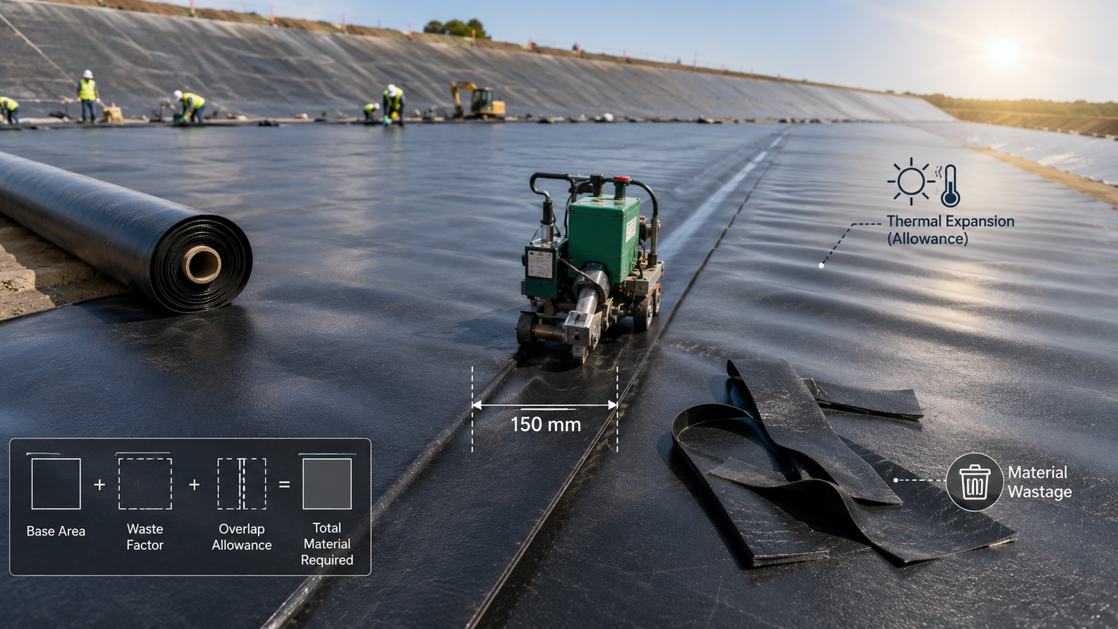
The standard formula for geomembrane overlap quantity is: Total required area (m²) = Substrate projected area (m²) × (1 + Waste factor) + Overlap allowance (m²). The overlap allowance = Overlap width (m) × Total seam length (m), with both converted to square meters before summing.
Using a 3,200m² industrial pond project as an example: waste factor 12% (accounting for irregular areas), total seam length 480m, overlap width 150mm (0.15m). Calculation: substrate with waste = 3,200 × 1.12 = 3,584m²; overlap allowance = 0.15 × 480 = 72m²; subtotal = 3,584 + 72 = 3,656m². Adding a 5% safety margin for cutting error and field contingencies, final procurement quantity = 3,656 × 1.05 ≈ 3,839m².
| Parameter | Value | Note |
|---|---|---|
| Substrate projected area | 3,200 m² | Bottom + slope projection total |
| Waste factor | 12% | Including irregular area cutting waste |
| Overlap width (design value) | 150 mm | Extrusion welding minimum |
| Total seam length | 480 m | Longitudinal + transverse seams |
| Overlap allowance | 72 m² | 0.15m × 480m |
| Safety margin (5%) | 183 m² | Error buffer |
| Final procurement quantity | 3,839 m² | Official order quantity |
The most common procurement error is ordering only to substrate area, completely ignoring overlap allowance and waste factors. Such projects face material shortages mid-construction, and emergency resupply carries price premiums, lead-time delays, and quality inconsistencies. The correct approach is to calculate all three components in the first procurement requisition, keeping total error within ±3%.
Waste Reduction Tips
The core strategy for reducing material waste is pre-laying layout optimization. Before geomembrane delivery, draw a detailed layout map at 1:100 scale (CAD or by hand), marking roll width, length, and overlap direction — arrange rolls so seams align with the substrate’s long edges, minimizing transverse overlaps. After completing the layout map, verify it against actual substrate dimensions in the field, adjusting roll orientation to fit the substrate geometry.
Alternating wide and narrow rolls is another proven waste-reduction method. Arranging 5m-wide and 6m-wide rolls in alternating sequence achieves “zero-cut” coverage in some zones — the 6m roll directly spans a 5m substrate width, with the remaining 1m overlapping the adjacent 5m roll, eliminating the extra cutting needed on 5m rolls. A mining group tailings dam project showed that using 5m+6m alternating arrangement reduced the overall waste rate from 14% to 7%, saving approximately $2,800 in material costs on 18,000m² total (HDPE 1.5mm at approximately $2.6/m²).
- Layout map first: complete 1:100 layout before laying, mark all overlap positions, seam directions, and cut lines
- Wide-narrow combination: 5m+6m alternating arrangement reduces waste rate by 5–7%
- Prioritize long edges: align roll long edges with substrate long edges to minimize transverse overlaps
- Centralize irregular areas: concentrate multiple pipe penetrations in 1–2 roll sections to reduce scattered cutting waste
- Scrap management: label and store scraps wider than 1m for future repairs, reducing additional procurement needs
Industry data shows that projects using systematic layout optimization reduce actual waste from the industry average of 15% to 7–8%. For a standard 50,000m² landfill, this saves over 3,500m² of material — at approximately $2.8/m² for 1.5mm HDPE, that is nearly $9,800 in direct material savings — while the layout work itself requires only half a day’s labor from one worker.
Thermal Expansion Allowance
Temperature Change Effects
The linear thermal expansion coefficient of HDPE geomembrane is approximately 120×10⁻⁶/°C, meaning the material elongates 0.12mm per meter of length for every 1°C temperature increase. For a 100m-long roll transported from 10°C storage to a 35°C job site, the theoretical longitudinal expansion is 300mm. If this expansion is not pre-allowed for during installation, the membrane surface will wrinkle — in severe cases, wrinkle height reaches 50–80mm, and welds formed over wrinkles produce microcracks that become leak pathways.
On a landfill HDPE geomembrane installation I worked on, laying began at 8am at an ambient temperature of 22°C; by 2pm the membrane surface temperature had risen to 58°C — in just 6 hours, a single 20m×100m sheet increased in area by approximately 1.2%. Two workers observed visible bulging and were forced to suspend welding until 4pm when temperatures dropped, losing approximately 4 hours of productive work and adding $600 in direct labor costs. This case demonstrates that thermal expansion allowance is not just a theoretical calculation but a practical field management challenge.
- HDPE linear expansion coefficient: 120×10⁻⁶/°C (0.12mm per meter per °C)
- LDPE linear expansion coefficient: 200×10⁻⁶/°C (more wrinkle-prone than HDPE, requires greater slack)
- Thermal constraint stress: approximately 2.1kN of tensile force per °C temperature rise over a 100m length
- Wrinkle risk temperature differential: risk increases significantly when membrane-to-ambient difference exceeds 15°C
- Stress concentration zones: corners, pipe penetrations, anchorage trench edges (most prone to expansion cracking)
According to the Springer study “Test on Effect of Temperature on Area of Thermal Expansion of HDPE Geomembrane,” 34% of total thermal expansion occurs within the first 30 minutes of heating — meaning the initial 30-minute temperature change is the most intense. Installed membrane should be secured as quickly as possible to prevent uncontrolled wrinkle formation during high-temperature exposure.
Managing Material Slack
Pre-allowing adequate slack for thermal expansion is a critical field practice. The empirical formula: Slack (mm) = Temperature differential (°C) × Roll length (m) × Expansion coefficient (mm/m/°C) × 1.1 (safety factor). The 1.1 safety factor compensates for individual variation in actual expansion coefficient and uncertainty in temperature measurement. For a 20m-wide × 100m-long sheet with a predicted maximum membrane temperature rise of 20°C: Slack = 20 × 100 × 0.12 × 1.1 = 264mm — approximately 270mm of longitudinal slack per sheet needs to be pre-allowed.
In practice, the geomembrane is laid flat on the substrate, both ends secured with sandbags (temporary) or anchorage trenches (permanent), and the middle section intentionally given a wavy slack shape. Peak height 15–30mm, wavelength approximately 2–3m — this shape allows the membrane to naturally absorb expansion through a “stretching wave” mechanism as temperature rises, preventing surface wrinkling. One commonly overlooked point: never stretch the membrane tight before securing it — a tight membrane under temperature rise has nowhere to release thermal stress, creating stress concentration at seam edges and potentially causing seam rupture. The correct approach is “light tension, ample slack.”
- Slack formula: Temperature differential (°C) × Length (m) × 0.12 (mm/m/°C) × 1.1 (safety factor)
- Slack morphology standard: peak height 15–30mm, wavelength 2–3m, uniformly distributed across the sheet
- Temporary securing: sandbags (one per 3m, evenly distributed)
- Permanent securing: anchorage trench (membrane edge buried in trench, backfilled and compacted)
- High-temperature hours (11:00–15:00): prohibit large-area laying
- Laid but un-welded sections: use sandbag ballast to control wrinkle location, prevent wrinkles from spreading
A common misconception about slack: the belief that pulling the membrane “flat and tight” prevents wrinkles. In fact, thermal expansion is a physical property of the material — it cannot be eliminated, only accommodated. Over-tightening does not prevent wrinkling; it generates larger constraint stresses under temperature rise, causing cracks at seam ends or membrane weak points. The correct slack allowance combined with proper securing methods solves both the wrinkling problem and the stress concentration problem simultaneously.
Best Installation Timing
The optimal geomembrane installation window is early morning, 4:00–8:00am, when membrane temperature is closest to the day’s minimum and thermal expansion has not yet occurred or is minimal. The GRI construction guidelines state that during high-sunshine seasons the effective daily installation window is only 4–5 hours (typically 5:00–10:00). Beyond this window, membrane surface temperature rises too quickly, the hot wedge nozzle loses heat faster to the surrounding air, weld uniformity degrades, and workers face increased heat stress risks.
Winter construction (ambient temperature below 5°C) has its own advantages: temperature variation is small, dimensional stability is excellent, and welding equipment heat dissipation is easier to control. However, special care is needed when temperature drops below 0°C — HDPE becomes brittle, and folding or cutting can introduce microcracks. For such low-temperature environments, ASTMD7700 explicitly recommends doubling the seam sampling frequency to compensate for quality uncertainty inherent in cold-weather welding.
- Optimal installation window: 4:00–8:00am (membrane temperature is low, thermal expansion has not occurred)
- Summer effective window: 5:00–10:00am (approximately 4–5 hours)
- Prohibited welding temperature: membrane surface below 5°C or above 60°C
- Winter construction: avoid folding and cutting below 0°C, double sampling frequency
- Rain season restriction: no welding on wet membrane surfaces
- Weather forecast coordination: when predicted next-day temperature differential exceeds 15°C, prioritize central areas for installation
A practical approach is to incorporate weather forecasts into daily work planning: if the next day’s high is forecast at 35°C while current membrane temperature is approximately 25°C (10°C differential), all welding can be completed before 10am; if the predicted differential exceeds 20°C, prioritize central area welding and leave irregular detail areas for the following morning. Proper scheduling significantly improves first-pass seam acceptance rates without adding any material cost.
| Welding Method | Min. Overlap Width | Material Thickness | Welding Speed | Quality Consistency | Primary Application |
|---|---|---|---|---|---|
| Hot wedge welding | 100 mm | 0.2–3.0 mm | 0.5–5 m/min | High | Long straight seams, large project primary seams |
| Extrusion welding | 150 mm | 1.0–5.0 mm | 0.3–1.5 m/min | Medium (technique-dependent) | Patches, irregular areas, thickness >3mm |
| Hot air welding | 75 mm | 0.2–1.5 mm | 1.0–3 m/min | Low (repairs only) | Small area repairs, detail work |
| Solvent bonding | 75 mm | PVC only | Manual | Medium | PVC geomembrane specific |
In summary, three simple rules cover the needs of most HDPE geomembrane projects: design overlaps at 150mm baseline, calculate waste at 12–15%, and avoid midday installation during hot weather. Every 10mm reduction in seam width increases leak risk by approximately 7%; every 1% underestimation of waste factor risks thousands of dollars in emergency resupply costs. Building 5% safety margin into the material budget is the minimum-cost way to minimize rework risk.
According to ASTM D6392, seam strength for thermo-fusion welds must reach a minimum of 85% of the base material tensile strength — this is not a guideline but a hard acceptance condition in most landfill, reservoir, and containment projects worldwide.
GRI-GM13 standard specifies minimum overlap widths for geomembrane seams: 100mm for hot wedge welding, 150mm for extrusion welding, and 200mm for special detail areas — failure to meet these thresholds results in automatic rejection under most international quality assurance frameworks.
Field data from a US landfill project in 2019 documented that reducing seam overlap from 150mm to 80mm caused three seam failures during thermal cycling, with rework costs reaching $47,000 — a stark reminder that material savings in overlap design are almost always false economy.
The Springer study “Test on Effect of Temperature on Area of Thermal Expansion of HDPE Geomembrane” found that 34% of total thermal expansion occurs within the first 30 minutes of heating — this rapid initial expansion rate is the primary driver of wrinkle formation in HDPE geomembranes installed without adequate slack allowance.