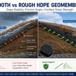
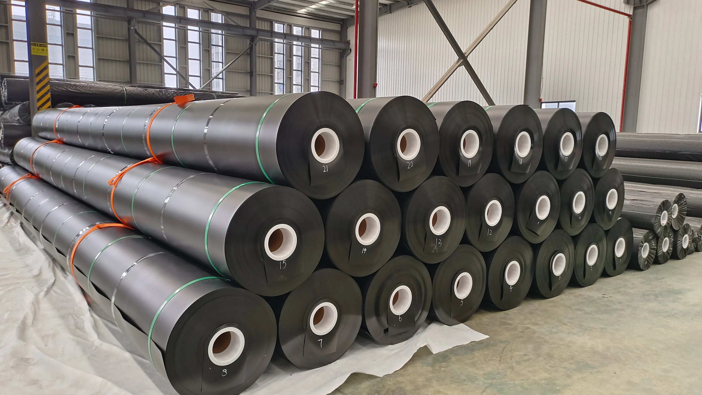
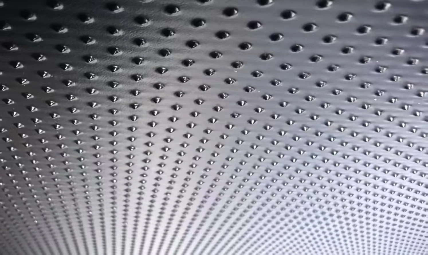
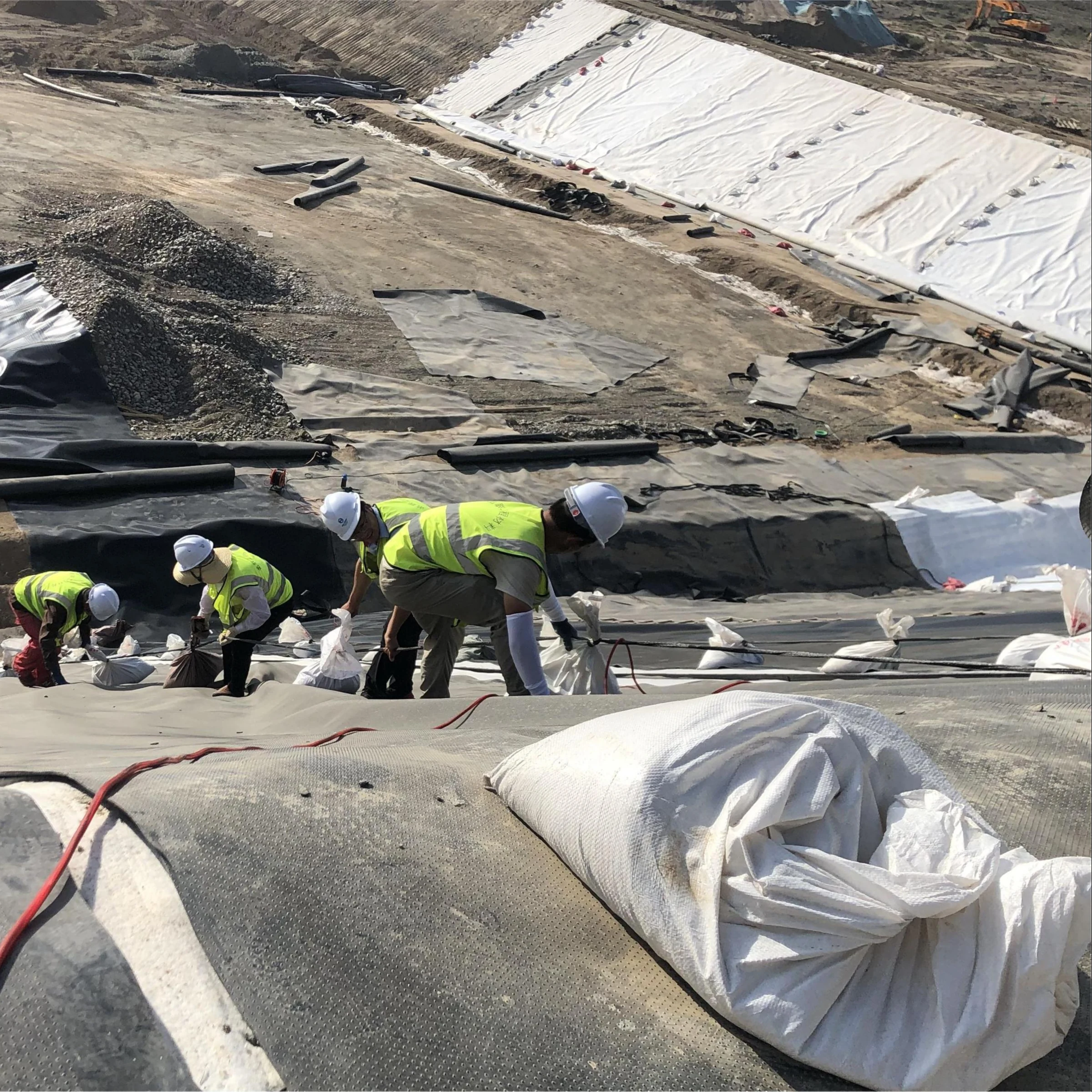

Electrical leak location (ELL) checks an installed geomembrane for electrically detectable breaches. Choose the survey method from the liner construction, cover condition and available conductive path. Conductive-backed spark testing, exposed-liner arc testing, water-puddle testing and covered-liner surveys are different methods; their settings and limitations are not interchangeable.
ELL supplements construction quality assurance (CQA) and seam testing. It does not measure seam strength, prove chemical compatibility or guarantee that no future damage will occur. Define the survey stage and acceptance requirements in the project CQA plan before installation.
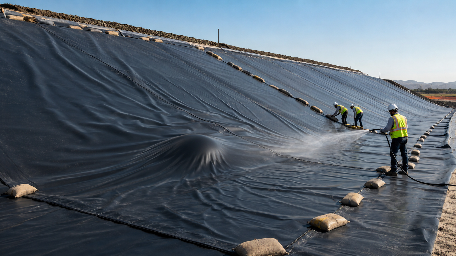
Why survey the full liner rather than only the seams?
Punctures, knife cuts and damage during placement of protective materials can occur away from welds. A seam test alone does not examine those panel areas. Exposed-liner testing before covering and a suitable survey after cover placement address different construction stages.
Alphard’s published water-puddle statistics describe 58 projects totaling 1,409,500 m², an average of 6 leaks per hectare, and 11 projects exceeding 20 leaks per hectare. These are that provider’s surveyed projects, not a random industry sample or a stated 2025 dataset. They demonstrate that defects can remain after installation; they do not predict the number of defects on another site.
For scale, 1 hectare equals 10,000 m². In a hypothetical 25,000 m² survey with 15 confirmed breaches, the reported density is 15 ÷ 2.5 = 6 leaks/ha. Record the surveyed area as well as the count: a density without its denominator can exaggerate the significance of a small repair area.
Select the ELL method from the installed system
| Method | Relevant condition | Reference and selection issue |
|---|---|---|
| Conductive-backed spark test | Exposed membrane manufactured with a conductive backing | ASTM D7240-25; verify the actual sheet construction and test arrangement |
| Arc test | Exposed insulating geomembrane with an effective electrical path beneath it | ASTM D7953-20(2024); high-voltage method, with site suitability demonstrated |
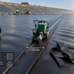
| Water-puddle test | Exposed membrane surveyed using a moving water puddle | ASTM D7002-22; water supply and the return path must be suitable |
| Covered-liner electrical survey, including dipole approaches | Membrane covered by water or earthen material | ASTM D7007-24; demonstrate detection capability for the actual cover and survey parameters |
| Seam spark test | Suitable field-seam details incorporating conductive material | ASTM D6365-26; a seam-specific test, not automatically a whole-area survey |
Do not select solely by a claimed square-metres-per-hour rate. Access, penetrations, wrinkles, cover thickness, electrical isolation, weather and the need to mark and repair defects can dominate the programme. A contractor should explain both its coverage plan and the conditions under which the proposed method would be ineffective.
Spark testing: identify which construction is being tested
“Spark testing” can mean a conductive-backed sheet survey or a test of a suitably prepared seam. Under D7240, the insulating sheet and conductive layer form the relevant manufactured system. Ordinary HDPE sheet placed over dry insulating material cannot simply be treated as conductive-backed geomembrane.
D6365 addresses appropriate seam configurations, including extrusion seams and details where conductive material can be incorporated. Check the proposed detail with the installer and testing specialist before welding. Otherwise the completed seam may not support the planned test.
Voltage, electrode geometry and travel speed must be selected and verified for the equipment, material and field conditions. A generic 15–35 kV setting, 1–10 mm probe gap or 0.5 m/s travel speed is not a universal specification. Excessive or inappropriate settings can produce misleading indications or damage. Qualified personnel should work to the approved procedure, including controls for electrical and ignition hazards.
Arc testing: high voltage, exposed membrane and a return path
Arc testing applies high voltage to identify a conductive path through a breach. It is not a low-voltage grid-mapping technique. The IGS paper comparing water-puddle and arc methods describes arc equipment operating up to 35,000 V in its discussion, contrasted with roughly 40 V for the water-puddle technique. These figures explain the methods; they are not settings to copy onto a project.
Using no surface water does not eliminate the need for a conductive return path. Dry insulating layers, air gaps under wrinkles or unsuitable subgrade contact can prevent an effective survey. The contractor must establish suitable surface conditions and demonstrate detection on the installed system.
Arc testing is intended for an exposed liner. After soil placement, select a covered-liner method rather than trying to use an exposed-surface procedure through the cover. Do not assume arc testing always scans faster than spark testing or only locates defects within a 0.5–1 m radius: those claims require evidence for the particular equipment and site.
Water-puddle and covered-water surveys are not the same
The water-puddle method systematically moves a conductive puddle across an exposed membrane. It does not require the entire basin to be flooded to a universal depth of 2–3 cm. The method description published by Alphard explains the gradual application of a thin water layer. Adequate contact, supply and electrical isolation still matter.
A basin already covered with water may instead call for a water-covered survey under D7007. Separate conditions apply to earthen cover. The cover and material beneath the liner must allow a detectable electrical path, and conductive connections around edges or penetrations can divert current.
Agree how limited-access areas, wrinkles and penetrations will be assessed. If an area cannot be surveyed under valid conditions, show it on the coverage drawing instead of reporting it as passed.
Prove sensitivity without damaging the liner casually
A universal 1 mm detection guarantee is misleading. Hole geometry, contact, cover, electrical continuity, equipment and procedure affect sensitivity. Demonstrate the required performance under representative field conditions and record the actual test conditions.
ASTM D7909-21a(2025) addresses intentional leaks used to check survey performance. Such checks require an agreed plan and the owner’s knowledge and consent. Do not puncture the installed liner with a needle as an informal daily calibration exercise. Record every intentional opening, its repair and the subsequent verification.
A successful demonstration at one location does not prove that all parts of the basin have identical contact conditions. Recheck performance when conditions or equipment change, following the approved procedure. Distinguish instrument calibration records from field demonstrations of the complete survey system.
ELL does not replace seam-strength testing
A weak but unbreached weld may not create an electrical path. ELL therefore cannot certify fusion quality or bond strength merely because no electrical anomaly was found. Use the project-specified combination of seam inspection, nondestructive testing and destructive testing.
ASTM D7747/D7747M-11(2023) concerns destructive peel and shear testing of reinforced geomembrane seams. It does not prescribe a universal 5 m ELL retest radius around a repair. For nonreinforced thermally welded sheet, D6392-25 is a relevant destructive seam-test reference. Match the method to the material and seam construction.
After a confirmed defect is repaired, record the repair identifier, location and verification result. Determine the required surrounding resurvey area from the cause of damage, construction disturbance and CQA requirements, not an invented fixed radius.
Specify a report that supports acceptance decisions
- Scope: liner system, stage of construction, surveyed area, exclusions and drawing reference.
- Method: applicable standard edition, equipment, operator qualifications and field demonstration results.
- Conditions: surface or cover condition, conductive path, isolation measures and relevant weather or access limitations.
- Findings: defect identifiers, photographs, locations and the coordinate system used. Distinguish measured opening size from an estimate.
- Closeout: repair records, retest results, unresolved limitations and the party responsible for acceptance.
Specify coordinate accuracy appropriate to the work. RTK positioning can be useful, but an automatic ±20 mm guarantee or a requirement to attach a receiver to every probe is not inherent to ELL. A well-documented local survey grid may be adequate where the contract permits it.
Agree file formats, sign-off responsibilities and submission deadlines in the contract and permit requirements. A three-party signature, a particular GIS format or a 30-day electronic filing deadline should not be described as universally required by US landfill law.
Plan cost and future monitoring around the actual risks
Request a quotation separating mobilisation, site preparation, survey coverage, repair support, resurvey and reporting. A 10-hectare site is 100,000 m², but area alone does not establish a reliable price. Covered surveys, difficult electrical isolation and multiple visits can change the scope materially. Do not compare a generic survey price with an unsupported $500,000 remediation figure as if it proved a financial return.
For operating facilities, use inspection findings, permit conditions, changes in loading and damage events to determine follow-up. Reassessment after cover placement, construction work or an incident may be more relevant than an arbitrary annual or five-year cycle. A baseline survey supports investigation, but it neither assigns legal liability nor proves that every later leak arose after construction.
For related installation planning, see our geomembrane overlap and quantity guide and anchor-trench design considerations. Confirm the liner cross-section and inspection sequence with the project designer and qualified ELL contractor before procurement.