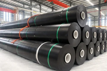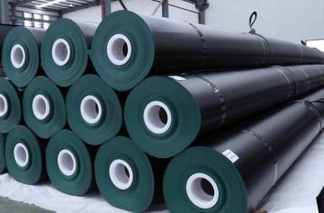

Calculate geomembrane quantity from the actual lined surface, the approved panel layout, seam overlaps, anchor returns and cutting allowances. Plan-view pond area alone is insufficient where slopes and termination details add surface area. An overlap is also not the same as the fused width of a weld.
This guide separates those quantities and provides worked examples. Example overlap widths and allowances are estimating assumptions, not universal installation requirements. Confirm the seam detail and welding procedure before placing a material order.
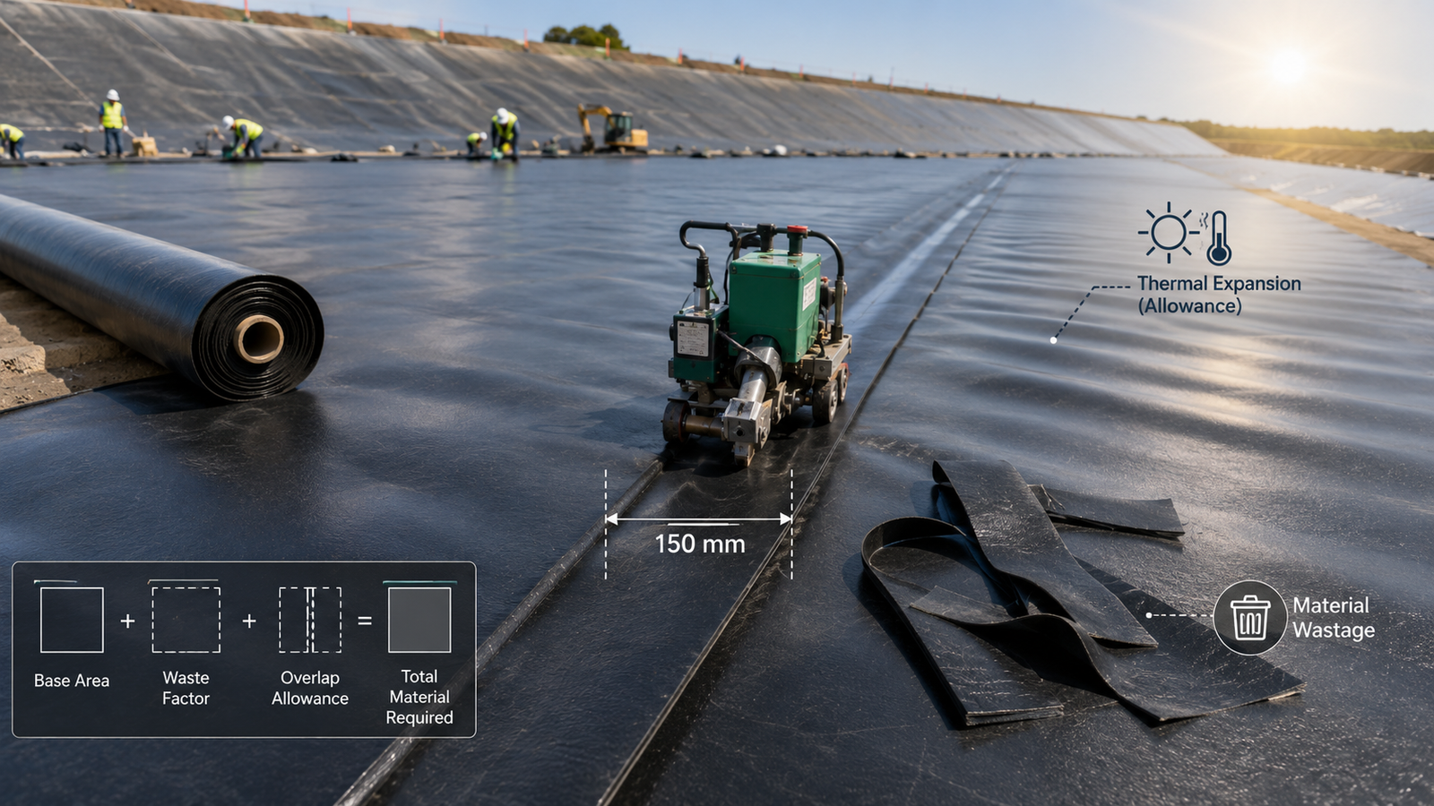
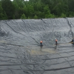
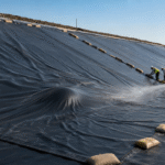
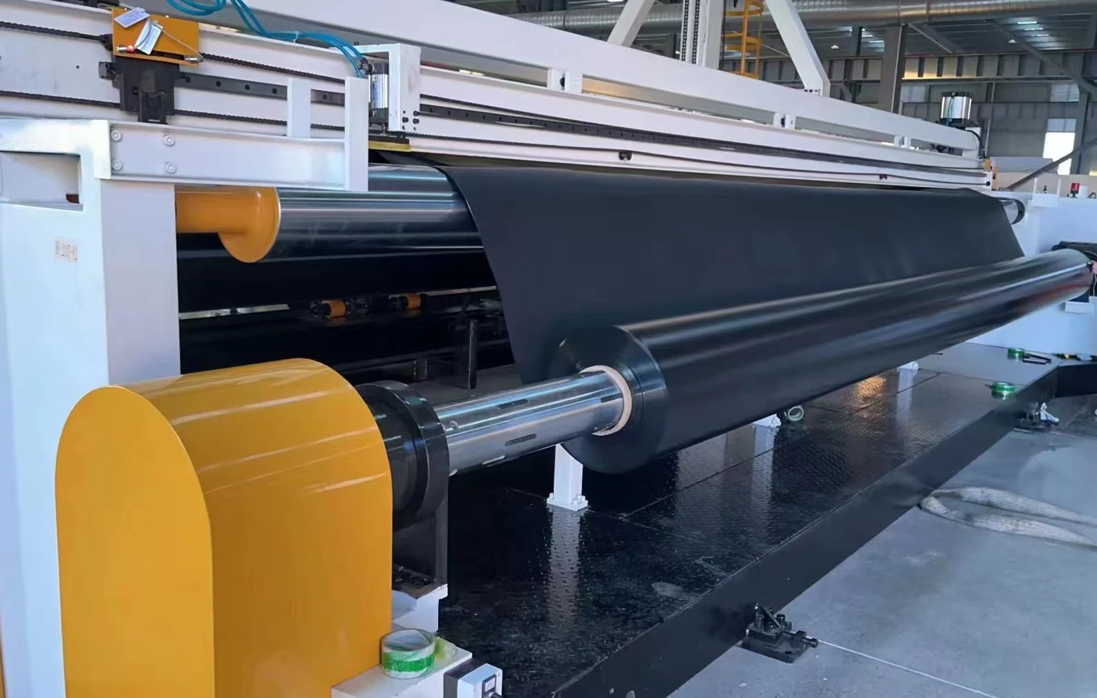
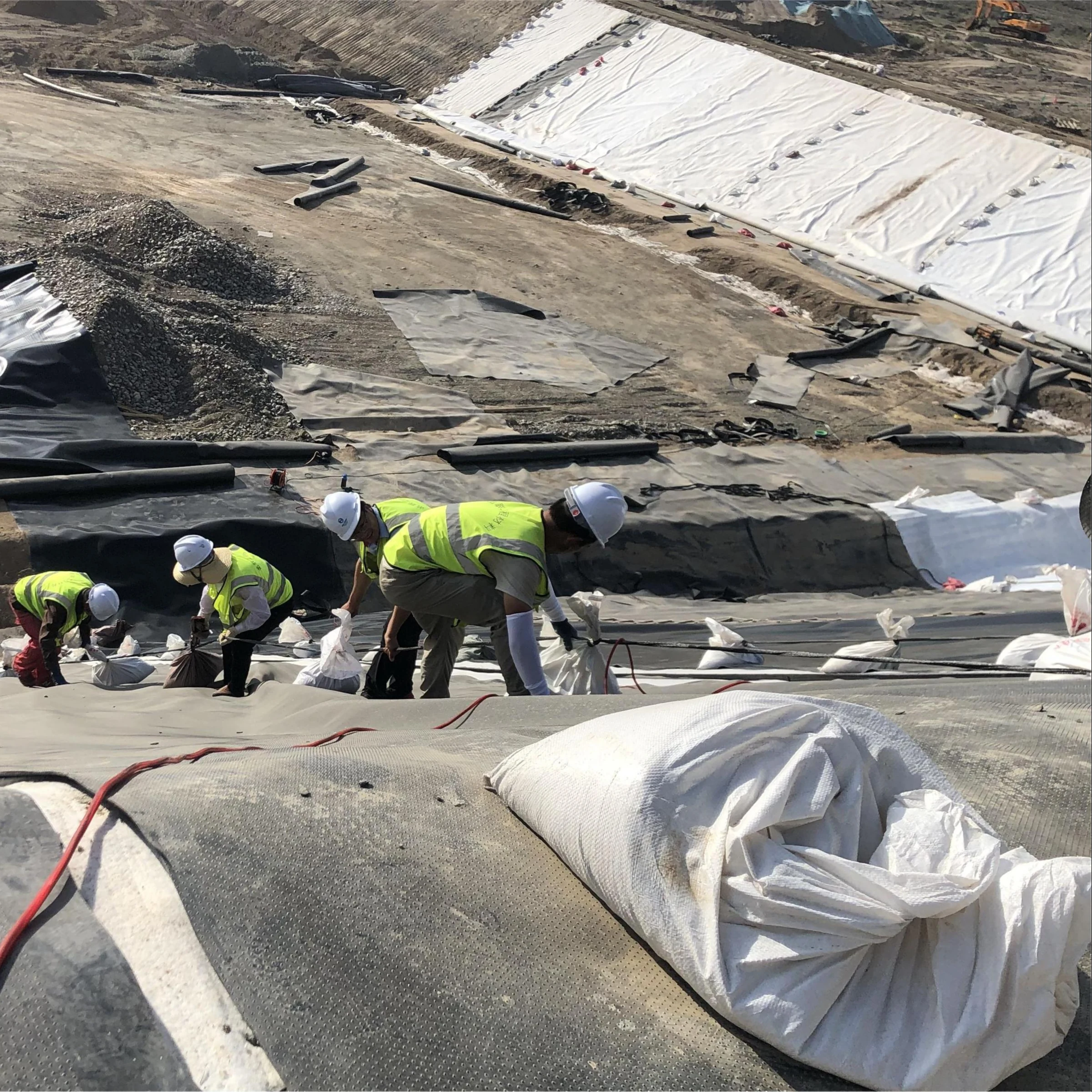
Installation illustration only: the 150 mm overlap is an example, not a universal requirement. Apply the waste factor to an area before adding it to the takeoff; follow the approved seam and installation details.
Overlap width versus weld width
Overlap width is the distance one sheet extends across the adjacent sheet. Weld width is the bonded portion created by the qualified seaming process. A dual-track weld also has an air channel between its bonded tracks. Sheet alignment, equipment geometry, preparation and testing access affect the overlap required.
Increasing unused overlap does not automatically increase the bonded width or seam strength. Conversely, an overlap that leaves insufficient room for the approved weld or testing detail is unacceptable even if the total purchased area is correct.
Use the liner manufacturer’s instructions, installer procedure, approved drawings and project specification to establish the required overlap and tolerances. Do not treat 100, 150 or 200 mm as mandatory worldwide values for every polymer, thickness and welding method.
Choose the correct seam standard
ASTM D6392-25 evaluates nonreinforced geomembrane thermo-fusion seams through destructive testing. It is not a universal purchasing formula for overlap area. The applicable material and project specifications establish the required acceptance criteria and sampling plan.
ASTM D7056-26 addresses bituminous geomembrane seams; it should not be cited as the HDPE seam test. ASTM D7700-22 helps select suitable seam evaluation methods for different materials. Continuity tests and destructive strength tests answer different questions, so passing one does not automatically establish the other.
List the chosen welding process, trial-weld requirements, inspection coverage, destructive sampling, acceptance criteria, repair procedure and records in the installation plan. The seam test method, pressure and duration must suit the actual seam and approved specification. Avoid applying an air-channel pressure or spark-test setting to every liner thickness and construction.
Measure the actual area, including slopes
A sloping face is larger than its horizontal projection. For a straight face with vertical height h and horizontal run r, its slope length is √(h² + r²). If h = 3 m and r = 6 m, the slope length is about 6.708 m, not 6 m.
For a rectangular slope strip that is 50 m long with that constant cross-section, its actual surface area is approximately 335.4 m². The plan-view projection is only 300 m²: a difference of 35.4 m² before adding seams or terminations. Real pond corners may be trapezoidal or more complex, so use surveyed geometry or a surface model rather than applying this strip formula indiscriminately.
Include the bottom, every slope, benches and other lined faces. Measure anchor returns and terminations from their developed sheet dimensions. Check whether these are already included in the surface takeoff before adding them again.
Calculate the overlap area from a panel layout
For constant-width overlaps, an initial estimate is:
Aoverlap = Σ(oi × Li)
Here o is the overlap width in metres and L is the corresponding seam length in metres. Count each seam once. At seam intersections, patches and irregular details, use the actual panel geometry to avoid double-counting or missing material.
For parallel full-length strips, the covered width from n panels is nW − (n − 1)o, where W is roll width and o is side overlap. The minimum number of strips across width B is therefore the rounded-up value of (B − o)/(W − o), provided W is greater than o.
| Example input or result | Value |
|---|---|
| Rectangular area to cover | 20 m × 50 m = 1,000 m² |
| Assumed panel width and length | 7 m × 50 m |
| Assumed side overlap | 0.15 m |
| Panels across the width | ceil((20 − 0.15)/(7 − 0.15)) = 3 |
| Full-panel area | 3 × 7 × 50 = 1,050 m² |
| Side overlap area | 2 × 0.15 × 50 = 15 m² |
| Remaining outer-width allowance | (20.7 − 20) × 50 = 35 m² |
This example has no end overlaps, slopes, anchor returns or penetrations. It demonstrates why simply adding a percentage to the net area is less precise than laying out actual panels.
Worked procurement estimate: 3,200 m² lined surface
Assume that 3,200 m² is the actual developed area, rather than a horizontal projection. For this example only, assume a separate 12% allowance for cutting and minor details that excludes seam overlaps, a seam length of 480 m and an approved estimating overlap of 150 mm.
| Item | Calculation | Area |
|---|---|---|
| Actual lined surface | Measured takeoff | 3,200 m² |
| Assumed non-overlap allowance | 3,200 × 12% | 384 m² |
| Overlap area | 480 × 0.15 | 72 m² |
| Subtotal | 3,200 + 384 + 72 | 3,656 m² |
| Optional separate contingency | 3,656 × 5% | 182.8 m² |
| Illustrative estimate | 3,656 + 182.8 | 3,838.8 m², rounded to 3,839 m² |
The arithmetic is valid, but 12% and 5% are assumed allowances, not industry requirements. Do not add a second contingency if the first allowance already covers the same uncertainty. Explicitly add any anchor, repair or detail quantities not included in those assumptions.
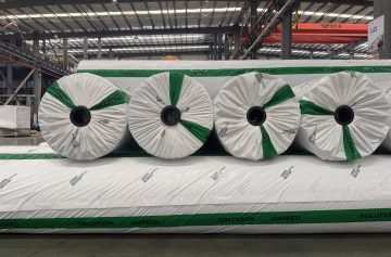
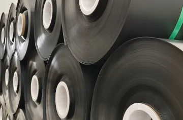
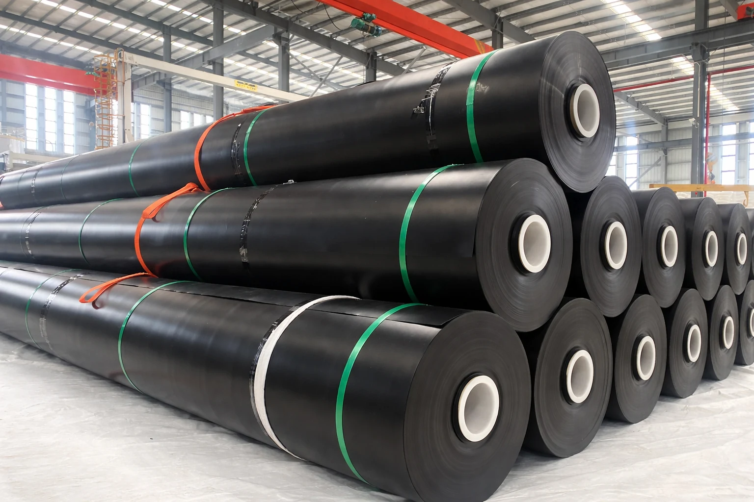
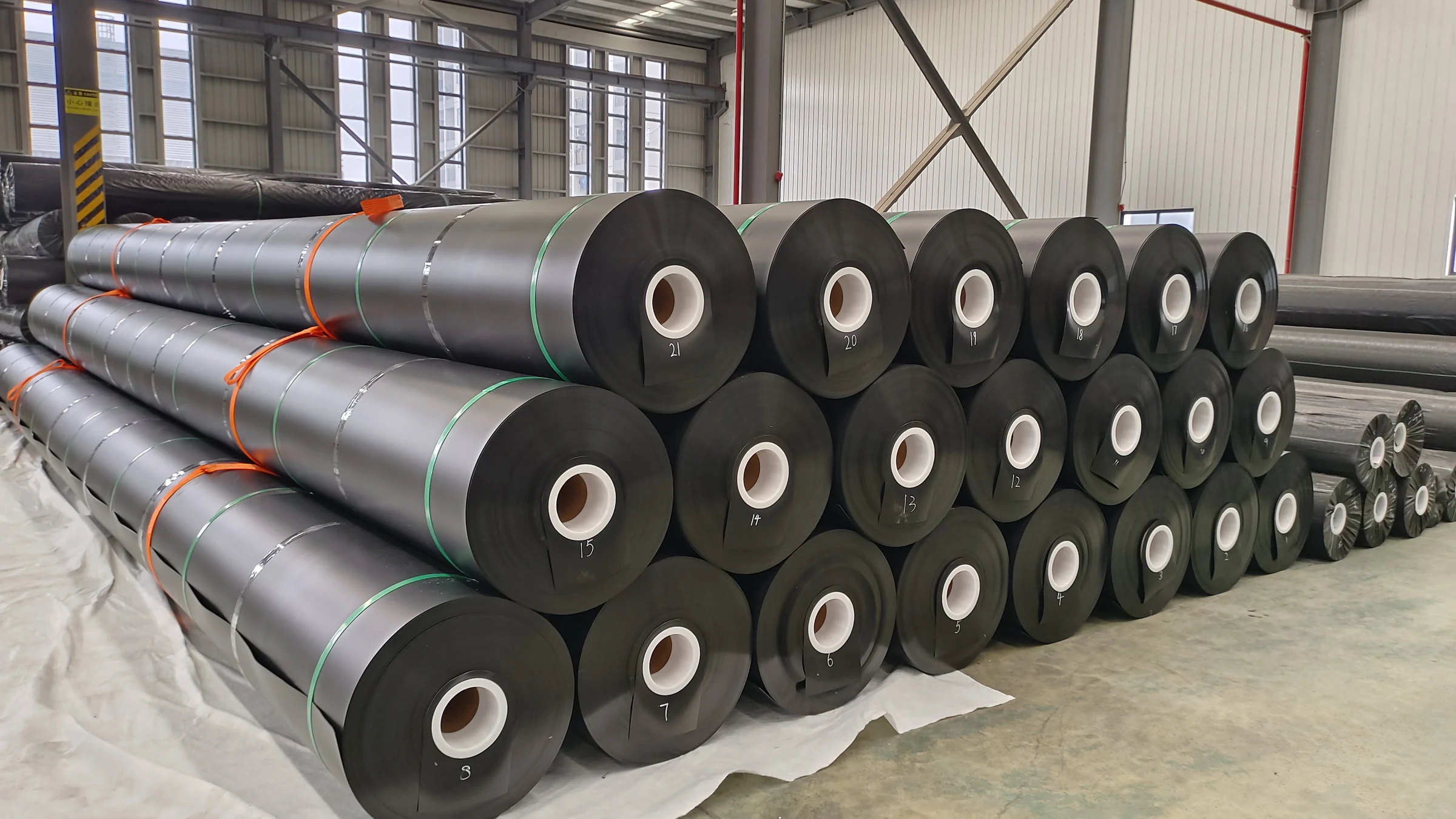
Purchasing must then respect available roll sizes and the cutting plan. If full rolls were 7 m × 100 m, the area-only minimum would be six rolls, or 4,200 m². That is not proof six rolls can satisfy every panel shape or installation sequence; verify the actual nesting layout and usable offcuts.
Reduce wastage without compromising seams
- Compare alternative roll widths against the surveyed geometry, permitted seam orientation and handling constraints.
- Separate unavoidable overlaps from trim losses, anchor returns, patches and spare material in the takeoff.
- Mark each panel and seam on the layout, including end joints and penetration details.
- Record reusable offcuts by material, thickness, dimensions and condition; do not assume all trim is suitable for a structural patch.
- Reconcile installed panels, unused rolls and actual scrap so the estimate can be checked against construction records.
A narrower roll can fit an irregular site more efficiently, but it can also add seams. A wider roll can reduce seam length while creating more unusable trim. Compare total supplied and installed cost from the actual layout, not a claimed universal saving percentage.
Thermal movement: retain the calculation, qualify the allowance
The free linear thermal movement estimate is ΔL = αLΔT. If an illustrative coefficient α = 120 × 10−6/°C, a 100 m length and a 25°C temperature increase are assumed, free expansion is 0.30 m. Use the selected product’s data and relevant membrane temperatures for a project calculation; black sheet temperature can differ from air temperature.
This is free movement, not a directly specified slack length or a seam overlap. Actual movement depends on restraint, friction, geometry and material behavior. A thermal force cannot be calculated from temperature change and length alone: cross-section, stiffness, restraint and time-dependent response also matter.
Warming can generate expansion and wrinkles, while cooling a restrained liner can increase tension. Do not intentionally form prescribed waves or fix a universal sandbag spacing on the basis of this calculation. Coordinate deployment, temporary restraint, trial welding and covering with the qualified installation procedure and observed sheet condition.
A fixed 4–8 a.m. installation window is not suitable for every climate or project. Weather, condensation, wind, surface temperature and demonstrated weld quality should guide the work. Unverified claims that HDPE becomes brittle at 0°C or that one ASTM guide universally doubles cold-weather sampling should not be used as acceptance rules.
Before releasing the material order
Confirm the actual surface takeoff, panel layout, approved seam and anchor details, roll dimensions and distinct allowances. Then verify the material grade and installation requirements together. For related design inputs, see geomembrane anchor-trench considerations and the HDPE geomembrane product page. The final quantity should be traceable to a drawing and calculation, not just a generic waste factor.