HDPE geomembrane has a linear expansion coefficient of approximately 1.2 x 10⁻⁴ per degree C, meaning each meter of liner expands or contracts 0.12mm for every degree C change. An 8m-wide, 100m-long HDPE sheet in a 30 degree C temperature swing will change length by approximately 288mm – roughly the width of three adult fists. This thermal expansion and contraction is the primary driver of wrinkles and bulges. Without proper control, installed geomembrane can develop air voids and bulges under solar heating or suffer joint seam tears from excessive contraction in cold conditions. This article, based on GRI-GM13 and GRI Technical Note, outlines practical control measures across three dimensions: high temperature, void prevention, and ballast systems.
Thermal Expansion and Contraction
High Temperature and Wave Patterns
HDPE has a linear expansion coefficient of approximately 1.2 x 10⁻⁴ per degree C, meaning each meter of liner changes length by 0.12mm per degree C. In summer landfill conditions, membrane surface temperatures can reach 60 degrees C, while nighttime or winter temperatures may drop to 0 degrees C – a 60 degree C differential that causes a 100m-long sheet to contract by approximately 720mm. This large contraction, if not accounted for during installation with proper slack allowance, will directly tear seam joints or rupture the membrane body itself. GRI Technical Note recommends providing 1 to 2mm of thermal expansion slack per meter of liner length, with the specific value determined by the local historical maximum temperature differential.
I experienced a membrane wrinkle scare during a summer installation: at 2pm, with surface temperatures exceeding 55 degrees C, a 3mm HDPE sheet on a slope suddenly developed 5 to 8cm-high wave-shaped wrinkles with enough clearance underneath to walk bent over. After rushing 2 tonnes of sandbags to weight down the wrinkle crests, the membrane gradually returned to flat as temperature dropped. That incident taught me a lasting lesson: no one should walk on slopes during high-temperature hours – every step stretches the membrane and worsens wrinkle development.
Wave-pattern wrinkles form because the center of the membrane expands more than the edges when heated, creating alternating peaks and valleys in a buckling pattern. Field surveys at three European landfills (2021-2023) found wrinkle heights ranging from 3cm to 12cm during summer peak temperatures, with the worst cases on south-facing slopes exposed to direct solar radiation for more than 6 hours per day. At wrinkle peaks, the membrane is elevated and unsupported, creating abrasion risk and large-amplitude oscillation under wind loading that accelerates fatigue damage. Each wrinkle peak undergoes 50 to 200 oscillation cycles per day under moderate wind conditions, and HDPE fatigue life at these cyclic loads can be exhausted within one to two seasons if wrinkles are not re-flattened. If wrinkles have formed and cannot be eliminated, they must be re-flattened only when air temperature drops below 25 degrees C – never attempt to forcibly pull wrinkles flat during high-temperature conditions.
Cooling Methods
Controlling membrane surface temperature is the most direct method of preventing high-temperature wrinkles. The standard practice is spraying water mist on the membrane surface, using water’s latent heat of vaporization (2,260 kJ/kg) to remove heat and reduce surface temperature by 5 to 15 degrees C. Spraying should be done during high-temperature windows – before 10am or after 3pm – at a rate of approximately 0.5 to 1L per square meter. Finer mist droplets provide more uniform cooling. Critical note: standing water must not be allowed to seep into seam weld areas, as moisture reduces weld strength – install temporary water barriers along both sides of seam zones (500mm range) before spraying.
Another method is covering the membrane with temporary shade cloth, maintaining a 10 to 20cm air gap between the cloth and membrane surface to create a thermal insulation layer. This can reduce membrane surface temperature by 10 to 20 degrees C compared to direct solar exposure. A petrochemical tank farm project measured actual surface temperature reduction from 62 degrees C to 45 degrees C after shade cloth installation – a 17-degree C drop that significantly improved seam welding quality. When shade cloth is unavailable, unroll the membrane and allow it to rest for 2 to 4 hours before installation, letting the sheet temperature equilibrate with ground temperature and reducing subsequent thermal variation amplitude.
Droplet size in mist cooling significantly affects performance. Droplets smaller than 0.1mm evaporate almost instantly upon contact with the hot membrane surface, providing immediate but short-duration cooling. Droplets larger than 0.5mm tend to run off before fully evaporating, wasting water and potentially pooling at seams. The optimal droplet size range is 0.2 to 0.4mm. Professional misting systems produce droplets in this range and cost approximately $200 to $500 per day to rent for large-area projects. In extreme high-temperature environments, a third option is specialized geomembrane cooling agent spray – a modified silane compound that forms a transparent thermal-dissipation coating, achieving 30 to 40 percent greater cooling than plain water at approximately $1.20 per square meter.
Optimal Installation Timing
The optimal geomembrane installation temperature window is 10 to 25 degrees C, when the liner material is pliable without being tacky, easy to flatten, and experiences minimal thermal expansion or contraction. One to two hours after sunrise (approximately 8 to 10am), the ground has absorbed some heat but not yet built to peak temperatures – this is generally the best installation window. Late afternoon after 4pm is also suitable, but installers must watch the night’s cooling rate: if temperature is forecast to drop more than 15 degrees C within 3 hours after installation, contraction stress may exceed the reserved slack allowance.
In Nordic and Canadian high-latitude regions, spring and fall seasons with average daily temperatures of 10 to 18 degrees C are considered the gold standard installation period, typically from 9am to 3pm. In Middle East or Southeast Asian tropical regions, the 11am to 3pm high-temperature window must be strictly avoided, and installation rescheduled to 6 to 9am or 4 to 7pm, or even night-shift installation may be necessary. Regardless of climate zone, review historical extreme temperature records for the project site before installation to establish the baseline for slack allowance calculation. The thermal expansion slack formula is: slack (mm) = liner length (m) x temperature differential (degrees C) x 0.12mm/m/degrees C x safety factor (typically 1.1).
For 24-hour project operations, the critical window to avoid is 11am to 3pm solar peak. If night installation is required, provide adequate artificial lighting – membrane surface defects are harder to detect under poor lighting, and seam welding quality directly suffers. Minimum lighting requirement is 500 lux at the membrane surface during night welding operations. Additionally, night installation requires extra attention to morning condensation: if membrane is installed shortly before dawn, the subsequent temperature rise will find the membrane in a contracted state, potentially creating stress in newly completed seams. Build at least a 4-hour buffer between installation completion and expected solar heating.
Void Prevention
Edge Looseness Repair
Geomembrane edges are the most vulnerable areas to loosening – insufficient overlap width during installation, wind uplift, or subgrade irregularities can all create voids that become leak pathways. The standard repair method for edge looseness is to cut out the loose section, re-install with proper overlap width of at least 150mm for hot wedge welding or at least 200mm for extrusion welding, then perform peel strength testing on the repaired seam zone. For large loose areas, removable metal clamps can provide temporary fixation until formal welding is possible.
A landfill project experienced an edge blow-off incident: overnight gusts exceeded 70km/h, lifting more than 2 square meters of unballasted slope membrane. The next morning inspection revealed torn seams in the overlap zone. The lesson: any installed membrane that has not yet received permanent ballast must have someone on watch or receive temporary sandbag anchoring if night winds are forecast to exceed 50km/h. Membrane edges are always at risk until permanent ballast is in place. After repair, samples should be taken from the tear locations and sent to a laboratory for tensile strength testing to confirm that the surrounding membrane body has not suffered latent damage.
Permanent repair welds on damaged edges should use the same or higher specification welding parameters as the original installation. Before welding, the membrane surface within 50mm of the repair zone must be cleaned with isopropyl alcohol (IPA) to remove surface contamination that could compromise weld strength. After welding, allow the repair seam to cool for at least 30 minutes before applying any stress – a common mistake is to immediately re-ballast the repair zone, which can cause micro-distortion in the still-cooling weld bead, creating a stress concentration point that may fail within weeks. Avoid aluminium clamps in wet or chemically active environments – use nylon or stainless steel clamps instead, with width at least 100mm and evenly distributed clamping pressure.
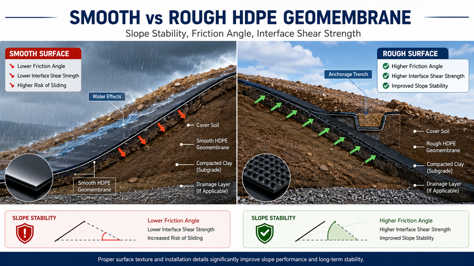
Slope Tensile Risk
When geomembrane is installed on a slope, the gravitational component acts along the slope direction, stretching the membrane. The steeper the slope, the more pronounced this tensile effect. On slopes exceeding 30 degrees, if the membrane surface is not adequately secured, combined self-weight and wind loading will cause downward creep that eventually produces microcracks in seam overlap zones, leading to leaks. For slopes steeper than 20 degrees, an anchor trench must be used to fix the membrane crest. Anchor trench depth is typically at least 300mm and width at least 200mm, with backfill compacted in layers.
Slopes of 20 degrees or less can use grid-pattern ballast instead of full-length anchorage. Ballast spacing is calculated based on slope angle and wind pressure: for 10 to 20 degree slopes, use 1.5m by 1.5m grid spacing; for 5 to 10 degree slopes, 2m by 2m spacing is sufficient. On slopes with rock or gravel protection, ballast points must avoid sharp rock edges – install geotextile protection layers between rocks and membrane where needed to prevent puncture. Additionally, the top of sloped membranes should reserve 20 to 30 percent more liner length than flat areas, to compensate for slope curvature and wrinkle slack, preventing tensile failure from insufficient allowance during high-temperature expansion.
For slopes exceeding 25 degrees, installing transverse ballast strips (sand collars) every 5m across the membrane width is recommended. These strips are 300 to 500mm wide, made from the same specification material as the main liner, and heat-fused into the membrane as an integral unit to further distribute the gravitational component. For aging slope membranes showing existing creep, conduct a dedicated assessment: measure current seam overlap tensile strain. If strain exceeds the material allowable limit (typically 12 to 15 percent for HDPE), develop a replacement or reinforcement plan rather than simply adding more ballast weight. Tensile strain in sloped geomembrane can be monitored using photogrammetry – a series of calibrated photographs taken from fixed positions can measure membrane surface displacement to an accuracy of approximately 1mm. If cumulative displacement exceeds 20mm at any marker, investigate whether anchor or ballast systems have degraded.
Subgrade Preparation
Subgrade flatness directly determines whether voids will form in the installed membrane. Standards require subgrade flatness deviation of no more than 20mm per 2m – meaning a 2m straightedge should have gaps no larger than 20mm when placed on the surface. For sand subgrades, compact to flatness first, with moisture content controlled at 8 to 12 percent. Over-wet sand, when compacted, produces a springing effect that leads to uneven settlement and creates membrane surface bulges. When geomembrane is installed directly over an uneven subgrade, locally suspended areas form air voids under the membrane that expand and contract with membrane surface pressure changes, eventually tearing the membrane or displacing it.
In practice, I require subgrade acceptance in three sequential steps: Step one, visual inspection to remove sharp stones, roots, and construction debris. Step two, 2m straightedge and feeler gauge flatness test, with one measurement point per 100 square meters. Step three, bearing capacity test (CBR at least 3 percent) to confirm subgrade compaction. All three steps must pass before geomembrane installation begins. One project I supervised failed step two – subgrade flatness deviation reached 35mm. After three additional compaction passes, the subgrade finally passed, taking two extra days. But that delay avoided much larger costs from post-installation rework.
In addition to flatness, subgrade soil classification matters for long-term performance. Expansive clay soils (with plasticity index above 15) can swell and shrink with moisture changes, creating differential settlement that stresses the geomembrane. If expansive clay is present, a 150mm layer of granular material (sand or gravel) should be placed over the clay before geomembrane installation, providing both a stable working surface and a moisture buffer. In freezing climates, the subgrade must be protected from frost heave – the freeze-thaw cycle in saturated subgrade soils can cause upheaval forces exceeding 50kPa, sufficient to damage or displace improperly designed geomembrane systems. Frost depth surveys should be conducted during site investigation in climates with ground frost risk.
Ballast Systems
Sandbag Placement
Sandbags are the most commonly used geomembrane temporary ballast device. Standard sandbag dimensions are approximately 600mm by 400mm by 150mm, weighing 15 to 25kg when filled. Spacing depends on wind pressure and slope: on flat ground with no wind, a 3m by 3m grid is acceptable, covering approximately 9 square meters per bag. Under moderate wind (30 to 50km/h), tighten to 2m by 2m. Under high wind or on slopes, further tighten to 1.5m by 1.5m, covering only 2.25 square meters per bag.
Bag placement position matters: place sandbags over membrane valleys or seam overlaps, not over high points, so they anchor the membrane without creating new stress concentrations. Each seam overlap should have a sandbag within 500mm on both sides, creating a clamping effect that prevents wind from lifting the seam zone. Place a geotextile cushion layer between sandbags and membrane to prevent direct sand abrasion. Geotextile cushion costs approximately $0.50 per square meter – minimal insurance compared to membrane replacement costs of $5 to $15 per square meter if abrasion damage occurs.
Sandbag seam stitching is the weakest point: under strong wind, a broken stitch allows sand to leak out and ballast effectiveness fails instantly. Choose double-stitched or heat-sealed sandbags with seam strength of at least 200N per 50mm. The weight of a water-saturated sandbag can be 40 to 60 percent greater than its dry weight – a bag rated at 20kg dry may weigh 28 to 32kg when fully saturated. Account for saturation weight gain when calculating ballast requirements in humid or rainy climates. On slopes, use a pyramid stacking method: 3 bags at the base, 2 in the middle, 1 on top – this provides more than 40 percent greater wind uplift resistance than single-layer flat placement. Use geotextile bags instead of woven polypropylene when prolonged UV exposure is expected, as PP woven bags degrade significantly under UV with tensile strength loss of 30 to 50 percent after one summer season.
Wind-Resistant Fixing Methods
For coastal or mountain-pass projects with strong winds, standard sandbags may be insufficient, requiring an enhanced wind-resistant fixing system. Geomembrane-specific earth anchors with steel cable networks are the common solution: each anchor provides 500 to 1,500kg pull-out resistance, with spacing calculated based on design wind pressure, typically no more than 3m by 3m. Steel cables run in both directions to create a grid restraint system.
Another option is water-filled ballast bags, each holding 200 to 2,000L of water with a resulting weight exceeding 200kg, and with a soft flexible body that conforms to the membrane surface without abrasion. In a Middle East tailings dam project where wind speeds routinely exceeded 80km/h, the designer specified a combined water-bag-plus-anchor system that withstood 3 years of multiple severe wind events without a single blow-off incident. This combined system saves approximately 30 percent in labor costs compared to a sandbag-only approach. The limitation of water bags is that they freeze below 0 degrees C and must be drained and stored indoors before winter arrives.
Earth anchor selection depends on soil conditions: sandy soil calls for screw anchors where installation torque directly indicates pull-out resistance; clay soil requires wedge anchors with pre-drilled holes. On-site pull-out testing is mandatory before full deployment – randomly test 3 to 5 percent of anchors with a dynamometer to verify actual pull-out force reaches at least 100 percent of design value. Non-compliant anchors must be re-installed or relocated. A 200mm by 200mm HDPE pad must be placed between each anchor head and membrane to distribute concentrated stress and prevent the anchor cap from puncturing the membrane. For permanent installations, use 304-grade or higher stainless steel cables with HDPE outer jacketing to prevent direct cable-to-membrane friction.
Wind load calculations for these extreme conditions should reference ASCE 7 provisions for membrane roof systems, which provide more conservative design inputs than standard geomembrane wind load guidance.
Weight Inspection Techniques
Regardless of ballast type, regular weight inspection is the key to preventing silent ballast failure. Sandbags gain 30 to 50 percent weight when soaked by rain and lose weight from long sun exposure as moisture evaporates – a bag initially weighing 25kg can fluctuate by plus or minus 5kg within one month. Inspect using a portable platform scale, bag by bag. Bags below 75 percent of their designed weight must be immediately replaced or topped up.
Water-filled bags require leak inspection: each minor leak can lose 2 to 5L per day, and if not replenished in time, ballast effectiveness gradually degrades. Mark each water bag with an initial fill line and check actual water level weekly. If the level has dropped more than 5cm below the initial line, top up immediately. Anchor and cable systems require inspection for looseness or corrosion – the stainless steel anchors specified for use with HDPE geomembrane have a service life of approximately 15 to 20 years. If anchor caps show visible rust spots, replace them promptly. All inspection results must be recorded in the construction log as part of the project acceptance documentation.
For a typical 10-hectare landfill, geomembrane installation costs range from $80,000 to $120,000, while rework costs from wrinkle-related defects typically run $5,000 to $15,000. Proper ballast system design and regular inspection represent the lowest-investment, highest-return engineering quality assurance available for geomembrane installations. Investing adequate resources in subgrade preparation, temperature management, and ballast monitoring during installation prevents costly remediation and ensures long-term environmental containment integrity.
| Ballast Type | Application Scenario | Coverage per Unit | Advantages | Disadvantages |
|---|---|---|---|---|
| Sandbag (15-25kg) | Flat ground, low to moderate wind | 2.25-9 m2 (spacing 1.5-3m) | Low cost, reusable | Weight fluctuation, requires regular check |
| Water-filled bag (200-2000L) | High wind, slopes, temporary | 3-12 m2 | Heavy, no abrasion, fast install | Requires water top-up, freezing risk |
| Earth anchor + steel cable | Permanent, high-wind zones | Per design spacing (typically 3m max) | High pull-out strength, permanent | High upfront cost, professional install required |
| Sand-filled berm | Long-term landfill cover, slope toe | Continuous linear | Excellent wind resistance, monolithic | Requires large sand volume, high handling cost |
Per GRI Technical Note, HDPE geomembrane has a linear expansion coefficient of approximately 1.2 x 10⁻⁴ per degree C, meaning each meter changes length by 0.12mm per degree C. A 60-degree C differential – common between summer and winter in temperate regions – causes a 100m-long sheet to expand or contract by approximately 720mm. Without sufficient slack allowance during installation, thermal movement can directly tear seam joints.
For slopes exceeding 30 degrees, GRI-GM13 recommends anchor trenches for membrane crest fixation, with trench depth at least 300mm and width at least 200mm, backfilled and compacted in layers. Without anchor trenches, sloped geomembrane under combined self-weight and wind loading develops downward creep that produces microcracks in seam overlap zones and subsequent leaks.
Field measurements at a petrochemical tank farm showed that shade cloth installation (with 15cm gap to membrane) reduced membrane surface temperature from 62 degrees C to 45 degrees C in summer afternoon conditions – a 17-degree C reduction. Shade cloth costs approximately $0.80 per square meter and represents a one-time investment usable across multiple construction cycles, delivering significant cost-benefit for high-temperature projects.
The combined water-bag-plus-anchor system was validated over 3 years at a Middle East tailings dam project subject to wind speeds exceeding 80km/h. Compared to sandbag-only systems, the combined approach saved approximately 30 percent in labor costs and recorded zero blow-off incidents. Data source: project technical report.
For extremely high-wind environments exceeding 120km/h, engineering consultation is recommended to perform project-specific wind load calculations before finalizing the anchor grid spacing.