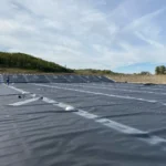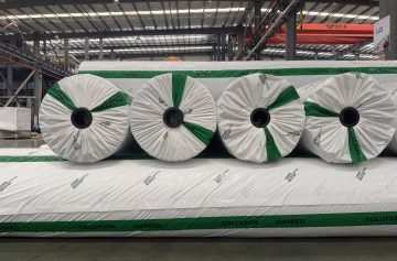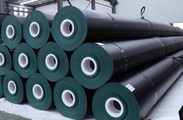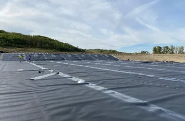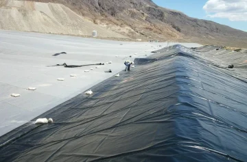
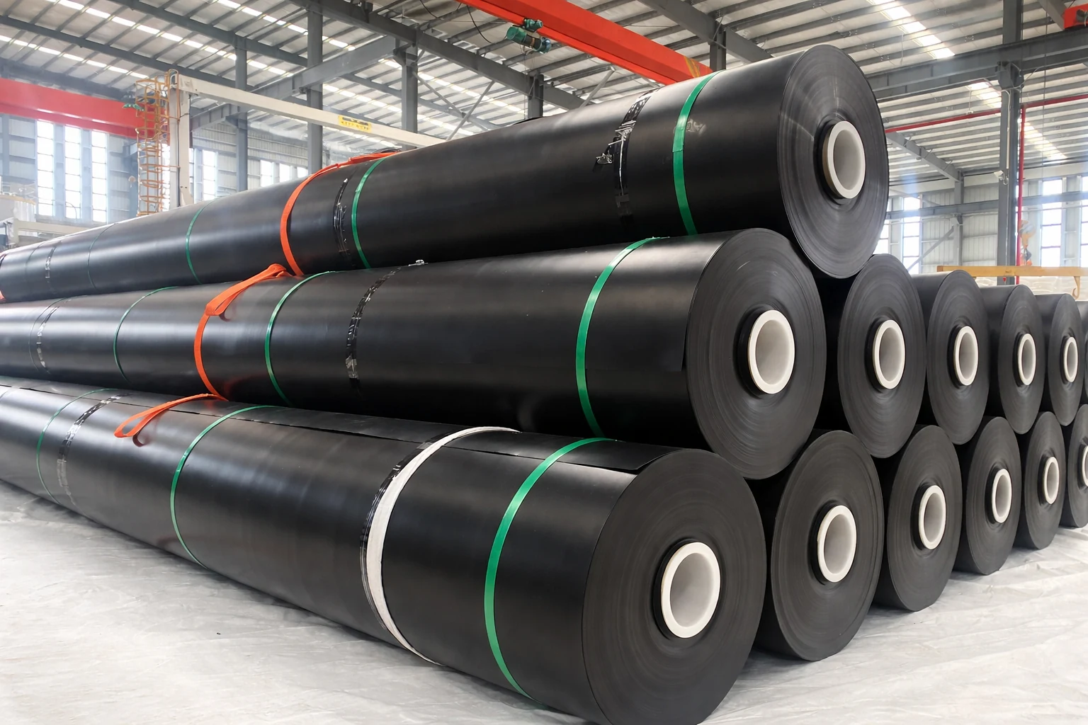
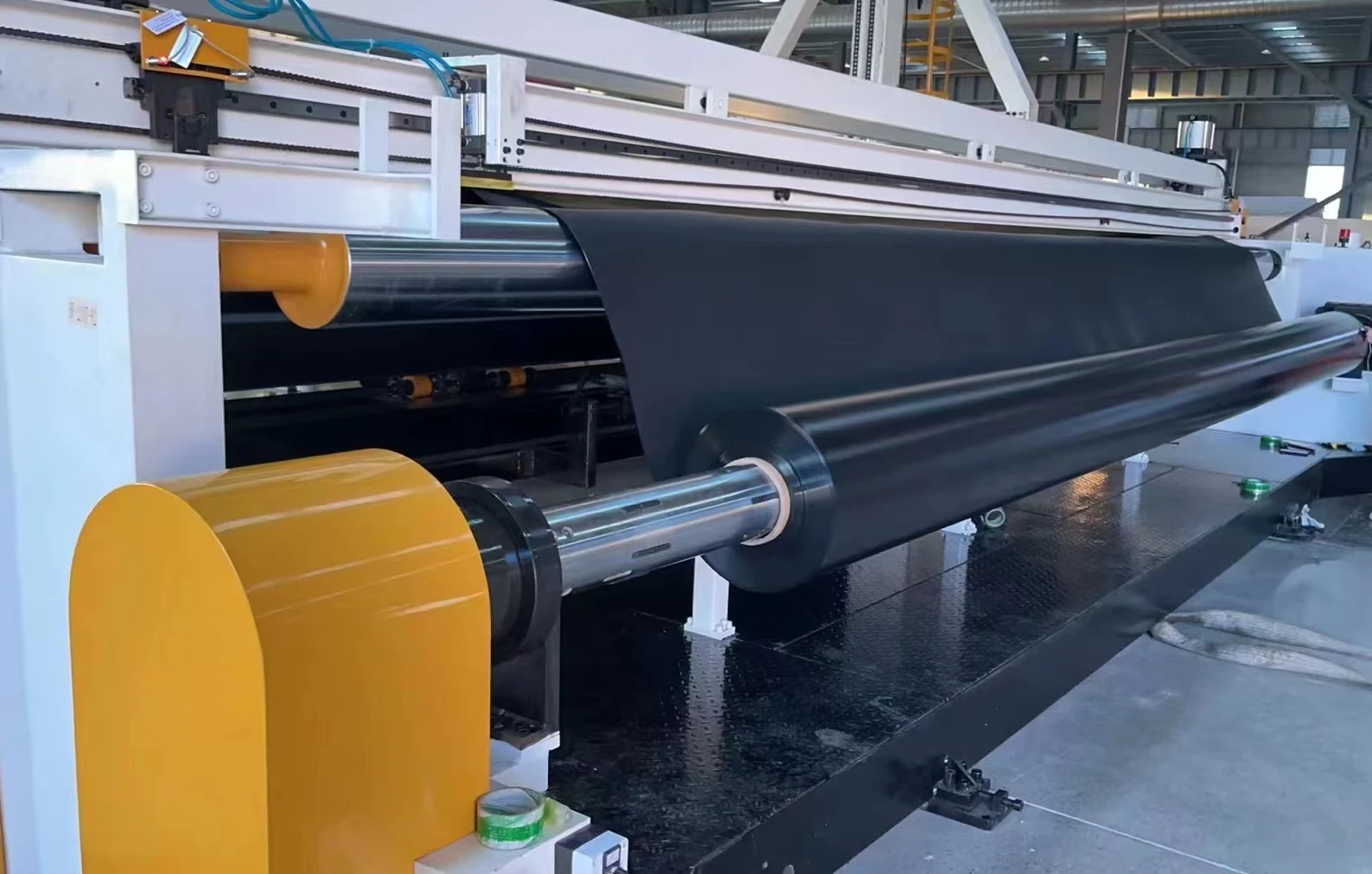
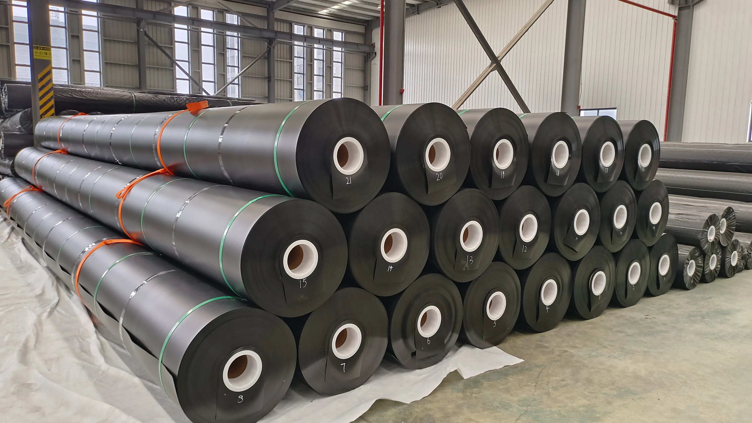
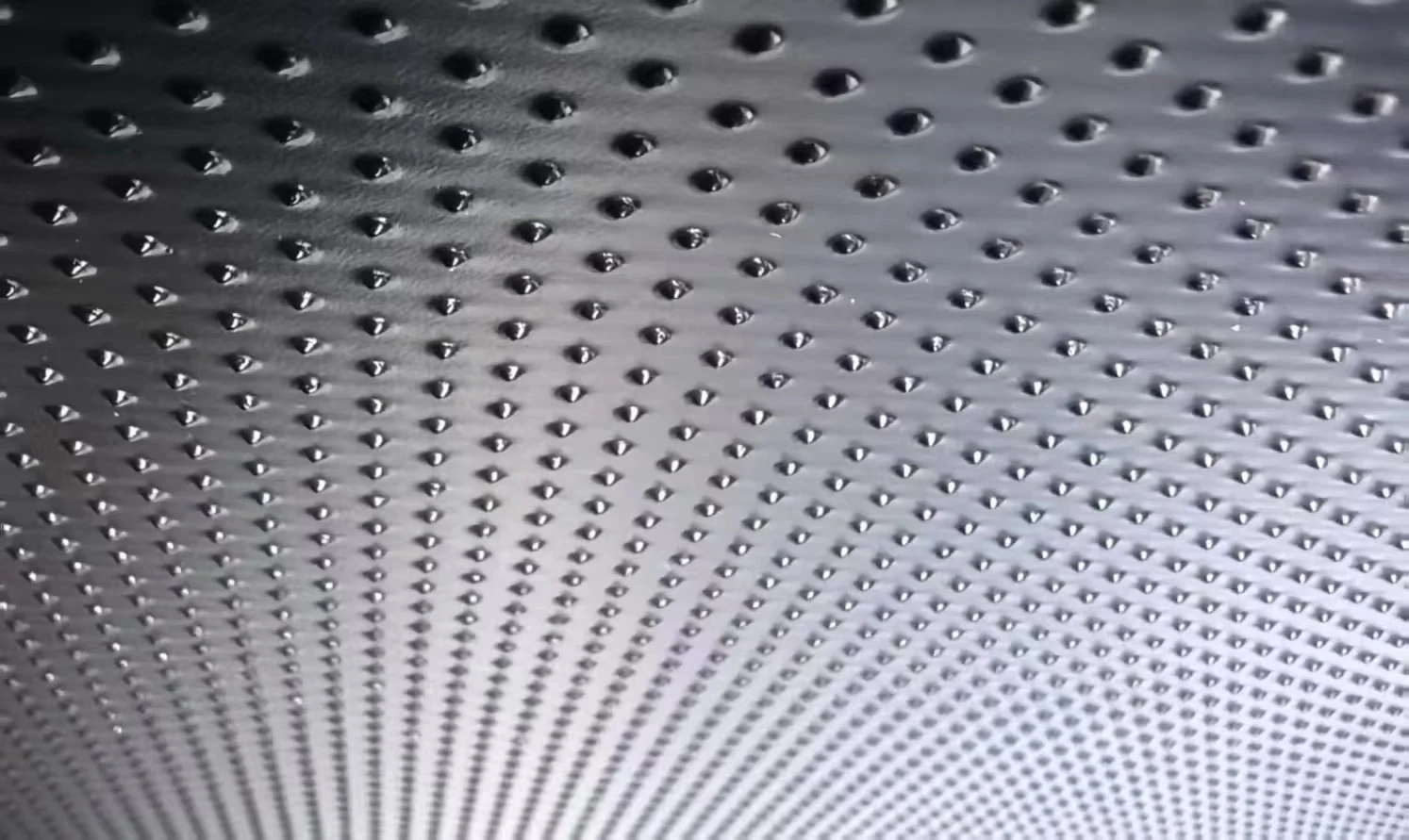
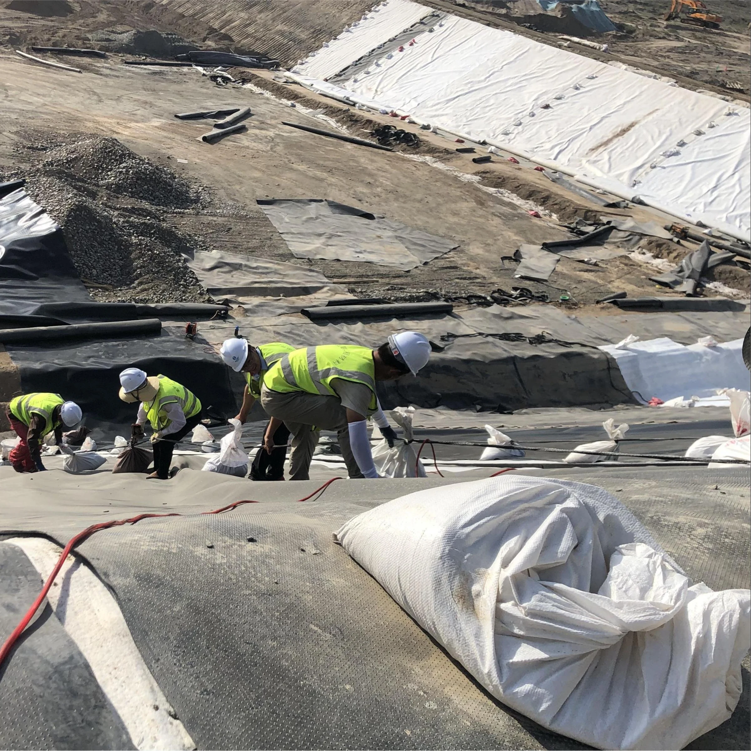
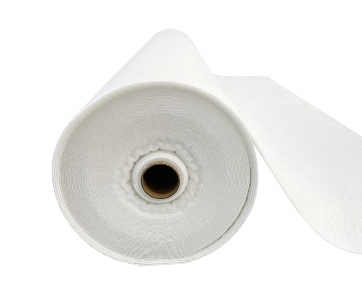

HDPE is a common first choice for brine ponds containing mainly inorganic salts, provided the specific membrane is suitable for the liquid chemistry and operating temperature. Compare LLDPE where the design requires greater flexibility. Select thickness and protection layers from the pond depth, ground conditions, settlement, and cleaning loads—not salt concentration alone.
For hot brine, solvents, or oxidizing chemicals, request compatibility and aging data for the proposed formulation before approving the material. A general “salt-resistant” rating does not establish suitability for those conditions.
Which Geomembrane Fits the Pond?
| Pond conditions | Material options | Selection criteria |
|---|---|---|
| Mainly inorganic salts; stable ground | HDPE geomembrane | Chemical compatibility at operating temperature, stress crack resistance, and aging performance |
| Uneven settlement remains after ground treatment | Compare HDPE and LLDPE liners | Calculated settlement, allowable strain, and movement at seams and pipe connections |
| Continuous hot brine or repeated hot discharges | A formulation tested under comparable conditions | Temperature, exposure duration, thermal cycles, and properties after immersion |
| Oil, solvents, or oxidizing chemicals in the brine | Materials supported by relevant compatibility tests | Chemical concentrations, contact time, and measured property changes |
| Mechanical salt harvesting or sludge removal | A membrane and protection system assessed together | Equipment contact pressure, travel routes, abrasion, and puncture resistance |
Where a pond crosses fill and natural ground, assess settlement before choosing the membrane. LLDPE cannot compensate for an untreated weak foundation. Laboratory elongation at break is not the allowable strain for an installed liner.
What Water Data Does the Supplier Need?
Submit analyses for both incoming water and concentrated brine. Include total dissolved solids (TDS), major ions, pH, and any oils, solvents, cleaning chemicals, or oxidizing agents. Identify separate cleaning and upset conditions rather than averaging them into normal operating data.
Record normal and peak temperatures, peak duration and frequency, and conditions near the inlet. A pond operating at 35°C with a two-hour peak at 60°C differs from one held continuously at 60°C. These are example exposure profiles, not product temperature limits. Exposed liner on the slopes also needs a separate weathering assessment.
100,000 mg/L equals 100 g/L, but not necessarily 10% by weight. At a brine density of 1.20 kg/L, 100 g/L corresponds to about 8.33% by weight. Mass fraction (%) = concentration (g/L) ÷ [density (kg/L) × 1,000] × 100. Thus 100 ÷ 1,200 × 100 = 8.33%. State the measurement temperature when reporting density and concentration.
If dissolved salt mass stays constant and no salt crystallizes, halving the liquid volume roughly doubles its concentration in g/L. Once crystallization begins, use the expected remaining liquid composition rather than extending that calculation indefinitely.
How Thick Should the Liner Be?
There is no thickness that suits every high-salinity pond. The comparison below uses an HDPE sheet density of 950 kg/m³ to show material quantities. The 1.5 mm and 2.0 mm examples are not a universal recommendation.
| Measure | 1.5 mm | 2.0 mm |
|---|---|---|
| Theoretical mass per square metre | 1.425 kg/m² | 1.90 kg/m² |
| Theoretical mass for 10,000 m² | 14.25 tonnes | 19.0 tonnes |
Theoretical mass per unit area = sheet density × thickness in metres: 950 × 0.0015 = 1.425 kg/m². Increasing thickness from 1.5 mm to 2.0 mm adds about 33% to material mass. It does not establish a proportional increase in service life. The weights exclude overlaps, anchorage, cutting waste, and thickness tolerances.
Brine with a density of 1,200 kg/m³ produces about 35.3 kPa of hydrostatic gauge pressure at a depth of 3 m—20% more than fresh water at the same depth. Using p = ρgh and g = 9.81 m/s² gives 1,200 × 9.81 × 3 = 35,316 Pa; fresh water at 1,000 kg/m³ gives 29.43 kPa. Continuous ground support matters: a void leaves the liner spanning a gap, while a protruding stone concentrates pressure on a small area.
For harvesting areas, assess the proposed ground, protection layer, and membrane assembly under representative loads. Specify a nonwoven geotextile protection layer by thickness and protective performance as well as mass per unit area. On slopes, choose smooth or textured membrane using interface shear tests with the actual adjacent materials.
What Proves Chemical Resistance and Durability?
A 2025 study examined five polyethylene geomembranes over eight years of immersion testing at temperatures from 25°C to 95°C. Under the conditions tested, higher salt concentrations slowed antioxidant depletion; temperature and formulation also affected durability. This finding supports testing the expected concentration range rather than assuming the most concentrated brine is always the worst exposure.[1]
Laboratory antioxidant depletion and accelerated aging results do not, by themselves, predict field service life. The study’s temperatures are laboratory conditions, not operating limits for commercial liners. A project report should identify the tested formulation, solution chemistry, temperature, exposure period, and initial and post-test properties. Any acceptance criteria should be agreed before testing.
GRI-GM13 sets manufacturing properties and testing frequencies for HDPE geomembranes, including stress crack resistance and antioxidant-related measures. It is a manufacturing quality specification, not a brine-pond design standard or proof of compatibility with a particular liquid.[2]
Compare oxidation induction time (OIT) results only when the test methods match. A high initial OIT or an unchanged appearance after a short soak does not establish a 20- or 30-year field life.
Liner System and Installation
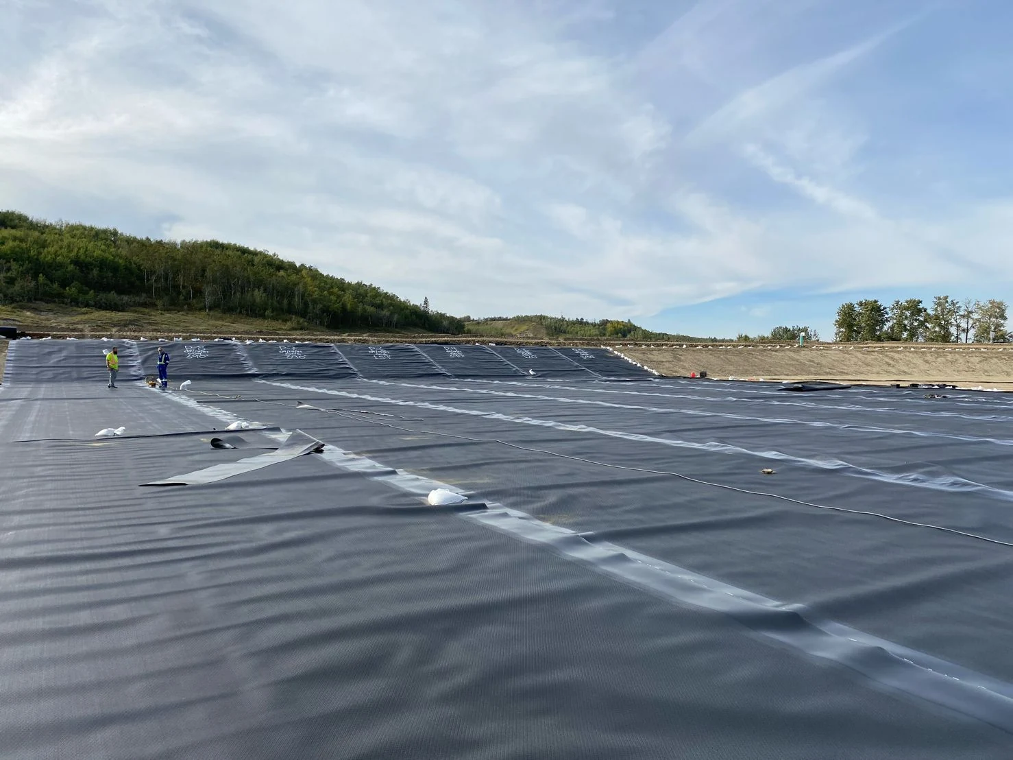
Permit requirements and the project risk assessment determine whether a second liner is needed. A double-liner system needs a measurable collection point for the leak detection layer. Its drainage design should account for salt deposits, blockage, and maintenance access.
If a geosynthetic clay liner is included, verify hydraulic performance with the actual brine. ASTM D6766-25 addresses hydraulic testing of geotextile-backed GCLs with potentially incompatible solutions and distinguishes prior water hydration from direct exposure to the test liquid.[3]
D6766 is not a chemical-compatibility test for an HDPE or LLDPE sheet; its scope also excludes geomembrane-backed, film-backed and polymer-coated GCLs. Use a suitable membrane compatibility protocol for the proposed geomembrane formulation.
- Groundwater and gas: Check uplift pressure when the pond is empty and provide drainage or venting where required.
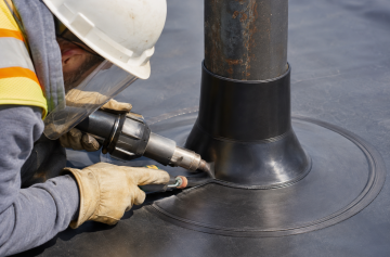
- Welds: Record trial-weld settings, peel and shear results, seam locations, repairs, and retests. Specify suitable inspection methods for hot-wedge and extrusion-welded seams.
- Pipe connections: Allow for movement between fixed pipes and the pond floor, and document the sealing details.
- Traceability: Link installed panels, seams, and repairs to roll batches and inspection records.
Seam tests do not detect every hole in the membrane. For liners covered with water or earth, ASTM D7007 describes electrical leak location procedures and the survey conditions needed for reliable detection.[4]
Compare Quotes on the Same Basis
For an illustrative rectangular pond, the bottom dimensions are 100 m × 50 m, vertical depth is 3 m and all four planar slopes are 3H:1V. The horizontal run is 9 m on each side, so the top dimensions are 118 m × 68 m. The slope length measured perpendicular to a side is √(9² + 3²) = 9.4868 m.
Geometric liner area = bottom + four trapezoidal slopes
= 100 × 50 + 2 × [(100 + 118)/2 × 9.4868] + 2 × [(50 + 68)/2 × 9.4868]
= 5,000 + 3,187.58 = 8,187.58 m² (about 8,188 m², or 8,200 m² rounded).
This geometry excludes top platforms, anchor trenches, overlaps, pipe details and cutting waste. Calculate procurement quantities from the panel layout and anchorage details; do not treat the rounded geometric area as the purchase order quantity.
Request separate prices for membrane supply, ground preparation, protection and drainage materials, installation, pipe details, testing, and transport. Specify the same quantities and inspection scope for every bidder.
Keep these three documents separate:
- Product data sheet: Identifies the proposed material, thickness, surface finish, and declared properties.
- Compatibility or aging report: Supports use of that formulation under the stated chemical and temperature conditions.
- Batch test certificate: Records manufacturing test results for the delivered material and provides roll or batch traceability.
The warranty should identify covered chemistry and temperatures, distinguish material defects from installation defects, and list eligible repair costs. Pond emptying, liner removal, reinstallation, and retesting may be excluded. For food salt production, obtain food-contact compliance documents applicable to the supplied formulation and intended use.
Cleaning and Leak Checks
Salt crusts can conceal damage and create hard contact points during cleaning. Define equipment routes, permitted tools, and protective measures before harvesting. Vehicles, buckets, and cutting tools should not contact bare membrane unless the design permits that specific loading.
Across a roughly constant water surface of 10,000 m², a 1 mm level drop represents about 10 m³ of water. Before attributing it to leakage, account for both level readings’ uncertainty, inflow, outflow, rainfall, and evaporation. Compare leak-detection water with pond brine and groundwater; conductivity alone cannot identify its source.
Inspect inlet scour areas, changing waterlines, pipe connections, anchor points, and harvesting routes. After emptying, check for uplift, unsupported membrane, and ground movement. Record defects by location so repairs can be added to the as-built drawings and retested.