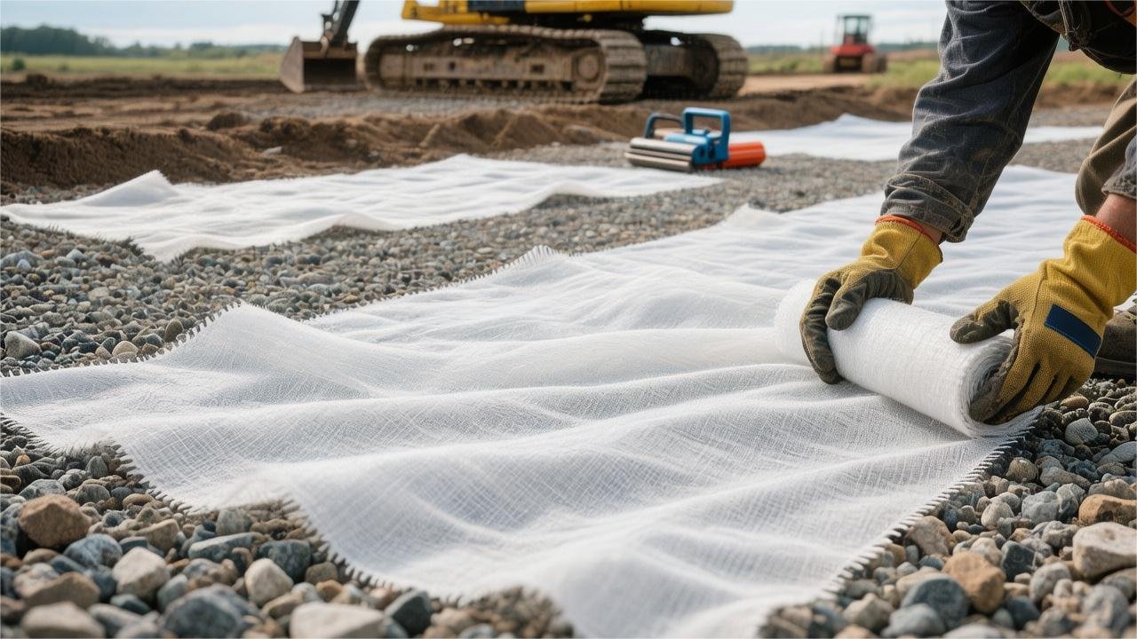
Non-woven geotextile fabric is commonly used in French drains, the back of retaining walls, or the base layers of private driveways to prevent gravel from sinking into the soil.
Unroll and lay the fabric after leveling the foundation. Adjacent joints must overlap by 30 to 45 cm and be secured with U-shaped landscape staples before backfilling with aggregate.
Do not use lightweight geotextiles below 8 ounces (approx. 270g/㎡) for load-bearing areas like driveways, as they tear easily; cover as soon as possible after laying to avoid UV aging caused by prolonged sun exposure.
Correct and standardized construction can double the engineering life and reduce post-maintenance costs by more than 50%.
Applications
The use of non-woven geotextile depends on its physical weight (usually 3 to 12 oz/sq yd) and water flow rate (110 to 150 GPM/sq ft). In residential and commercial civil projects, it primarily serves filtration, separation, and drainage tasks.
According to the US AASHTO M288 specification, lightweight 3 to 4 oz non-woven fabric is often used for French drains, with an Apparent Opening Size (AOS) capable of intercepting soil particles larger than 0.15 mm in diameter; heavy-duty fabric of 8 oz and above is laid under driveway gravel and can withstand a Grab Tensile Strength of over 220 lbs.
Subsurface Drainage Systems
In subsurface trenches excavated to depths of 18 to 36 inches, non-woven geotextile wraps perforated PVC pipes and washed gravel. Its permeability must meet the ASTM D4491 test standard, allowing 110 to 150 gallons (GPM) of water to pass through per square foot.
The permeability index ensures that surface and groundwater can rapidly merge into the 12 to 18-inch wide subsurface drainage channel during heavy rain. Once the water enters the aggregate voids, the three-dimensional fiber grid of the non-woven fabric begins to intercept suspended soil particles with diameters of 0.15 mm to 0.21 mm.
According to the application specifications of the American Road & Transportation Builders Association (ARTBA), different soil types must be matched with fabric of a specific Apparent Opening Size (AOS). In soils with a sand content exceeding 50%, non-woven fabric with an AOS of US Standard Sieve No. 70 must be used.
When facing clay content reaching 30% or silty geology, engineers specify 3.5 to 4.5 oz lightweight non-woven geotextile with an AOS of No. 100 to 120 (approx. 0.125 mm). Excessively large pore sizes will lead to fine particles penetrating and filling the internal gaps of the 3/4-inch gravel.
When excavating French drains, using 48-inch or 60-inch wide rolls of non-woven fabric can completely cover the bottom of the trench and the vertical walls on both sides.
- The laying tension of the fabric at the bottom of the trench should be controlled within an elongation of 15%.
- Before filling with aggregate, secure both edges of the fabric with U-shaped landscape staples every 3 to 5 feet.
- The width of the top overlapping fold is mandatory to be greater than 12 inches.
- The thickness of the natural soil backfill layer above needs to be maintained between 6 to 8 inches.
After completing the wrap construction (known in the industry as the “Burrito wrap” method), the 4-inch or 6-inch corrugated perforated pipe is completely isolated within an independent high-permeability space. The internal smoothness of the pipe, combined with the peripheral aggregate, can maintain a drainage speed of approximately 100 gallons per minute.
The pipe laying slope is executed at a drop of 1/4 inch per foot (approx. 1% to 2% inclination angle). Over time, a thin natural soil filter cake will form on the outer surface of the non-woven fabric, further blocking silt intrusion.
In the civil construction of Septic Leach Fields, non-woven fabric is used to protect the subsurface drainage chambers that distribute sewage below. Leach trenches are typically 24 to 36 inches deep, with at least 6 inches of washed graded gravel aggregate spread flat at the bottom.
After placing gravity distribution pipes or pressurized distribution pipes in the center of the gravel, the pipe body continues to be covered with 2 inches of gravel. Above this layer of gravel, a layer of non-woven geotextile with a unit weight of 3 oz/sq yd is laid flat.
In septic leach fields, it is not recommended to lay geotextile at the bottom and sides of the trench to prevent the overgrowth of biomat on the sides of the fabric, which would reduce the soil infiltration rate. The non-woven fabric at the top is specifically used to block the upper backfill soil from falling into the lower gravel layer during rain wash.
- The weight of the non-woven fabric used for septic leach fields needs to be less than 4 oz/sq yd.
- The vertical permittivity of the fabric needs to be maintained between 0.1 sec⁻¹ to 0.5 sec⁻¹.
- The lateral sides of the fabric must exceed the gravel edges by at least 2 inches.
Foundation Footing Drains around house foundations also rely on non-woven fabric filtration systems. Trenches are excavated next to the poured concrete footings, with depths set to 6 to 8 inches below the basement floor level.
Perforated PVC pipes placed in the trenches are used to collect hydrostatic pressure that causes dampness in basement walls. Each linear foot of the trench is filled with 2 to 3 cubic feet of 1.5-inch washed river stone, with the exterior fully sealed by needle-punched non-woven fabric.
The random three-dimensional fiber structure formed by the needle-punching process ensures that under soil gravity pressure of 300 psf (pounds per square foot), the internal physical porosity remains above 70%. The time for water molecules to permeate through the fabric pores is less than 0.5 seconds.
Dry Wells are underground storage facilities for handling residential roof downspout runoff. When a 50-gallon capacity plastic dry well tank is buried underground, a cylindrical space 12 to 24 inches larger than the tank needs to be excavated around it.
The excavated space is filled with large gravel aggregate, and the vertical interface between the aggregate periphery and the surrounding original soil must be lined with 4.5 oz non-woven fabric. The pore filtration ensures that rainwater slowly infiltrates from the dry well into the surrounding soil within 24 to 48 hours.
- The dry well installation location needs to be more than 10 feet away from the building’s concrete foundation.
- The air permeability (ASTM D737) of the non-woven fabric wrapping the peripheral aggregate needs to reach 50 cfm/ft².
- The physical overlap dimension at the fabric joints must reach 18 inches.
In the blind drain networks beneath Permeable Pavers, every 1,000 square feet of pavement produces up to 600 gallons of rainfall runoff. The bottom non-woven geotextile bears the heavy pressure of the 8 to 10-inch open-graded base aggregate above.
On soft clay foundations with a CBR (California Bearing Ratio) of less than 3, the non-woven fabric guides permeated water into the main underground drainage pipe while providing 115 lbs to 150 lbs of Trapezoidal Tear Strength.
Mesh drainage systems beneath golf course bunkers and sports field turf use flat strip drains with a width of 4 to 6 inches. The fabric is wrapped around the exterior of a plastic drainage core with pillar-like support structures.
USGA (United States Golf Association) specification documents stipulate that at the bottom of a 4 to 6-inch sand bed beneath a sports field, a layer of non-woven fabric with an AOS of No. 40 to 50 sieve is laid flat; when the tensile load reaches 90 lbs, the elongation is limited to within 50%.
Erosion Control
When the water flow velocity reaches 5 feet per second, hydraulic shear force will carry away sand and soil with diameters less than 2 mm from both sides of the riverbank. On slopes with inclinations of 2:1 or 3:1, the annual loss rate of unprotected surface soil is as high as 20 to 50 tons per acre.
US Army Corps of Engineers (USACE) guidance documents state that before laying Riprap with individual weights of 50 to 300 lbs for bank protection, the slope base must be lined with non-woven geotextile weighing 8 to 12 oz/sq yd.
A polypropylene fiber layer with a physical thickness exceeding 80 mils (mils) disperses the impact force brought by the water flow to the soil below, preventing 6 to 18-inch heavy rocks from sinking into soft mud over time.
According to ASTM D4355 UV resistance testing, non-woven fabric exposed to sunlight must still maintain 70% of its tensile strength after 500 hours. During construction, the fabric is spread along the direction of water flow, and the upstream edge must be pressed over the downstream edge.
The overlap width at the joints is strictly set between 24 to 36 inches. Construction personnel use steel U-shaped anchors with lengths of 12 to 18 inches to fix the fabric to the inclined slope at a density of 1 anchoring point per square yard.
To prevent water from tunneling under the fabric edges during flood periods and causing bottom scouring, anchor trenches with a depth of 18 to 24 inches and a width of 12 inches must be excavated at the top and bottom of the slope.
Bury the edges of the non-woven fabric completely into the anchor trenches and backfill with compacted graded gravel. The physical closure system can withstand flood scouring velocities of 12 feet per second, cutting off the path for water to carry soil away from under the fabric.
In the construction of artificial lakes or stormwater detention ponds, the bottom waterproof layer often uses 45-mil thick EPDM rubber membranes or 30-mil PVC geomembranes. When the pond is filled to a depth of 8 feet, the bottom will bear nearly 500 lbs of hydrostatic pressure per square foot.
Sharp 0.5-inch gravel, waste glass fragments, or tree roots with diameters exceeding 1 inch mixed in the original soil can easily puncture the high-density polymer waterproof membrane under continuous water pressure squeezing.
Laying heavy-duty needle-punched non-woven geotextile with a unit weight of 8 to 10 oz/sq yd under the geomembrane serves as a high-strength Cushion Underlayment.
| Underlayment Application Scenario | Recommended Fabric Weight (oz/sy) | CBR Puncture Resistance (lbs) | Physical Apparent Thickness (mils) |
|---|---|---|---|
| Residential Backyard Koi Pond | 6.0 – 8.0 | 400 – 550 | 70 – 80 |
| Golf Course Artificial Lake | 10.0 – 12.0 | 700 – 850 | 100 – 110 |
| Industrial Wastewater Detention Pond | 16.0 | > 1000 | 140 – 150 |
According to the ASTM D6241 test standard, 10 oz non-woven fabric has a CBR puncture resistance of up to 700 lbs. The three-dimensional fiber structure up to 100 mils thick absorbs the local stress of sharp objects, preventing their tips from contacting the waterproof membrane above.
After the excavator digs to the design depth and clears large rocks from the surface, rolls of geotextile are manually spread along the pond bottom and inclined walls. The physical overlap joints of two adjacent rolls are required to reach 6 to 12 inches.
For commercial-grade ponds exceeding 10,000 square feet, construction personnel use handheld heat guns to perform spot thermal fusion welding on the overlapping edges of the geotextile, with welding points physically spaced every 24 inches.
On steep artificial lake walls with inclinations greater than 3:1, contractors often lay another layer of 8 oz non-woven fabric above the EPDM waterproof membrane, forming a double-sided sandwich protection structure.
- The upper fabric layer reaches a thickness of 80 mils, preventing the 12-inch natural pebbles subsequently filled for pond bottom aesthetics from scratching the rubber membrane under gravity.
- The friction angle provided by the rough fabric surface reaches 28 degrees, increasing surface resistance and preventing large-scale landslides of the soil covering the membrane.
- The double-layer fabric isolation structure eliminates physical puncture risks, extending the lifespan of the geomembrane from 15 years to over 30 years.
In the construction of landfill liner systems, high-density polyethylene (HDPE) textured geomembranes typically have a thickness of 60 mils. The lower base protection layer utilizes ultra-heavy-duty non-woven geotextile with weights of 12 to 16 oz.
16 oz fabric weighs nearly 1 lb per square yard and possesses the attribute of resisting impacts of over 1,000 lbs generated during waste dumping. The internal porosity of the fabric remains around 30% even under ultra-high waste compression loads of 15,000 psf.
When high-concentration leachate accumulates at the bottom of the landfill, the 1.0 sec⁻¹ vertical permittivity of the non-woven fabric ensures the liquid rapidly passes through the fabric into the bottom blind drain network.
Landfill areas generate 1,000 to 3,000 gallons of leachate per acre per day. The three-dimensional labyrinthine fiber network of the thick fabric physically intercepts suspended solid municipal waste particles, preventing the wall holes of the 6-inch outer diameter HDPE perforated collection pipes from clogging.
In breakwater projects along coastlines, 12 oz to 16 oz non-woven fabric is often sewn into sand-filled Geotextile Tubes. Each tube, up to 100 feet long, weighs over 500 tons when filled with silt.
The high-tensile strength non-woven fabric shell resists day and night physical battering from 40 mph sea winds and 3-foot high waves. The Grab Tensile Strength of up to 380 lbs ensures that the tubes maintain their original shape without deformation or rupture under extreme tidal water pressure.
Retaining Wall Drainage
Water weighs 62.4 lbs per cubic foot. When the backfill soil behind a retaining wall reaches 100% saturation, the back of a 4-foot high, 20-foot long retaining wall will bear tens of thousands of pounds of additional lateral hydrostatic pressure.
National Concrete Masonry Association (NCMA) engineering specifications clearly state that the only physical way to release water pressure is to establish a 12 to 24-inch wide vertical gravel drainage layer between the wall structure and the retained soil.
Vertically laying non-woven geotextile at the interface between soil and gravel can reduce the risk of retaining wall base overturning by more than 60%.
The non-woven fabric acts as a two-way physical barrier here. It allows 110 gallons per minute/square foot (GPM/ft²) of water to pass through the fiber mesh into the gravel layer, while intercepting fine soil particles larger than 0.15 mm in diameter.
Under the ASTM D4491 test standard, 4 oz to 6 oz weight non-woven fabric has a permittivity of 1.5 sec⁻¹ to 2.0 sec⁻¹. The high permittivity ensures that surface runoff generated by heavy rain can permeate to the base of the wall within 30 minutes.
Without geotextile isolation, silt and clay particles in the backfill soil will permeate with rainwater within 3 to 5 years, filling approximately 40% of the physical voids inside the 3/4-inch clean angular gravel.
Construction laying needs to start from the original soil layer at the bottom of the excavated trench. Personnel spread rolls of non-woven fabric with widths of 48 inches or 72 inches along the trench floor and extend them upwards along the vertical excavated faces.
- Reserve 18 to 24 inches of fabric at the bottom to be spread under the footing base.
- Reserve more than 12 inches of fabric at the top for the final capping cover.
- When splicing two sheets of fabric is necessary, the vertical overlap must be at least 18 inches.
A layer of base gravel with a thickness of 2 to 4 inches is placed on top of the fabric at the bottom of the trench. A perforated corrugated PVC pipe with an outer diameter of 4.215 inches is placed in the center of the gravel at a 1% slope.
Engineers generally do not recommend wrapping the bottom drainage pipe alone with non-woven fabric. Wrapping the pipe alone causes the clogging surface area around the pipe wall to plummet to approximately 150 square inches per linear foot.
The standard practice is to push the isolation interface out to the contact surface between the original soil and the drainage aggregate. The non-woven fabric is held tight against the rear soil, and the interior is filled with open-graded aggregate level with the height of the wall.
Stop aggregate filling at approximately 8 inches below the top of the wall. Fold the reserved top geotextile horizontally toward the wall, completely closing it over the top of the gravel layer.
The top fold treatment blocks the 6 to 8-inch low-permeability surface clay used for planting lawn. The clay layer seals surface water, while the fabric prevents mud from leaking down into the drainage gravel layer.
For fine-grained soil environments containing more than 40% clay, 4.5 oz non-woven geotextile with an AOS (Apparent Opening Size) of US Standard Sieve No. 100 to 120 exhibits excellent anti-clogging performance.
Needle-punched polypropylene fibers with thicknesses of 60 to 80 mils can still maintain over 45% of internal physical pores without being compacted when subjected to 300 to 500 lbs per square foot of lateral pressure from the soil behind the wall.
In some heavy Segmental Retaining Wall (SRW) projects with height differences exceeding 6 feet, a piece of unidirectional geogrid is inserted horizontally every 3 to 4 feet in vertical height, passing through the gravel layer and anchored in the backfill soil.
The fabric must be cut with a utility knife to create a straight slit where the geogrid passes through, and the upper and lower gaps after the grid passes must be reinforced and overlapped by 6 inches with extra fabric patches.
A Weep Hole penetrating the blocks is set every 10 to 20 feet at the bottom of the wall. The front end of the pipe section inside the weep hole also needs to be lined with a piece of 4 oz non-woven fabric as a terminal filter.
Grab Tensile Strength of up to 150 lbs prevents sharp stones from tearing the vertical isolation fabric during the soil compaction phase by heavy machinery.
If the original slope has underground springs or continuous seepage layers, the contractor will install Geocomposite Strip Drains in parallel contact with the deep soil layer at the back.
- The outer wrapping layer of the composite drainage net uniformly adopts polypropylene non-woven fabric with an AOS of No. 70 sieve.
- The drainage strip can handle 20 to 30 gallons of deep groundwater per foot.
- The flatness error requirement for the fabric surface in contact with the excavated soil is controlled within 1 inch.
Correct installation specifications ensure that the hydrostatic pressure readings on the back of the wall always approach 0 lbs/sq ft.
Step-by-Step Installation
Installing non-woven geotextile requires following clear physical parameters and construction standards. Construction requires the subgrade soil to reach 95% Standard Proctor Density compaction. The fabric overlap width depends on the soil California Bearing Ratio (CBR): medium-hard soil with a CBR greater than 3 requires an overlap of 12-18 inches, while soft soil with a CBR less than 1 must overlap by more than 36 inches.
Securing materials should use 6 to 8-inch long 11-gauge U-shaped steel staples, with spacing maintained at 3 to 5 feet. When backfilling coarse aggregate such as #57, the mechanical dump drop height is strictly limited to within 3 feet to prevent instantaneous impact forces from puncturing the non-woven fabric, which typically has a puncture resistance of 60-120 lbs.
Subgrade Excavation
The excavation depth for standard permeable driveway projects is typically set at 12 to 18 inches below surface grade. Operating a 20-ton crawler excavator equipped with a 36-inch wide smooth-edge bucket for earthwork can control the bottom elevation error within 0.5 inches.
Excavation must avoid underground utilities; according to the 811 marking system, the bucket must maintain at least a 24-inch physical buffer from high-pressure natural gas pipes buried at 36 inches.
After the excavation face is exposed, debris must be screened out manually or via mechanical rakes. Sharp rock fragments with diameters exceeding 2 inches and exposed tree roots with diameters greater than 1.5 inches in the subgrade soil must be completely removed.
Soil samples for organic matter content must be sent to a lab for Loss on Ignition testing following ASTM D2974. Surface black soil or peat soil with an organic weight ratio exceeding 3% must be deeply excavated and stripped.
Remaining organic matter will undergo volume shrinkage during the 6 to 12-month biodegradation process, leading to local subsidence depressions of over 2 inches in the upper geotextile.
- Clean all humus layers to a depth of 6 inches below the ground surface.
- Remove plant taproots with remaining lengths exceeding 4 inches.
- Backfill with inorganic structural soil with a pH between 6.0 and 8.0.
- Screen out expansive clay with a Plasticity Index (PI) greater than 20 that accounts for more than 15%.
The cleaned subgrade surface needs slope mapping using a Laser Grader. For a 20-foot wide one-way slope driveway, the lateral drainage slope needs to be set at 1.5% to 2.0%.
Level the surface according to a ratio of 0.25 inches of drop per horizontal foot of extension. If there are puddles or ruts deeper than 3 inches in the subsoil, they need to be filled and leveled with graded gravel.
Surface water generated by rain that remains under the non-woven fabric for more than 48 hours will cause the moisture content of silty loam to rise to saturation. The California Bearing Ratio (CBR) of the subsoil will plummet from 8 in a dry state to below 1.5.
The Optimum Moisture Content (OMC) of the soil layer is the physical parameter that determines the efficiency of compaction machinery. Field soil moisture content must be controlled within ±2% of the laboratory Standard Proctor Test data.
When the soil is too dry and crumbles when squeezed, a water truck must be used to humidify at a rate of 50 to 80 gallons per 1,000 square feet. For muddy sites with moisture content exceeding the optimum by 4%, exposure to sunlight for 24 to 48 hours is required.
Different grain-graded subsoils require matching specific amplitudes and tonnages of rolling equipment.
| Subsoil Physical Classification (USCS Standard) | Applicable Compaction Machinery Parameters | Passes and Speed Limits | Target Compaction Requirement |
|---|---|---|---|
| Poorly graded sand (SP) | 1.5 to 3 ton vibratory tandem roller | 3-4 passes, max 2 mph | 95% Modified Proctor |
| Low plasticity silt (ML) | 500 lb plate compactor with 5,000 lb centrifugal force | 4-5 passes, max 1.5 mph | 92% Standard Proctor |
| High plasticity clay (CH) | 5 to 8 ton Sheepsfoot roller | 5-6 passes, max 2.5 mph | 90% Standard Proctor |
After rolling operations, quality inspectors will perform grid sampling in the excavation area. In-situ soil testing is conducted using a Dynamic Cone Penetrometer (DCP), recording the inches of penetration for every fall of the 17.6-pound weight.
DCP test data (mm/blow) will be converted to CBR values. If the converted CBR values for three consecutive points are below 3, it indicates the subgrade compaction failed to meet the standard.
Nuclear density gauge probes based on the ASTM D6938 standard are driven 8 inches into the soil layer. Only when the dry density reading exceeds 115 lbs/ft³ does the subgrade meet the physical conditions for laying 8 oz non-woven geotextile.
- Perform at least one DCP probe test every 2,500 square feet.
- Level a 12×12 inch area before nuclear density testing.
- The relative elevation error of test points must not exceed 0.1 feet.
- Compaction testing on frozen soil is prohibited when the temperature is below 32°F (0°C).
The qualified subgrade surface should exhibit a hard and smooth texture. For personnel walking on it, the indentation depth from the heel of a work boot must not exceed 0.25 inches.
A heavy dump truck driving at 10 mph on the compacted subgrade should not cause visible elastic deformation of the soil surface due to the pumping effect generated by the tires.
The prepared excavation face must be covered with non-woven geotextile within 72 hours. If exposed subsoil encounters a short-term heavy rain exceeding 0.5 inches, surface fine-grained soil will be washed away.
Spreading and Overlapping
Standard commercial rolls of non-woven geotextile are typically 12.5 feet or 15 feet wide and 360 feet long. A 15×360 foot roll weighs between 250 and 300 lbs. Spreading at the site should use mechanical equipment with spreaders. Forcefully dragging manually will damage the internal needle-punched structure, reducing the original 100 gpm/ft² permeability.
The spreading direction should be consistent with the direction of subsequent aggregate dumping or vehicle travel. Apply a tension of 10 to 15 lbs per linear foot to the fabric during operation to keep the surface taut. Folds exceeding 2 inches in thickness will form structural stress weak points when subjected to 10-ton vibratory roller operations.
Wind speed objectively limits the progress of spreading. Stop laying when sustained wind speeds exceed 15 mph. Wind lift is sufficient to lift and shift an unanchored 12.5-foot wide roll. Use sandbags weighing approx. 30 lbs every 20 feet for temporary weighting during spreading.
- The spreading path should be parallel to the centerline of the subgrade.
- The maximum allowed slack per 10 feet of distance is 1 inch.
- The outer diameter of the spreader’s steel pipe should reach 3 inches to prevent core deformation.
- Unused rolls should be stored horizontally on dunnage 6 inches above the ground.
The overlap width of adjacent rolls is strictly determined by the subgrade soil California Bearing Ratio (CBR). Solid subgrades with a CBR greater than 3 require a minimum overlap width of 12 to 18 inches. Well-drained gravel sand or compacted aggregate bases typically meet these parameters.
For medium-strength subsoils with CBR values between 1 and 3, overlap requirements increase to 24 to 36 inches. Most silty loam mixtures fall within this bearing range. The expanded overlap surface is designed to compensate for slight subgrade rutting; subsoil ruts can reach 3 to 4 inches deep when fully loaded dump trucks pass.
Ultra-soft soil layers with a CBR below 1 must execute a 36-inch overlap standard. Saturated clay or swampy plots exhibit extremely low bearing capacity. In such high-moisture environments, simple physical overlaps easily fail, and joints must be sewn using industrial portable sewing machines.
- Adopt Federal Standard Type 401 double-thread chain stitch.
- The thread tension must maintain a minimum tensile strength of 30 lbs.
- The stitch density is controlled at 3 to 7 stitches per inch.
- The stitch position is within 2 to 4 inches of the fabric edge.
- Use high-strength Polypropylene industrial thread.
The UV and chemical corrosion resistance ratings of the thread must be equal to or higher than the geotextile itself. 2000 Denier polypropylene thread is a standard configuration. Cotton or nylon thread will undergo rapid degradation in alkaline soils with a pH greater than 8.
The overlap direction of joints must follow the “roof shingle” water-shedding principle. In the direction of aggregate advancement, the edge of the previous roll must be pressed over the edge of the subsequent roll. Forward overlapping eliminates the physical risk of aggregate waves cutting into the gap and prying the two layers apart.
Handling curved areas requires the radial folding method. Along the construction path, fold the outer edge toward the inner side. Secure the fold with 8-inch long U-shaped staples. Before aggregate coverage, the height of radial folds must not exceed 6 inches to prevent local stress concentration during subsequent rolling.
- At sharp turns, rolls can be cut into trapezoidal segments for laying.
- Staple the folds on the inner radius every 12 inches.
- Maintain a 24-inch minimum physical overlap at radial joints.
- Forcefully stretching fabric on the outer radius is strictly prohibited.
On slopes with gradients exceeding 3:1, horizontal joints are strictly prohibited. Rolls must be spread vertically down the slope. Upward segments must overlap downward segments, with a uniform minimum overlap margin set at 24 inches.
Anchoring Layout
Anchoring requires the use of 11-gauge or thicker industrial steel U-shaped staples. Carbon steel staples with a wire diameter of 0.1205 inches can penetrate a 95% compacted subgrade without bending. The width of the top U-bridge should be maintained between 1 to 2 inches.
A narrow top will cut the three-dimensional fiber grid of the non-woven geotextile, causing a 15% drop in local tensile strength. Hot-dip galvanized staples have a rust-proof life of up to 10 years in slightly acidic soils with a pH of 5.0.
- Hard clay layers with a CBR greater than 3 use standard 6-inch staples.
- Medium-dense loams with a CBR between 1 and 3 require 8-inch extended staples.
- Long staples of 10 to 12 inches must be driven into loose sand or high-moisture mud.
- An average of 150 to 200 staples are consumed per 1,000 square feet of laying area.
For flat construction sites with wind speeds below 5 mph, staple spacing along the longitudinal edges of the rolls is set at 3 to 5 feet. At overlapping joints, staples must penetrate two layers of non-woven fabric with an average thickness of 100 mils.
The staple spacing at the joint centerline should be shortened to 2 to 3 feet. Staggered stapling further improves the material’s pull-out resistance. Each subsequent staple is offset from the axis of the previous one by approx. 2 inches, forming a zigzag pattern.
Each 11-gauge staple penetrating dual layers of fabric provides approx. 25 lbs of static slip resistance horizontally, effectively resisting thrust generated during the early stages of backfilling the first gravel layer.
Terrain slope changes the gravity distribution, and spacing parameters must be adjusted accordingly. On a gentle slope of 4:1 (horizontal:vertical), grid-patterned staple spacing is fixed at 3 feet. When the slope reaches 3:1, both lateral and longitudinal spacing are reduced to 2 feet.
Facing steep 2:1 terrain, a physical anchoring point must be placed every 1.5 feet. Anchor trenches at the top of slopes are typically excavated 12 inches wide and 12 inches deep. After the geotextile extends to the bottom of the trench, a long staple is driven every 1 foot.
- Stapling requires a rubber mallet with a head weight of 16 to 24 ounces.
- Metal hammers easily break fibers with a single strike, reducing the puncture point’s tear load by 50%.
- The drive angle must be absolutely 90 degrees vertical to the ground.
- The top of the staple must be flush with the geotextile surface, with no gaps left.
Open work faces exposed to weathering need dynamic anchoring density adjustments. When site anemometers measure instantaneous gusts reaching 20 mph, the windward edges of the fabric generate approx. 1.5 lbs of upward aerodynamic lift per square foot.
At this time, edge staple spacing must be shrunk to 1 foot. When laying 15-foot wide large rolls in open valleys, 40-pound sandbags should be placed every 10 feet for gravity weight in addition to mechanical anchoring.
Anchor arrays exposed for more than 24 hours must undergo 100% manual re-inspection before aggregate arrival if subjected to heavy rain exceeding 1 inch.
Heavy machinery operations during subsequent backfilling stages apply extreme shear forces to the anchoring network. A fully loaded dump truck weighing 50,000 lbs braking on a 6-inch aggregate cushion applies massive horizontal traction to the base geotextile.
If staple spacing at joints exceeds 3 feet, horizontal force will pull the joint apart by at least 4 inches. Supervisors should randomly select 10-foot sections along joints to ensure they contain at least 4 galvanized U-staples fully anchored.
In loose silty soil, standard U-staples are prone to sinking or being pulled out. Construction needs to switch to single-pin staples with 1.5-inch diameter High-Density Polyethylene (HDPE) washers. Washers increase the downward bearing area by 300%.
- Use a digital force gauge to pull fixed staples and test vertical pull-out resistance.
- A single 8-inch staple in compacted clay must exceed 45 lbs of pull-out resistance.
- Areas with pull-out resistance below 30 lbs must have staples replaced with those 2 inches longer.
- Alternatively, supplement with two U-staples at cross angles within 4 inches of the original point.
Holes left after incorrect staple removal must be repaired. A 0.12-inch staple hole will allow silt particles over 75 microns to penetrate the isolation layer under water pressure. Pull-out areas should be double-sealed with 3-inch square polyurethane tape.
The time gap between the completion of overall anchoring and the coverage of the first aggregate layer must be controlled within 72 hours. Long-term UV exposure weakens polypropylene fiber tensile strength, and weathering causes approx. 2% of edge staples to loosen slightly daily.
Aggregate Backfilling
First-lift aggregate dumping requires front-end loaders or dump trucks to strictly follow drop limits. When using standard #57 gravel (particle size 1 to 1.5 inches), the bottom of the bucket must not exceed 3 feet (approx. 0.9 m) from the laid geotextile surface.
Free-fall motion from above this height generates instantaneous impact force exceeding 120 lbs per square inch. 8 oz non-woven fabric with a thickness of 80 mils typically maintains an ASTM D4833 puncture strength in the 115 to 130 lbs range; sharp granite aggregate dropped from excessive heights can easily pierce it.
- Dumping should advance from edges or areas with existing cushions.
- Single dump volumes are limited to within 3 to 5 cubic yards.
- Emptying a 15-ton truck bed directly onto uncovered fabric is strictly prohibited.
- The initial height of the aggregate pile must be below 24 inches.
Subgrade CBR data defines the minimum thickness standard for the first aggregate lift. On solid subgrades with a CBR greater than 3, the uncompacted thickness of the first lift must be maintained at 6 inches (15 cm) for standard construction vehicles.
If the CBR value decays to between 1 and 3, the cushion thickness must increase to 9 to 12 inches. For swampy or saturated clay environments with CBR less than 1, safe operation for tracked dozers requires a cushion of 18 to 24 inches.
Ground contact pressure of heavy machinery defines its safe range of operation on the cushion. A Cat D6 class medium dozer generates approx. 4.5 to 6.0 psi of track pressure.
When using a dozer to level aggregate, the blade must maintain at least a 3-inch safety clearance above the geotextile surface. Tracked equipment must always drive in a straight line on the laid aggregate; pivot steers generate immense physical shear force instantly.
- Dozer travel speed is strictly limited to below 3 mph.
- Tracks must never contact bare non-woven fabric not covered by aggregate.
- Emergency braking is not allowed on cushions thinner than 6 inches.
- The minimum turning radius for U-turns must be greater than 30 feet.
- Avoid longitudinal slopes exceeding 15 degrees on the construction route.
Rut depth after leveling is a physical parameter for monitoring the stress state of subgrade and geotextile. If rut depth after a loader passes the first lift exceeds 3 inches, it indicates insufficient subgrade bearing or too thin an initial cushion.
At this time, it is prohibited to use a motor grader to scrape the mounds on either side of the rut into the trench. The compliant procedure is to call for extra #411 graded gravel or Crusher Run to fill the rut and relevel.
The compaction phase needs to switch vibratory modes based on the subgrade moisture content. On ultra-soft layers with CBR below 1, the first aggregate lift can only use 10-ton class static rollers for static rolling.
Turning on high-frequency vibration up to 30 Hz on soft soil will pump underlying silt to the fabric surface. The 100 gpm/ft² micropores will be instantly clogged by 50-micron class soil fines.
- Use static rolling for 2 to 3 passes for the first lift.
- Low-frequency vibration can only be started after the second lift reaches 6 inches.
- Roller amplitude should be set below 0.015 inches.
- Adjacent rolling tracks must overlap by at least 6 to 8 inches.
When total aggregate thickness reaches 12 inches or more, large plate compactors or single-drum rollers can switch to regular frequency. Compacted aggregate density must reach 95% Modified Proctor dry density.
Contractors will use nuclear density gauges every 50 feet for probing. If an area’s compaction stays at 88% to 90%, the underlying polypropylene fibers may have undergone over 20% excessive tensile deformation.
Wrapping and Sealing
Standard French drain excavation dimensions are typically set at 18 inches wide and 24 inches deep. When using a single 12.5-foot wide roll of fabric to line the bottom and side walls, at least 24 to 36 inches of loose fabric must be reserved on both sides of the trench top.
Place a layer of #57 washed gravel cushion 2 to 3 inches thick at the bottom, then place the SDR-35 or Schedule 40 perforated PVC pipe (4.215″ OD). Continue backfilling the top and sides with the same permeable gravel.
Gravel backfill height cannot be flush with the surface; it must stop 3 to 4 inches below grade.
- Silt content of gravel is strictly limited to below 2% of total weight.
- Porosity must reach 35% to 40% to maintain flow.
- Granite aggregate with a Mohs hardness of 6 to 7 is typically used.
- Avoid limestone gravel with a pH higher than 8.0.
Fold the reserved fabric from one side of the trench inward over the gravel top. Then pull the other reserved fabric to cover over the first layer like an envelope. The top physical overlap width is mandatory at 12 to 18 inches.
The top dual-layer overlap must be physically locked with 6-inch 11-gauge U-staples. Along the trench centerline, drive a staple every 3 feet (approx. 0.9 m), penetrating both layers of 80-mil fabric and anchoring into the gravel.
Wrapping at T or Y trench junctions is extremely complex. Fabric margins from all four sides must be fully unfolded and layered according to water flow direction; overlaps at junctions should expand to over 24 inches.
- Apply 3-inch wide double-sided butyl waterproof tape at joints.
- Increase staple density at junctions to one every 12 inches.
- Upstream fabric must be pressed over downstream fabric.
- Use single-sided acrylic tape for external physical edge sealing at miter cuts.
The completed drainage wrap will be briefly exposed to natural light. Polypropylene fiber tensile strength drops 30% after 14 days of all-weather UV exposure. Topsoil coverage must be completed within 72 hours of sealing.
Fill the top of the wrapped fabric with 3 to 4 inches of a coarse sand and topsoil mixture. The particle diameter of the mixture must be larger than the fabric’s 75-micron AOS to prevent powdery soil from entering pores with surface water.
The cover layer should be compacted with a 200-lb hand tamper or light plate compactor. Organize a 1% to 2% drainage slope on the surface to guide runoff away to lawns or low spots on either side.
Bare soil on-site without vegetation will generate massive mud runoff when rainfall hits 0.5 inches per hour. Uncovered trenches require 24-inch high Silt Fences 10 feet away.
- Set 8-inch diameter Compost Filter Socks above slopes.
- Intercept surface wash water at speeds up to 10 gpm/ft.
- Keep interceptors at least 5 feet from the drain edge.
- Temporary high-viscosity wet soil piles are prohibited on the wrap.
The closed trench system needs cleanouts every 50 feet. 4-inch OD vertical PVC risers must penetrate the top dual fabric layers. Gaps around penetrations must be locked to the riser wall with polyurethane sealant and stainless steel hose clamps.
When the drain connects to a 4x4x4 foot Dry Well, the pit must also be wrapped. Hydrostatic pressure at the pit bottom can hit 150 psf, requiring an upgrade to heavy-duty 12 oz fabric over 120 mils thick.
The fold method at the dry well top is the same as the trench, with 36-inch overlaps on all four sides. Topsoil cover thickness is increased to 18 inches to use soil weight against upward buoyancy when water tables rise.
Mistakes to Avoid
Mistakes in installing non-woven geotextile lead to physical system failure. Engineering stats show over 70% of French drains clog within 5 years due to using fabric under 4 oz or overlaps less than 12 inches (30 cm).
Additionally, exposing fabric to sunlight beyond its rated UV days before backfill drops tensile strength by over 40%. This section lists parameter errors violating AASHTO M288 to ensure a 25+ year lifespan.
Substandard Overlap Dimensions
Roll widths are typically 12.5 or 15 feet. On level, hard, compacted subgrade, the overlap must be 12 to 18 inches (30-45 cm). Gaps under 12 inches will slide apart under the 6,000-lb static track pressure of a small excavator.
Overlap dimensions must adjust with geological changes. AASHTO M288 provides mandatory metrics based on CBR. Soft, moisture-rich peat soil magnifies shear forces from above, pulling joints from the bottom.
- CBR > 3: Min overlap 12-18 inches (30-45 cm).
- CBR 1-3 (Soft soil): Requires 24-36 inches (60-90 cm) overlap.
- CBR < 1 (Swamp): Abandon physical overlap for high-strength double-thread sewing.
When laying on a slope, the uphill fabric must overlap the downhill fabric. Following the roof shingle principle, 5 gpm/ft² surface runoff slides over the fabric, bypassing joints.
Trench closure (like French drains) requires millimeter precision. For a 24-inch deep trench, reserved fabric flap widths must be at least 18 inches (45 cm). Fold the right flap left, then the left flap right; the overlap must cover 100% of the trench width.
Overlaps alone cannot resist the impact of falling soil during backfill. 11-gauge galvanized U-shaped Landscape Staples must be used. Unfixed joints will curl up to 8-10 inches when 1.5-inch gravel is dumped.
- Flat terrain/standard soil: Use 6″ long, 1″ wide U-staples.
- Slopes > 3:1: Switch to 8″ or 10″ staples.
- 15 mph wind zones: Add 2 extra points per square yard.
- Drive angle: 90 degrees vertical, flush with fabric.
Staple spacing is defined by slope. On slopes < 4:1, on-center spacing is 3-5 feet (0.9-1.5 m). Drive a single line of staples through the overlap centerline, penetrating both layers.
On retaining wall slopes (> 4:1 but < 2:1), density increases. On-center spacing drops to 2-3 feet (0.6-0.9 m) using a staggered double-row method. Rows are 6″ apart in a Z-pattern to resist the 2,800-lb downward thrust of wet soil.
Corner handling needs specific folding. In 90-degree turns, inner fabric piles up while outer fabric is stretched. After outer curve cuts, overlaps must follow water flow with edges at least 20 inches (50 cm) and 8″ staples at three geometric vertices.
- Outer curve tension: Cut 8″ slits every 3 feet along the edge.
- Inner curve fold: Fold excess into flat triangles and press down.
- Curve staple density: Spacing drops from 5′ to 1.5′ (45 cm).
- Tension relief: Reserve 2 inches (5 cm) of manual slack at corners.
Where pipes (4″ PVC) penetrate, hole handling has its own parameters. X-cuts must not exceed 1.1x the pipe OD. After penetration, wrap an 8″ fabric collar tight around the joint and lock with stainless steel ties.
Sewing replaces overlapping in extreme parameters. ASTM D4884 guides high-strength connections using aramid or polyester double-thread lockstitches. Lines are 0.5″ (1.2 cm) apart with a 1-1.5″ (2.5-3.8 cm) setback from the edge.
Seams must reach 90% of base tensile strength. Stitch speed is 35 ft/min with 3-4 stitches per inch (SPI). Too many stitches act like a hole punch, dropping break strength from 120 lbs to under 60 lbs.
Weight/Spec Mismatch
Performance depends on weight (oz/yd²). Under ASTM D5261, weight determines thickness, strength, and porosity. Common weights in North America range from 3 oz to 16 oz.
4 oz light fabric tensile strength is ~100 lbs; 8 oz medium fabric doubles this to 220+ lbs. Choosing the wrong spec leads to puncture cracks over 0.5″ during gravel backfill.
Weight classes and ASTM average data:
| Weight Class (oz/yd²) | Grab Tensile (ASTM D4632) | CBR Puncture (ASTM D6241) | Flow Rate (ASTM D4491) |
|---|---|---|---|
| 3.1 – 4.5 (Light) | 90 – 120 lbs | 250 – 310 lbs | 120 – 150 gpm/ft² |
| 6.0 – 8.0 (Medium) | 160 – 220 lbs | 410 – 535 lbs | 70 – 100 gpm/ft² |
| 10 – 16 (Heavy) | 250 – 380 lbs | 625 – 900 lbs | 40 – 60 gpm/ft² |
French drains need 120+ gpm/ft² flow, provided only by 3-4 oz fabric. Using 8 oz thick fabric compresses flow to under 80 gpm/ft².
AOS is fixed at No. 70-100 sieve. Thick layers cause “blinding” in sandy soil as fines trap. This forms an impermeable mud film, preventing water levels from dropping within 48 hours.
- Fine soil wrapping: Use 4 oz fabric (AOS 70-100 sieve).
- Pebbles < 2″: 4 oz light material is sufficient.
- Angular gravel > 3″: Must use 6+ oz fabric to prevent puncture.
- Retaining wall base: Mandatory 6 oz fabric (AASHTO M288 Class 2).
In separation, fabric bears static pressure of 18″ gravel. Light fabric under 500-lb point loads suffers permanent plastic deformation. Data shows 3 oz fabric retains < 40% integrity after heavy equipment rolling.
Wet backfill soil (120 lbs/ft³) generates massive lateral pressure. 4 oz fabric (300 lb CBR puncture) cannot resist the shear of 1.5″ gravel.
- Slopes steeper than 2:1: Use 8 oz heavy fabric for friction.
- Shoreline protection: 10+ oz needle-punched to buffer waves.
- Tank buffer layers: Match 6 oz material for 8″ soil loads.
- Permanent driveways: Never use non-woven; use woven fabric (200+ lb tensile).
If 4 oz fabric fails under load, soft mud seeps up, contaminating the clean stone. This causes 2.5″+ subsidence after one freeze-thaw cycle.
AASHTO M288 divides geotextiles into three classes. Class 1 is the highest (8+ oz) for deep foundations or unstable soil. Class 3 is 4 oz for low-pressure filtration.
- Class 1 (Heavy load/Sharp rock): CBR puncture > 495 lbs (2200 N).
- Class 2 (Standard infra): CBR puncture ≥ 350 lbs (1500 N).
- Class 3 (Light drainage): CBR puncture min 210 lbs (900 N).
In landfills, weights hit 12-16 oz. This 0.2″ (5 mm) “mat” absorbs all point pressure on 60-mil HDPE. Flow rate becomes secondary to Cushioning.
Thin fabric degrades faster in chemicals. In pH < 3 or > 12, thin fabric surface area oxidizes 35% faster than 8 oz. In landfills, 4 oz fabric life drops 10+ years below design.
- Check labels: Verify weight in oz/yd², not just thickness in mm.
- Check certs: Require ASTM D4632 grab tensile data.
- Hand test: 6+ oz fabric should have a noticeable bounce and resistance when pinched.
Material substitution needs calculation. Two 3 oz layers ≠ one 6 oz layer. Dual layer flow drops 55%, and interlayer slip causes instability in the 1.5″ base.
Check soil reports for jobs > 1,000 sq ft. If silt > 50%, flow must be 140 gpm/ft². Even with heavy loads, protect 4 oz fabric with more gravel rather than switching to 8 oz.
Fiber randomness causes 10% weight deviation per roll. Inspectors should weigh 1 sq ft samples; if < 90% of nominal, it risks tearing under 15 psi soil pressure.
Ignoring UV Degradation
Polypropylene (PP) chains break under 290-315 nm UV. In ASTM D4355 testing, unprotected 4 oz fabric drops 50% in tensile strength after 500 hours.
Photo-oxidation cuts C-C bonds, changing elasticity. Fabric that handles 50% elongation before break becomes brittle and snaps at 12-15% after degradation.
- Rolls are shipped in 5-mil black opaque PE film.
- Broken film exposed for 7 days drops strength by 15%.
- Uncovered rolls can be stored outdoors for 30 days max.
- Store on pallets 4″ (10 cm) off ground to isolate from moisture.
In Denver (5,280 ft), UV is 26% higher than at sea level. Standard UV-rated rolls hit safety thresholds in just 11 days in July.
Industrial material uses 2-3% carbon black to delay oxidation. For 30-day exposures, engineers must spec Class 1 materials while waiting for gravel.
Backfill timing decides system survival. Operators must finish 6″ (15 cm) cover within 48-72 hours of laying to drop UV penetration to 0%.
- 3-4 oz light: 14-day exposure limit.
- 6-8 oz medium: Bury within 21 days.
- 10-12 oz heavy: Carbon black supports 30 days.
- PET (Polyester) fabric: Naturally 30% more UV resistant than PP.
Leaving a French drain open over a weekend ruins the structure. A 24″ wide, 36″ deep U-trench hits 140°F (60°C) in noon sun, doubling degradation speed.
Delayed backfill kills brittle material. Dumping 1.5″ river stone from a skid steer (3 ft drop) creates 85 lbs of impact, piercing degraded fabric with only 40 lbs of resistance left.
- Visual check: Look for chalky white powder on black fibers.
- Thumb test: If 20 lbs of pressure makes a tearing sound, replace it.
- Patching: Cut out damage; overlap new fabric 3 ft in all directions.
- No repairs: Brittle fibers won’t hold U-staples.
Winter hides UV risks. Snow reflects 80% of UV. Vertical fabric on a 10 ft wall takes double doses from direct and reflected light.
Log precise exposure hours. Monday morning laying followed by rain delay means fabric in a trench for 12 hours of noon sun = 36 hours of lab UV damage.
Edge closure needs millimeter precision. Around catch basins, the 8″ (20 cm) excess must fold down and be covered by 3″ (7.5 cm) of mulch or pebbles to block scattered light.


Leave a reply