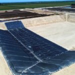
The bottom of a landfill is usually lined with a 1.5-2 mm thick HDPE geomembrane to intercept highly toxic leachate, while the geotextile acts like a layer of “body armor” padded around the geomembrane, effectively preventing sharp gravel or waste from puncturing it. Meanwhile, it allows liquid to pass through but intercepts solid particles, ensuring that leachate collection pipes are not blocked by silt and sand.
Data shows that laying high-quality geotextiles can extend the safety life of the entire anti-seepage system to more than 50 years, serving as the engineering bottom line for protecting groundwater from pollution.
Groundwater Safety & Leachate Management
According to US EPA Subtitle D regulations, the leachate head height at the bottom of the landfill must be limited to 30 cm. In the bottom environment carrying a static pressure of tens of tons of waste per square meter, a non-woven polypropylene (PP) geotextile with a weight between 400 and 600 g/m² is covered on a 1.5 to 2.0 mm thick HDPE geomembrane.
It provides a CBR puncture strength greater than 4500 N, isolating drainage gravel up to 50 mm in diameter above. At the same time, its permeability coefficient greater than 0.001 m/s allows leachate with high suspended solids concentration to quickly flow into the 150 to 200 mm diameter HDPE collection pipes, controlling the probability of liquid seeping into the underlying groundwater aquifer within the permeability standard of 10^-7 cm/s.
Filtration Mechanism
Solid waste at the bottom of the landfill releases a large amount of suspended particles during the early stages of anaerobic degradation. The diameter of silt and clay particles carried in the leachate is usually between 0.002 mm and 0.05 mm. When the flow velocity reaches $1.5 \times 10^{-3}$ cm/s, tiny particles will move downward with the liquid, causing physical clogging in the gravel drainage layer with a porosity of 30% to 40%.
Engineers lay polypropylene non-woven geotextiles between the bottom surface of the waste and the 300 mm thick leachate collection network. Through microscopic physical interception, leachate with a total suspended solids (TSS) concentration as high as 5000 mg/L is filtered, and the effluent TSS is controlled below 200 mg/L.
The parameter for evaluating the filtration performance of geotextiles is the Apparent Opening Size (AOS), determined according to the ASTM D4751 method. This index represents the maximum sieve size on the geotextile that allows 95% of glass beads of a specific diameter to pass through, denoted as $O_{95}$.
- Fine sand formations (particle diameter 0.075-0.425 mm): AOS needs to be ≤0.21 mm (#70 standard sieve).
- Silty loam (particles passing #200 sieve >50%): AOS is between 0.15 mm and 0.25 mm.
- High plasticity clay: Select specifications with an AOS of 0.212 mm or finer.
- Structures with a coefficient of uniformity (Cu) less than 3: Comply with the $O_{95} < C_u \times D_{85}$ retention criterion.
While intercepting particles, the material must maintain the rate at which liquid passes smoothly, measured in engineering by Permittivity (unit $s^{-1}$). According to the ASTM D4491 test specification, this data is determined under constant water pressure with a head difference of 50 mm.
Targeting the high hydraulic load at the bottom of the landfill, the designed permittivity is set between 0.1 $s^{-1}$ and 0.5 $s^{-1}$. Under the long-term action of a vertical static load of 100 kPa, the polymer is compressed, and the porosity of its internal three-dimensional labyrinth structure drops from 85% to about 60%.
Even under pressure, each square meter of geotextile must ensure a liquid flow rate of more than 150 liters per minute. To evaluate long-term filtration efficiency, the laboratory introduces the Gradient Ratio (GR) test (ASTM D5101) to simulate the seepage process from 24 hours to 1000 hours.
Measuring the hydraulic gradient in the 50 mm interval above and below the material, a GR value exceeding 3.0 indicates serious particle accumulation at the filtration interface. Normal GR values stabilize in the range of 1.0 to 1.5, maintaining the bottom head height within the regulatory limit of 30 cm.
Beyond physical particle interception, biofilm growth and chemical precipitation within the leachate system are variables that must be considered in pore size design. Volatile fatty acids (VFA), under the action of methanogens, will generate a biological slime layer with a thickness of 0.5 mm to 2.0 mm.
- Calcium carbonate precipitation: Generated in large quantities when the pH value exceeds 7.5, adhering to the surface of polypropylene fibers.
- Ferrous sulfide (FeS): Iron ions with concentrations exceeding 50 mg/L react with sulfides to crystallize.
- Biochemical Oxygen Demand (BOD5): Waste liquid of 20000 mg/L accelerates the reproduction of aerobic and anaerobic bacteria.
- Dissolved Oxygen (DO) changes: Oxygen concentration gradients cause metal ions to undergo reductive precipitation at the filtration cross-section.
In the face of complex clogging phenomena, theoretical calculations based on $O_{95}$ will produce deviations. Engineers introduce a total clogging Factor of Safety (FS) during the design phase, with values between 3.0 and 5.0. The AOS required for theoretical calculation is enlarged by 1.2 to 1.5 times, or needle-punched non-woven fabrics with a porosity exceeding 90% are used. Materials reaching a thickness of 4.0 mm provide longer internal flow paths, delaying the time it takes for precipitates to block the surface layer.
The US Army Corps of Engineers (USACE) filtration specifications require that the design pore size ($O_{95}$) shall not be less than 2 to 3 times the characteristic grain size ($D_{15}$) of the soil. Combined with a water flow velocity of 0.3 m/s to 0.6 m/s in the collection pipes, physical self-cleaning shear forces are generated.
The Percent Open Area (POA) is determined by optical microscopy, with a POA between 4% and 10% providing a balanced permittivity. The three-dimensional mesh fiber structure of non-woven geotextiles adjusts filtration precision by controlling the Denier of individual fibers.
Using 3 to 6 denier short fibers, through a needle-punching process of 300 to 500 punches per square centimeter, tortuous micro-channels are formed inside the fabric. Liquid flows circuitously within channels 2 mm to 5 mm in length. The long-term flow test (ASTM D1987) simulating the real field stress environment is the evaluation standard for verifying pore size matching. Waste soil samples collected on-site and selected geotextiles are compacted and sealed in a transparent cylindrical permeameter.
Synthetic leachate with actual chemical components is injected, and under a vertical normal pressure of 200 kPa, the system’s permeability changes are continuously monitored for 720 hours (30 days). Material combinations with a permeability coefficient (k) greater than $1 \times 10^{-4}$ cm/s at the end of the test are approved for use in landfill construction.
Cushion Layer Mechanics
Modern municipal solid waste landfills reach depths of 50 to 100 meters, generating vertical static stresses of 500 kPa to 1500 kPa at the bottom base. Beneath a 300 mm thick drainage gravel layer (particle size 19 mm to 50 mm), high-density polyethylene (HDPE) geomembranes with a thickness of 1.5 mm to 2.0 mm face the risk of puncture from physical point loads.
Non-woven needle-punched polypropylene (PP) or polyester (PET) geotextiles, tangled from fibers 4 to 8 denier in thickness, are laid above the HDPE geomembrane. According to the ASTM D5261 test specification, the mass per unit area of polymer fabrics used in engineering applications is distributed between 400 g/m² and 1080 g/m² to absorb and disperse mechanical stresses conducted by angular stones.
US EPA Subtitle D regulations and engineering design standards limit the long-term local tensile strain of HDPE geomembranes to below 0.25%. Without any cushion layer intervention, 38 mm sharp gravel under 500 kPa pressure would cause the membrane to produce more than 3% strain, inducing micro-cracks within 10000 hours.
Engineers use large-scale hydrostatic puncture tests (ASTM D5514) to evaluate the resistance performance of polymer cushions. In an aluminum high-pressure vessel with a diameter of 600 mm, the “membrane-geotextile-gravel” composite structure is exposed to a water pressure of 1000 kPa, undergoing continuous stress-deformation simulation for 100 to 1000 hours.
3D laser scanning data after the test shows that a 540 g/m² geotextile successfully limits the deformation cone depth under 50 mm angular gravel to within 2.0 mm. Local multi-axial tensile strain is strictly controlled within the safe allowable physical range of 0.25%.
- Fiber entanglement density: 300 to 500 needle punches per square centimeter, providing a physical isolation thickness of 3.0 mm to 5.0 mm.
- Load redistribution: Point loads from sharp gravel are effectively dispersed over a base area of 10 to 20 square centimeters.
- Friction angle gain: When combined with textured HDPE geomembranes, it provides an interface friction angle of 22 to 28 degrees.
- Creep resistance: After 50 years of continuous static pressure at 1000 kPa, it still retains more than 60% of its original physical thickness.
During the initial construction phase of landfill cells, 30 to 40-ton CAT 836K waste compactors operate above the primary drainage layer. The anti-slip teeth on their steel wheels generate dynamic ground pressure of 300 kPa to 450 kPa and strong mechanical shear forces at driving speeds of 5 km/h to 10 km/h.
Geotextiles must pass the CBR puncture strength test (ASTM D6241) to resist mechanical damage during construction. The test uses a flat-head steel probe with a diameter of 50 mm, pressed vertically into the fabric at a constant rate of 50 mm per minute, recording the maximum peak force when physical rupture occurs in the material.
| Cushion Weight (ASTM D5261) | CBR Puncture Strength (ASTM D6241) | Grab Tensile Strength (ASTM D4632) | Max Applicable Base Compressive Stress |
|---|---|---|---|
| 400 g/m² (12 oz/yd²) | > 3500 N | > 1400 N | 400 kPa |
| 540 g/m² (16 oz/yd²) | > 4800 N | > 1700 N | 800 kPa |
| 800 g/m² (24 oz/yd²) | > 7000 N | > 2200 N | 1200 kPa |
| 1080 g/m² (32 oz/yd²) | > 9500 N | > 3000 N | 1600 kPa |
Polypropylene (PP) material exhibits extremely high chemical inertness to leachate with pH values between 4.0 and 9.0. Polyester (PET) provides 20% to 30% higher creep resistance under 1000 kPa static pressure, but undergoes alkaline hydrolysis physical degradation when exposed to calcium-rich leachate with pH exceeding 10 for up to 10 years.
Following EPA Method 9090 immersion test specifications, materials are fully immersed in synthetic leachate at 23°C and 50°C for up to 120 days. Qualified PP cushions can retain more than 90% of their initial CBR puncture physical strength in an anaerobic environment containing high concentrations of ammonia nitrogen at 3000 mg/L.
During the installation period, polymer materials are exposed to solar radiation for 2 to 4 weeks. Manufacturing plants add 2% to 3% carbon black or hindered amine light stabilizers (HALS) to the resin masterbatch to ensure the fabric retains 70% of its tensile strength after 500 hours of xenon arc lamp exposure (ASTM D4355).
The nominal thickness measured under an initial pressure of 2 kPa (ASTM D5199) is distributed between 3.0 mm and 7.0 mm. When bearing field waste static pressure of 500 kPa, the three-dimensional mesh structure is compressed by 40% to 60%, maintaining a physical buffer gap of 1.5 mm to 3.0 mm between the gravel and the membrane.
In side slope areas with a gradient of 3:1 (18.4 degrees), the cushion layer determines the geotechnical stability of the overlying soil and waste. Engineers perform physical shear tests (ASTM D5321) using a 300 mm by 300 mm large shear box, applying normal physical stresses of 50 kPa, 100 kPa, and 200 kPa.
- Contact with textured HDPE: Peak friction angle reaches 26° to 30°, with cohesion in the range of 0 to 5 kPa.
- Contact with smooth HDPE: Peak friction angle drops sharply to 10° to 12°, failing to meet the stress balance for a 3:1 slope.
- Contact with drainage gravel: Rough stones interlock with fibers, with the peak friction angle rising to 32° to 35°.
- Post-deformation strength: After 50 mm of physical displacement, 80% to 90% of the peak shear stress is still maintained.
Geotextile rolls with widths of 4.5 to 6.0 meters require physical edge splicing on-site. Operators use high-strength Kevlar or polyester sewing thread, employing double-thread chain stitching (Type 401), with seam strength (ASTM D4632) reaching 60% to 80% of the parent material’s grab tensile strength.
The thermal fusion welding process uses a hot-wedge welder at 400°C to 500°C to melt and bond fibers in the 100 mm to 150 mm overlap area. Seams with a peel resistance greater than 250 N/50mm prevent stones from squeezing into the overlap surface and damaging the bottom membrane when bulldozers spread 300 mm thick drainage gravel.
High-weight cushion geotextiles (800 g/m²) possess an in-plane transmissivity of $2 \times 10^{-4}$ m²/s under 500 kPa compaction. Liquid moves along the plane of the compacted polymer fiber mesh, alleviating local ponding pressure on the geomembrane surface and assisting in reducing the overall hydrostatic head physical height at the bottom.
Leachate Head Control
Federal Regulation 40 CFR Part 258.40 explicitly states that the leachate head height on the bottom liner of a landfill must be limited to 30 cm (12 inches). Physical accumulation of hydrostatic pressure exponentially amplifies the leakage rate of small pinholes in HDPE membranes. When the head increases from 30 cm to 60 cm, the volume of liquid seeping into the groundwater through a manufacturing defect with an area of 1 mm² will increase by 1.4 times.
Maintaining the 30 cm threshold depends on a natural slope design of at least 2% at the bottom base. Under gravity, fluid flows toward the collection ditch at a rate of 0.5 to 1.0 meters per day along a catchment distance of 50 to 100 meters. The base slope, combined with parallel perforated HDPE collection pipes spaced at 30 to 50 meters, constitutes the primary hydrological drainage physical network.
Covering the pipes is a 300 mm thick high-permeability gravel drainage layer with a permeability coefficient (k) greater than $1 \times 10^{-2}$ cm/s. Engineers lay non-woven geotextiles with a weight between 270 g/m² and 400 g/m² between the gravel layer and the overlying waste. The polymer fiber mesh, 2.0 mm to 3.0 mm thick, blocks suspended solids and itself possesses an in-plane transmissivity greater than $3 \times 10^{-3}$ m/s.
In side slope areas with a gradient greater than 3:1 (horizontal:vertical), gravity greatly accelerates the downward flushing of fluid, and the 300 mm thick gravel layer is prone to sliding due to the limitation of the 30 to 35-degree internal friction angle. Engineering designs use composite drainage nets (Geocomposite), where a high-density polyethylene (HDPE) geonet core is thermally bonded to non-woven geotextiles on both sides, as an alternative.
- Net core physical thickness: 5.0 mm to 7.6 mm (based on ASTM D5199 testing).
- Bi-directional tensile strength index: Greater than 15 kN/m.
- Geotextile to net core peel strength: Needs to reach 360 N/m (based on ASTM D7005 testing).
- Normal compressive yield strength: Exceeds 1000 kPa.
- Material carbon black content: 2% to 3% to resist long-term UV degradation.
The testing index for composite drainage materials is Transmissivity (unit m²/s). Testing follows the ASTM D4716 specification, executed in a compacted state simulating a field normal vertical stress of 500 kPa. Liquid passes through the test piece at a hydraulic gradient of 0.1, with transmissivity stabilizing in the range of $1 \times 10^{-3}$ m²/s to $5 \times 10^{-3}$ m²/s, ensuring slope liquid emptying time is less than 24 hours.
Waste stacking of 30 to 50 meters in a landfill applies long-term static pressure up to 500 kPa to 800 kPa on the composite drainage net. Polymer materials undergo compression creep under this load, resulting in an irreversible reduction in net core thickness. Laboratories perform long-term compression creep tests of 10000 hours, deducing that the thickness reduction factor for materials is usually distributed between 1.2 and 1.5.
Leachate gathered at the valley bottom discharges into 150 mm to 250 mm diameter perforated HDPE main pipes covered with geotextiles. The pipes use an SDR 11 rating with a wall thickness exceeding 17 mm to withstand the 30-ton dynamic load from overlying compaction machinery. Intake holes with diameters of 12 mm to 15 mm are distributed alternately on the pipe wall at angles of 120 or 60 degrees.
Head height estimation requires importing hydrological models of extreme weather conditions. HELP (Hydrologic Evaluation of Landfill Performance) software uses data from a 25-year, 24-hour design storm (e.g., 150 mm precipitation) for calculation. Under the peak seepage rate calculated by the model, daily leachate production reaches 20 to 40 cubic meters per hectare, and the pipe fullness must not exceed 75%.
- Initial moisture content of the waste layer: Set at 25% by volume.
- Daily cover layer data: 150 mm thick compacted soil.
- Surface runoff curve number (CN value): Set in the range of 80 to 85.
- Leaf Area Index (LAI): Set to 0 at the beginning of vegetation cover.
Liquid flows along the 1% main pipe slope into the sump at the lowest point. The sump has a bottom area of 2 meters by 2 meters and a sinking depth of 1.5 meters. The interior is filled with coarse pebbles (particle size 50 mm to 100 mm) with a porosity of up to 40%, wrapped in high-permeability non-woven geotextile with an apparent opening size of 0.425 mm (#40 sieve).
Corrosion-resistant stainless steel submersible pumps are installed in the 5 to 10 cubic meter sump. Liquid level sensors transmit head physical parameters to the control room in real-time. When the liquid level in the sump reaches a height of 30 cm, the 3.7 kW to 7.5 kW submersible pump starts. The pumping flow rate is 100 to 300 liters per minute, pumping liquid through high-pressure HDPE double-layer pipes.
During an operation cycle of more than 30 years, high-concentration calcium ions (500 mg/L to 2000 mg/L) and bicarbonates scale within the pipe and geotextile pores. Calcium carbonate precipitation reduces the effective flow cross-section of the pipe by 1% to 2% annually. Operators use high-pressure water jets (10000 psi to 15000 psi) every 1 to 2 years to perform internal pipe cleaning procedures.
- Nozzle physical propulsion speed: 0.2 m/s to 0.5 m/s.
- Cleaning water flow control: 150 to 250 liters per minute.
- Pipe camera inspection (CCTV): 1080p resolution, 300-meter visible distance.
- Pipe network inclination re-measurement: Laser level verifies slope error is less than 0.1%.
Accumulation of landfill gas (methane and carbon dioxide account for about 50% each) forms a gas lock at the bottom, pushing up the local hydraulic head in reverse. The sump is equipped with an independent 150 mm diameter exhaust blind pipe to eliminate the air pressure difference at a rate of extracting 500 to 1000 cubic meters of gas per day, ensuring fluid follows physical fluid mechanics to empty under its own weight.
Protecting the Primary Liner
The primary liner of a landfill usually adopts High-Density Polyethylene (HDPE) geomembrane with a thickness of 1.5 to 2.0 mm (60-80 mil). Under 300-500 kPa static compressive stress generated by waste up to 30 to 50 meters high above the pile, the drainage layer laid on it can easily puncture the membrane body. Using non-woven needle-punched geotextiles with weights of 540-1080 g/m² (16-32 oz/yd²) as a physical protective layer can provide a CBR puncture resistance of over 4000 N.
Resisting Puncture Damage
The leachate drainage system is usually laid directly above the 1.5 mm (60 mil) thick high-density polyethylene (HDPE) membrane. US EPA Subtitle D regulations require the drainage layer to have high permeability. Constructors commonly use natural crushed stone or coarse gravel with particle sizes of 19 to 38 mm (0.75-1.5 inches).
The micro-morphology of natural crushed stone presents multi-angular and irregular sharp facets under a microscope. In some large municipal solid waste (MSW) landfills in California, when the waste pile height reaches 60 meters, the bottom physical pressure exceeds 600 kPa. Huge vertical compressive stress forces irregular gravel tips to penetrate downward into the polymer membrane surface. The physical contact area between a single sharp corner of gravel and the HDPE membrane is often less than 2 mm².
According to physical pressure formula calculations, a 600 kPa uniform load will be converted into local puncture stresses as high as tens of megapascals on a tiny contact surface. After polymer materials exceed the 12% yield tensile strain limit, molecular chains will undergo irreversible physical rupture.
The American Society for Testing and Materials (ASTM) developed the ASTM D5514 large-scale hydrostatic puncture test standard to quantify material parameters. Inside a circular laboratory pressure chamber, anti-seepage membranes, non-woven fabrics of different weights, and standard graded sharp gravel are placed at the bottom. The device gradually increases pressure to 1000 kPa and maintains it for 1000 hours to observe microscopic physical indentations on the material surface.
Test data clearly shows differences in physical protection data among different cushion specifications:
- Unprotected state: 1.5 mm HDPE membrane develops macroscopic perforations under 250 kPa pressure.
- 270 g/m² (8 oz) specification: Indentations up to 0.4 mm deep appear on the membrane surface, with local strain reaching 4%.
- 540 g/m² (16 oz) specification: Maximum indentation depth is reduced to 0.1 mm, with local strain below 0.25%.
- 1080 g/m² (32 oz) specification: Only slight scratches on the membrane surface, with no measurable yield deformation.
High-weight non-woven fabrics’ efficient protection relies on the multi-dimensional physical interlaced structure of polypropylene (PP) or polyester (PET) fibers. In a manufacturing plant, each square inch of polymer mesh undergoes 500 to 2000 high-speed vertical punctures from barbed steel needles. Millions of monofilament fibers with diameters of about 20 to 40 microns are forced to tangle, forming a three-dimensional porous physical network between 3.5 mm and 8.0 mm thick. When gravel tips squeeze downward, the surface polymer fibers first undergo physical displacement and extension.
Displacement of the fiber layer spreads the single-point force originally concentrated on 2 mm² to an area of 15 to 30 cm². Pressure decreases exponentially as the force-bearing area increases manifold. The tensile breaking elongation of polymer monofilaments is usually maintained above 50%, absorbing a large amount of downward mechanical work during deformation.
The ASTM D6241 static puncture test measures specific physical limits for different fabrics absorbing mechanical work:
- A cylinder with a probe diameter of 50 mm is pressed down uniformly at 50 mm/min.
- A 540 g/m² fiber network needs to withstand more than 3100 N of puncture force before breaking.
- The puncture force reading for 800 g/m² material fluctuates between 4800 N and 5200 N.
- Probe displacement yield distance during the test can reach 40 mm to 60 mm.
The designed service life of anti-seepage facilities is set at over 100 years. High-strength fibers immersed in 600 kPa high pressure and complex chemical leachate will undergo creep and thinning of physical thickness. On-site sampling data provided by the Ohio Environmental Protection Agency (OEPA) shows that after 10 years under pressure, the average compression rate of geotextile physical thickness is between 30% and 45%.
Engineering specifications mandatory require introducing a Factor of Safety (FS) of 1.5 to 2.0 in physical calculations. If calculations show 16 oz/yd² material is sufficient to prevent short-term puncture, the drawings will mandate 24 oz/yd² or higher specifications.
On side walls with slope inclinations of 3:1 or 4:1, polymer cushions need to provide specific interface friction angle data. According to ASTM D5321 shear test records, the friction angle between double-sided needle-punched fabrics and textured HDPE membranes is generally between 24 and 28 degrees.
Microbial anaerobic fermentation of bottom leachate is accompanied by the release of a large amount of heat. Data returned from bottom temperature monitoring sensors at several large landfills in New York State shows that local temperatures remain at 45°C to 55°C year-round. Polymers are extremely sensitive to temperature. In a 50°C environment, the tensile yield strength of HDPE membranes decreases by about 25% compared to the standard 20°C laboratory environment.
High-temperature environments have the following numerical impacts on bottom anti-seepage physical performance:
- Puncture tolerance of HDPE membranes is significantly reduced, making them prone to local necking at stress points.
- The softening point of polypropylene (PP) material is around 150°C, with no significant attenuation of physical strength at 55°C.
- Polyester (PET) fibers risk molecular chain hydrolysis in alkaline leachate above 60°C.
- Local laws in some US states strictly limit the use of PET material in environments with pH greater than 9.0.
In extreme conditions where high temperature and high pressure double physical environments overlap, the redundancy of physical buffer space maintains the bottom anti-seepage material within the 12% safe yield strain range.
Preventing ESC
High-Density Polyethylene (HDPE) is polymerized from millions of ethylene molecules, presenting a highly crystalline physical form. At membrane thicknesses of 1.5 mm to 2.0 mm, amorphous polymer chain segments in non-crystalline regions are in a relatively loose state of physical entanglement. When external physical loads continuously act on local gravel contact points of 2 mm², molecular chains in amorphous regions are forced to stretch. Once local tensile strain breaks the material’s 12% yield elongation limit, polymer physical bonds will undergo irreversible slip separation.
US EPA sampling surveys of landfill bottoms in the early 1990s found numerous micro-cracks. High-concentration leachate with a permeability coefficient as high as 10⁻³ cm/s seeps into the underground soil precisely through physical fissures only 10 to 50 microns wide. Pure mechanical stretching takes months to trigger macroscopic fracture in dry laboratory environments.
Surfactants, free fatty acids, and trace volatile organic compounds (VOCs) rich in leachate significantly accelerate the breaking process of polymer chains.
Surfactant molecules invade stretched HDPE amorphous regions, rapidly amplifying local concentrated stresses above 50 MPa, prompting micro-physical holes to develop into penetrating cracks within 24 to 72 hours.
Environmental Stress Cracking (ESC) is a physical degradation phenomenon caused by the joint action of stress and chemical media. ASTM D5397 specifically adopts the Notched Constant Tensile Load (NCTL) test to quantify the anti-cracking life of polymer membranes. The test environment uses 10% Igepal CO-630 solution to simulate extreme chemical leachate. In a 50°C constant temperature water bath, engineers cut a physical notch 0.3 mm deep on a 1.5 mm thick HDPE specimen surface.
After applying a constant tensile load equal to 30% of the material’s yield stress, unqualified resin formulas will undergo physical fracture within 100 hours. Current Pennsylvania solid waste management regulations strictly require that the NCTL test pass time for bottom geomembranes must be greater than 500 hours. Polymers meeting the 500-hour NCTL standard still cannot maintain physical integrity under 600 kPa high pressure and long-term squeeze from sharp gravel. Geotextile intervention completely changes the geometric distribution of physical stress on the bottom anti-seepage layer.
High-weight non-woven fabrics convert downward concentrated point loads from upper gravel into area loads. The following physical parameter comparison shows the specific quantitative impact of stress dispersion on preventing cracking:
- Unprotected gravel contact: Local tensile strain on the 1.5 mm membrane surface is as high as 15% to 22%, far exceeding the 12% safe yield threshold.
- 16 oz/yd² specification protection: Maximum local physical deformation is reduced to 1.8%, with molecular chain segments in amorphous regions within the elastic recovery range.
- 24 oz/yd² specification protection: Maximum local strain measured by instruments is only 0.4%, completely avoiding physical slip risk.
When local strain is controlled below 2% for a long time, HDPE material lacks the physical driving force internally to trigger environmental stress cracking. Even if chemical concentrations in leachate are at extreme values, without micro-physical stretching-produced pores, large molecular groups cannot penetrate into the polymer matrix.
Drilling samples from bottom sections of several large landfills in Florida operating for over 30 years were taken. Laboratory scanning electron microscopy showed that under the protection of 800 g/m² non-woven needle-punched fiber cushions, the underlying 60 mil membrane surface had only subtle physical indentations less than 5 microns deep.
The crystallinity of sampled membranes remained within the factory standard range of 45% to 55%, with no signs of micro-stress cracking deeper than 10 microns observed.
The physical oxidative degradation cycle of polymer anti-seepage materials in anaerobic underground environments is extremely long. The US Landfill Design Manual points out that as long as long-term concentrated compressive stresses are eliminated through a thick physical buffer layer, the physical half-life of materials can reach over 400 years.
Geotextiles thicker than 5 mm also provide a physical barrier layer isolating high-concentration chemical media. The needle-punched interlaced polymer fiber network is filled with pores sized between 70 and 150 microns internally. When leachate permeates downward through the drainage system, suspended fine physical particles are trapped in the fiber network. Accumulated tiny particles and microbial communities form a layer of physical biofilm 1 to 3 mm thick within 6 to 12 months.
The dense biofilm layer significantly reduces the hydraulic permeability of the underlying fiber network. The mobility of leachate trapped between the geotextile and the HDPE membrane tends to stagnate, and dynamic flushing of surfactants on the polymer surface is physically blocked.
- Static contact surface: The thickness of the liquid film adhering to the membrane surface is limited to between 0.1 mm and 0.5 mm.
- Concentration dilution effect: Active chemical molecules in stagnant liquid films are difficult to replenish quickly after consumption.
- Temperature gradient isolation: Polymer fibers and biofilm layers 5 to 8 mm thick lower the temperature of the underlying membrane surface by 3°C to 5°C.
For every 5°C drop in temperature, the thermal motion activity of polymer macromolecules decreases proportionally, and the physical barrier effect of molecular chains against chemical intrusion is significantly enhanced. ASTM D5397 test curves show that when the temperature drops from 50°C to 45°C, the NCTL fracture time of samples can be extended to over 1000 hours.
Soil Separation
According to US EPA Subtitle D regulations, the bottom of a landfill will bear vertical static pressure exceeding 3,000 lbs/sq ft generated by up to 50 to 100 feet of solid waste above. Under such high pressure, fine particles from the bottom clay liner (D50 grain size < 0.075 mm) will be forced into the overlying drainage gravel layer with 40% porosity.
Laying polypropylene non-woven geotextiles with tensile strengths of 100-300 lbs/in can physically block this vertical displacement. It keeps two different graded materials independent, ensuring the drainage system maintains its originally designed permeability coefficient of $1 \times 10^{-2} \text{ cm/s}$.
Physical Interception
According to the US Resource Conservation and Recovery Act (RCRA) Subtitle C / D specifications, waste stacking heights in large landfills are usually between 100 and 250 feet. Huge volumes generate continuous vertical hydrostatic and geostatic pressures of 6,000 to 15,000 pounds per square foot on bottom anti-seepage and collection systems. A drainage layer composed of coarse-grained aggregate is laid above the bottom compacted clay liner (CCL).
Gravel aggregate selected for the drainage layer generally has a diameter between 1.5 and 2.5 inches, with large macroscopic voids remaining inside after stacking. The underlying CCL consists of fine particles passing through a 200-mesh sieve, with individual diameters less than 0.075 mm. Squeezed vertically by thousands of tons of overlying waste, fine clay particles are forced upward into the physical voids of the coarse gravel above.
Laying non-woven needle-punched polypropylene geotextiles between the two strata establishes a thick barrier layer. Industrial-grade geotextiles usually have thicknesses between 80 and 120 mils (2.0 to 3.0 mm). The internal structure is a random three-dimensional network matrix of countless polymer fibers interlaced by mechanical needle-punching.
- CBR Puncture Strength (ASTM D6241): 400 – 800 lbs.
- Apparent Opening Size (ASTM D4751): 0.15 mm – 0.21 mm.
- Grab Tensile Strength (ASTM D4632): 100 – 300 lbs.
- UV Resistance (ASTM D4355): Retains 70% strength after 500 hours exposure.
The Apparent Opening Size (AOS) of engineering materials is precisely matched with the $D_{85}$ value of the underlying soil. $D_{85}$ represents the particle diameter that 85% of the soil sample mass is smaller than. The physical pore sizes formed by interlaced geotextile fibers are strictly calibrated to specifically intercept larger diameter soil particles.
Intercepted larger particles gather above geotextile pores, forming a microscopic physical structure known as Soil Arching. In the region 2 to 5 mm immediately below the geotextile, a large number of blocked particles accumulate into a natural micro-filter cake. Finer particles are subsequently blocked below by the newly formed physical filter cake.
In the early operation of the landfill, heavy crawler compactors repeatedly roll over waste advancement layers about 2 feet thick, generating huge dynamic impact loads. A waste compactor weighing 100,000 pounds has an instantaneous ground contact pressure exceeding 45 psi from its tracks.
The geotextile fiber matrix can absorb and redistribute horizontal shear forces. When subjected to local downward stabbing by irregular gravel from above, the fiber structure undergoes extension deformation. The Elongation at Break of polypropylene non-woven fabrics is in the range of 50% to 70%.
When the material wraps around 1.5-inch rough gravel sharp corners, it adapts to local protrusions through its own tensile strain without penetrating tears. Local tensile deformation maintains the integrity of physical boundaries. Under high-pressure rolling conditions, separation functions do not fail with fiber deformation.
- Vertical load diffusion angle: about 30 to 45 degrees.
- Interface friction angle (soil and geotextile): 22 to 30 degrees.
- Upper limit of aggregate penetration depth: < 0.5 inches.
- Thickness loss under 10,000 psf load: < 30%.
Landfills continue to stack solid waste during operation. Based on the average compaction density of US municipal solid waste (MSW) of 60 lbs/cu ft, when landfill height reaches 100 feet, vertical static pressure on bottom strata will reach 6,000 psf. During heavy compaction machinery operations, such as using sheepsfoot rollers weighing 120,000 lbs, instantaneous dynamic loads will break 10,000 psf.
Under huge gravity, bottom strata of different materials are under extreme pressure. Standard material for drainage layers is usually AASHTO No. 3 or No. 4 graded coarse gravel. Particle diameters are distributed between 1.5 and 2.5 inches, with internal porosity as high as 40% to 45%. If the adjacent bottom layer is a compacted clay liner (CCL), the vast majority of clay particle diameters are less than 0.002 mm.
- Drainage layer gravel: large pores, D50 grain size usually greater than 38 mm
- Clay liner: extremely fine particles, Plasticity Index (PI) greater than 10, moisture content around 15%
- Interface state: abrupt junction between hard large volumes and soft tiny particles
Under pressure, sharp corners of hard coarse gravel above will stab downward into the soft clay surface. Tiny clay particles squeezed by overlying loads will creep and displace upward into the huge voids of gravel along the stress direction. Without a separation layer, huge differences in material grading lead to completely blurred stratum boundaries, and fine particles will fill drainage channels of gravel.
Engineers lay non-woven geotextiles made of polypropylene or polyester between two layers of material for isolation. According to ASTM specifications, geotextiles used for high-pressure isolation need to pass ASTM D4632 grab tensile tests. Tensile strength is usually specified between 200 and 300 pounds, and CBR puncture strength (ASTM D6241) must be greater than 400 pounds.
- Polymer material: 100% virgin polypropylene continuous resin fiber
- Thickness range: usually between 100 and 150 mils
- Elongation: allows 50% deformation buffer before peak force is reached
- Lapping specification: adjacent rolls need to maintain a 12 to 18-inch overlap area during construction
Polymer fibers are interlaced through needle-punching processes to form a complex three-dimensional network structure. Fiber nodes undergo moderate slipping under tensile stress, uniformly dispersing local vertical concentrated loads over areas of dozens of square centimeters. Polymer materials also maintain high chemical inertness in strong acid and alkali leachate environments with pH values from 2 to 13.
Biodegradation exothermic reactions often occur at the bottom of landfills. Polypropylene fibers do not undergo thermal softening in the 140°F heating environment inside landfills. In Interface Friction Angle tests, the friction angle between geotextiles and coarse gravel can usually reach 25 to 30 degrees, ensuring mechanical stability against sliding in slope areas.
Implementation of separation functions depends on the geotextile’s Apparent Opening Size (AOS). Laboratories perform precise testing according to ASTM D4751 standards. By dry sieving glass beads of known diameters, technicians can precisely determine the fabric’s maximum pore size. Engineers select perfectly matched AOS values based on particle distribution curves of underlying soil.
- Test method: Standard dry sieving method with laboratory mechanical shaker
- Standard size: Usually 70 to 100 mesh (corresponding pore sizes of 0.21 mm to 0.15 mm)
- Matching principle: AOS must be less than or equal to the D85 grain size parameter of the soil to be isolated
When the AOS parameter is around 0.15 mm, interlaced geotextile fiber nets allow water molecules and extremely tiny suspended matter to pass. Soil particles larger than 0.15 mm will be blocked on the interlaced mesh. With fluid flushing and pressure, a thin “Filter Cake” will quickly form beneath the geotextile. The filter cake is naturally formed by slightly larger soil particles, with a thickness between 2 and 5 mm.
Once formed, the filter cake in turn blocks finer clay particles from continuing to move upward. Through the self-built filtration mechanism of microscopic particles, the entire stratum structure maintains long-term physical stability under extremely high static pressures above 6,000 psf.
Permeability Maintenance
Precipitation and solid waste decomposition inside landfills continuously generate high-concentration leachate. US EPA Subtitle D federal regulations explicitly state that leachate hydrostatic head height above bottom anti-seepage liners is mandatory limited to 30 cm (12 inches). Drainage networks need to continuously guide toxic fluid into 8-inch inner diameter HDPE perforated main collection pipes at flow rates of 500 to 2,000 gallons per acre per day.
Initial engineering porosity of gravel drainage layers is between 40% and 45%. Without physical barriers, tiny particles from underlying compacted clay (CCL) will accompany moisture migration and static pressures breaking 10,000 psf, seeping upward and filling macroscopic voids of gravel. Mixing in only 15% mass ratio of clay particles will cause the effective porosity of overlying gravel layers to plummet below 15%.
Physical mixing triggers extremely rapid decay of fluid mechanics parameters. Initial Hydraulic Conductivity (K value) of standard 1.5-inch drainage gravel is usually above 0.1 cm/s. After internal voids are filled with clay, overall K values drop logarithmically to low troughs of 0.0001 cm/s or even 0.00001 cm/s.
After fluid physical channels are blocked, large amounts of toxic leachate accumulate in physical blind spots at the bottom of the landfill. Head heights in local areas quickly break the EPA set 30 cm regulatory red line within weeks, greatly increasing hydrostatic pressure on the underlying 60 mil HDPE geomembrane.
Polypropylene non-woven geotextiles provide a layer of filtration media with extremely high vertical Permittivity at clay and gravel interfaces. Laboratory personnel determine, based on ASTM D4491 constant head test standards, that the permittivity of 8 oz/sq yd non-woven geotextile stabilizes between 1.0 and 1.5 sec^-1.
Permittivity test indicators are hundreds of thousands of times higher than underlying compacted clay bases (K < 0.0000001 cm/s). Heavy pressure from 100-foot thick waste causes geotextile thickness to be mechanically compressed by 30%, but its residual physical permittivity can still maintain above the safety threshold of 0.5 sec^-1.
| Fluid Mechanics Test Indicators (ASTM System) | Natural Gravel Layer (Clay Mixed) | PP Geotextile Protection System | Federal Regulation Threshold (EPA) |
|---|---|---|---|
| Vertical Permittivity | Decays to < 0.05 sec^-1 | Stably maintains 0.5 – 1.2 sec^-1 | Test must be > 0.1 sec^-1 |
| Silt Deposit Vol Ratio in Pipes | Accumulates > 40% of pipe dia in 36 months | < 5% within 120 months operation | Must remain free of physical blockage |
| Overall Stratum Permeability (K) | Plummets to 0.0001 cm/s range | Maintains initial 0.1 cm/s level | Long-term maintains > 0.01 cm/s |
Maintaining macroscopic hydraulic parameters stably depends on interception mechanisms of microscopic meshes on suspended particles. Engineers use the Gradient Ratio (GR) in laboratories to calculate anti-clogging efficiency of polymer fabrics. According to ASTM D5101 standards, after 24 hours of continuous pressurized water flushing, GR readings are required to be strictly controlled below 3.0.
Water flows carry extremely fine clay suspended particles through 0.15 mm geotextile physical pores. Slightly larger particles are stuck on polymer fiber surfaces, forming natural filter cakes 2 to 3 mm thick within days.
- Initial flushing phase (0-7 days): Very small amounts of fine suspended soil particles smaller than AOS penetrate the 3D fiber net with fluid.
- Filter cake formation phase (7-30 days): Coarse particles complete physical bridge arching on the fabric surface, with dynamic mechanical adjustment of stratum porosity.
- Long-term operation phase (30 days-50 years): Interface interception efficiency climbs above 99%, with upper and lower head differences tending towards fluid mechanics constants.
Besides dealing with high-pressure physical clogging, extreme biochemical environments at the bottom also test the permeation stability of materials. Biochemical Oxygen Demand (BOD) of MSW leachate is in the high concentration range of 2,000 to 30,000 mg/L.
Large amounts of organic matter breed sticky biofilms 1 to 2 mm thick on filtration contact surfaces. Free calcium and magnesium ions in fluid undergo chemical precipitation under pH 7.5 to 9.0 anaerobic reactions, forming calcium carbonate physical hard scale crystallization on surfaces.
Needle-punched 3D porous structures of non-woven geotextiles possess void volume ratios above 80% at the factory. Biofilms and chemical crystals adhere to single polypropylene fiber surfaces, causing individual fiber physical diameters to swell by 10 to 20 microns.
According to ASTM D1987 long-term bio-clogging simulation test protocols, heavy non-woven fabrics of 16 oz/sq yd continuously immersed in simulated raw landfill leachate for 10,000 hours have absolute permittivity drop by 60%, but terminal values remain at 0.2 sec^-1, meeting engineering acceptance lower limits of > 0.1 sec^-1.
When bearing vertical hydrostatic and geostatic pressures of 10,000 psf, polymer fabrics provide limited in-plane Transmissivity. According to ASTM D4716 test procedures, squashed 2.5 mm geotextiles still retain lateral fluid diversion capabilities of 0.00001 m^2/s internally.
Reducing Material Expenses
According to initial engineering logic of US EPA Subtitle D regulations, without polymer thin layers laid, heavy gravel at the bottom will mix with underlying clay. Landfill benthic structures must add an extra 6 to 12 inches of “sacrificial layer.” 1.5-inch graded gravel as a physical buffer is entirely used to absorb soil particle displacement and does not participate in leachate fluid mechanics cycles. Based on an average loose density of basalt aggregate of 110 lbs/cu ft, total weight of extra stones added on a single acre projected area is as high as 1,200 tons.
In a second phase engineering project of a standard 50-acre landfill unit, sacrificial layers will consume 60,000 tons of natural stone in total. A double-axle dump truck has a single full load weight usually between 20 and 25 tons. To transport 1,200 tons of extra gravel, fleets need to travel 48 to 60 separate trips.
- Single acre truck shifts: Cancel 48 – 60 heavy load transport tasks
- Site traffic density: Peak heavy truck traffic volume drops by 40%
- Dust suppression watering: Decreased by 2 times daily under EPA PM10 indicators
- Carbon footprint performance: Each acre reduces about 1,200 gallons of diesel combustion emissions
In 50-acre site construction, 3,000 extra truck schedules generate huge pressure on site logistics. To level 806 cubic yards of gravel on-site and control it within ±1 inch elevation error, a Caterpillar D6 bulldozer needs to operate at full load continuously for 12 to 15 machine hours. When 10-foot wide six-way dozer blades operate on 3:1 slopes, machine track slip rates increase by 15%. Steel tracks of bulldozers repeatedly roll over compacted clay liners, generating local ground pressure of 8 psi, with physical engineering risks of damaging underlying 60 mil anti-seepage membranes.
Field deployment of polypropylene non-woven geotextiles relies entirely on lightweight manual work. A roll of 15 oz/sq yd heavy non-woven fabric with standard factory dimensions of 15 feet wide and 300 feet long has a total coverage area of 4,500 square feet. Single roll material gross weight is controlled around 470 lbs. A small skid steer loader combined with 4 workers wearing safety equipment can perform unrolling with steel spreading shafts.
- Roll spreading speed: A single group of personnel lays 50,000 square feet in an 8-hour shift
- Seam treatment process: Use high-temperature heat guns or portable sewing machines for 6-inch overlap stitching
- Heavy machinery wear: No need for heavy crawler equipment to level base soil
- Site climate adaptation: Not limited by mandatory operations on muddy base soil surfaces after heavy rain
For every 1 inch reduction in absolute thickness of landfill bottom isolation structures, an extra 1 inch of legal waste landfill volume is gained above. Saving 6 inches of cushion thickness on a 1-acre projected area releases 0.5 Acre-feet of net usable volume in spatial grids.
According to US MSW compaction standards, waste compaction density after modern crawler sheepsfoot roller operations can usually reach 1,200 lbs/cu yd. A 0.5 acre-foot 3D volume equals 806 cubic yards, capable of holding an extra 480 tons of compacted solid waste. In RCRA Class C hazardous waste high-standard landfills, unit cubic yard space allocation is extremely strict. Replacing 6 inches of natural stone with 0.1-inch thick polypropylene thin layers physically extends effective usable depth of pits.
ASTM D1987 fluid mechanics clogging tests show that after 10,000 hours of simulated high-pressure operation, silt deposition in leachate main pipes decreased by 85%. Opening ratios of bottom HDPE corrugated perforated pipes remain at 3% to 5% year-round.
Field maintenance teams do not need to put remote-controlled crawler high-pressure water gun cleaning robots into 8-inch inner diameter drainage pipes for physical dredging every 6 months. Isolation micro-environments established by geotextiles cause obvious physical shifts in lifecycle and maintenance frequencies of entire liquid waste collection networks.
- Pipe cleaning frequency: Dropped from once every half year to once every 36 to 48 months
- Clogging probability: Fine deposits in blind spots of drainage collection networks drop by 85%
- Pipe flow decay: Remains stable based on $1 \times 10^{-2} \text{ cm/s}$
- Equipment wear data: Reduced idling loss of high-pressure cleaning pumps in pH 4.0 strong acid environments
Besides ensuring construction precision for large-scale earthworks, physical isolation layers also provide buffer and cover protection for extremely fragile underlying polymer materials.


Leave a reply