Smooth surface is flat with a friction coefficient of 0.1-0.2, thickness of 0.5-3.0mm, tensile strength ≥25MPa, and elongation at break ≥700%.
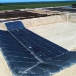
Suitable for anti-seepage on flat ground (such as the bottom layer of landfills, artificial lakes).
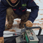
The base layer must be flat during laying (error <2cm), and double-track hot-melt welding is used (temperature 200-300℃, speed 0.5-1.5m/min).
Textured surface is rough (asperity height 0.3-1.0mm) with a friction coefficient of 0.3-0.6, thickness of 1.5-3.0mm (for enhanced anti-slip), and other properties are the same as the smooth surface.
Adapted to scenarios with slope >15° (such as reservoir slopes, mine restoration slopes).
Align the texture direction during laying; the peel test after welding must be ≥30N/mm.
Smooth
Smooth HDPE is significantly superior to textured HDPE in long-term maintenance efficiency.
Its surface roughness is extremely low, allowing high-pressure water guns (usually set at 1500-2000 psi) to quickly wash away silt or chemical crystals.
Cleaning time is usually only 60-70% of that for textured materials of the same area.
During repair work, smooth membranes only require slight grinding to perform extrusion welding.
In contrast, the asperities on the surface of textured geomembranes (height usually >0.25 mm according to GRI-GM13 standards) physically “grab” pollutants, making deep cleaning extremely difficult.
Especially when repairing aging membranes, technicians must first completely smooth the texture layer through mechanical means to expose the flat substrate.
This increases pre-welding pretreatment time by at least 2x and requires extremely high grinding precision.
Cleaning Efficiency
Solid Particles
The surface texture manufacturing processes for geomembranes are mainly divided into two categories:
Co-spray and Structured/Embossed (Nitrogen foaming/Calendering).
Texture Height under GRI-GM13 Standard
Industry standards require a minimum Asperity Height of 0.25 mm for textured geomembranes, but to achieve specific shear strength, actual products are often produced to 0.40 mm to 0.60 mm.
- Particle Size Matching:
- Clay and Silt (particle size < 0.063 mm): These tiny particles easily fill the “valleys” of the textured surface. Once dry, the physical interlocking force is enormous, similar to the plastering effect on concrete surfaces.
- Sand (particle size 0.063 – 2.0 mm): Sand particles get stuck between the texture peaks, forming an abrasive layer. If walked upon or cleaned mechanically, these trapped sand particles become “sandpaper,” causing reverse wear on the geomembrane substrate.
Adhesion Test after Drying
Simulating the difficulty of peeling dried mud in a laboratory environment:
- Smooth Surface Test: The bonding force between the dried mud cake and the smooth HDPE originates mainly from van der Waals forces and is extremely weak. It can be peeled off in sheets using a common scraper applying 5 N of lateral force.
- Textured Surface Test: Mud is embedded inside the texture. During peeling, internal fracture of the mud cake occurs rather than interfacial separation. To completely remove residual soil, a force exceeding 40 N must be applied, usually requiring wire brush assistance, which permanently damages the membrane surface.
High-Pressure Cleaning
Pressure Settings for Cleaning Equipment
- Smooth Cleaning Window: Usually set at 1000 – 1500 psi. The nozzle angle can be maintained at an incline of 30°- 45°, using the cutting force of the water flow to peel off dirt like a shovel. The water flow maintains longer jet integrity on smooth surfaces, and the effective cleaning width per pass is large (about 30-40 cm).
- Textured Cleaning Dilemma: Low-pressure water flow is broken up by the texture structure when passing over a rough surface, causing energy to decay rapidly. To reach the base of the texture, the pressure must be increased to 2500 – 3500 psi, and the nozzle must be perpendicular to the membrane surface (90°) and operate at a very close distance (< 10 cm). This reduces the effective cleaning width per pass to 10-15 cm.
Comparison of Water and Fuel Consumption (per 1000 square meters)
| Consumption Item | Smooth Operation Data | Textured Operation Data | Percentage Increase |
|---|---|---|---|
| Cleaning Water | Approx. 3.5 m³ | Approx. 6.8 m³ | +94% |
| Diesel Consumption (Cleaner) | Approx. 12 L | Approx. 28 L | +133% |
| Labor Hours | 6 hours | 14 hours | +133% |
Microscopic Residue
Biosafety in Aquaculture
In shrimp or fish farming, the pond bottom needs regular disinfection to prevent the growth of pathogens such as Vibrio.
- Biofilm Attachment: Extracellular polymeric substances (EPS) secreted by bacteria are more likely to establish colonies in the recesses of textured geomembranes. The specific surface area provided by the textured surface is more than 3x that of the smooth surface, providing a huge habitat for microorganisms.
- Disinfectant Efficacy: When spraying bleach or hydrogen peroxide for disinfection, the liquid distributes evenly and makes full contact on smooth surfaces. On textured surfaces, the liquid bridging phenomenon caused by surface tension allows pathogens in tiny grooves to escape disinfection, becoming a source of infection for the next season.
Crystalline Anchor Points in Mining and Salt Industries
Crystallization is a common phenomenon in brine evaporation ponds or heap leach pregnant solution ponds.
- Nucleation Sites: Every asperity on a textured surface is an ideal crystal nucleation site. Once calcium sulfate or sodium chloride crystals grow on the texture, they take root deeply like an anchor.
- Descaling Difficulty: Crystalline layers on smooth surfaces usually fall off in large pieces, sliding off under their own weight or with slight vibration. The crystalline layer on a textured surface is mechanically locked and often requires heavy machinery (such as a skid steer loader) with a bucket for physical crushing, which poses a high risk of physical puncture to geomembranes that are only 1.5 mm or 2.0 mm thick.
Due to capillary action, moisture is adsorbed in the texture gaps against gravity on textured surfaces.
Under the same ambient temperature (25°C) and humidity (50%), a smooth surface takes 20 minutes to dry completely, while a textured surface often takes more than 60 minutes and usually requires industrial blowers for forced drying, further increasing energy consumption.
Repair Difficulty
Grinding Depth
Smooth HDPE: Micron-level Abrasion
For smooth materials, the operator only needs to “lightly touch” the surface.
- Target Depth: Remove 10 – 20 microns of the surface layer.
- Visual Feedback: Once the surface gloss disappears and becomes matte, it indicates the oxide layer has been removed.
- Thickness Retention: For a 1.50 mm smooth membrane, the remaining thickness after grinding is usually around 1.48 mm, well within the -10% tolerance allowed by ASTM D5199, without affecting overall mechanical performance.
Textured HDPE: Millimeter-level Cutting
The texture of textured materials consists of irregular asperities and valleys.
According to the GRI-GM13 standard, the asperity height is at least 0.25 mm; in practice, many products reach 0.40 – 0.60 mm to enhance friction.
- Grinding Logic: To obtain a flat welding surface, the grinding depth cannot stop halfway down the “peaks”; it must be ground below the bottom of the lowest “valleys.”
- Actual Cutting Volume: If the texture height is 0.40 mm, the operator must grind off at least 0.45 mm of material to obtain a continuous plane.
- Structural Risk: A standard 1.50 mm single-sided textured geomembrane may have a core thickness of only 1.35 – 1.40 mm (the rest being the texture layer). After deep grinding, the actual effective thickness in the welding area may drop sharply to 0.90 – 1.00 mm. This creates a permanent weak zone at the patch edge, which is very prone to tearing during settlement tension.
| Parameter Indicator | Smooth Grinding | Textured Grinding | Risk Multiple |
|---|---|---|---|
| Single Pass Depth | < 0.05 mm | 0.20 – 0.40 mm | 8x |
| Required Grinding Passes | 1 pass | 3 – 4 passes | 4x |
| Dust Generation | Minimal | Large amount of HDPE particles | High |
| Over-grinding Probability | < 5% | > 60% | 12x |
Tool Wear
Equipment Load and Sanding Disc Consumption
- Smooth: Uses a 4-inch angle grinder with a 100-mesh flap disc. Due to low frictional resistance, one disc can usually handle 50 – 80 standard patch areas. The motor load stays at around 40% of rated power.
- Textured: Coarser 60-mesh or 80-mesh discs must be used, applying greater downward pressure to cut the textured polymer. High friction generates significant heat, causing the resin on the disc to soften quickly and clog the abrasive gaps (glazing effect). A disc often fails after processing 10 – 15 patches. Angle grinders run at 90% or even overload for long periods, significantly increasing the frequency of rotor burnout.
Ergonomics and Fatigue
In on-site construction, repair work often occurs on slopes where operators must stand or hang in unnatural positions.
- Force Feedback: When grinding smooth surfaces, the machine slides smoothly with little reaction force.
- Vibration and Jumping: When grinding textured surfaces, the high-speed rotating wheel hits irregular textures, generating high-frequency vibrations. To prevent the machine from jumping off the path, the operator must hold it tightly with both hands and press down hard.
- Decline in Work Quality: Data shows that after 4 hours of continuous work, the flatness qualification rate for textured grinding drops from 95% to 70% because muscle fatigue prevents the operator from maintaining constant downward pressure, leading to “deep pits” or “missed” areas.
Welding Porosity
Formation of Micro-voids
If the textured surface is not completely leveled, leaving tiny pits (depth may be only 0.1 mm):
- Molten Material Bridging: Extruded molten material has high viscosity; it may flow over the top of a pit without sinking to the bottom to fill it.
- Air Entrapment: Air inside the pit is instantly trapped beneath the weld bead.
- Bubble Expansion: Due to the high temperature (~240°C) of welding, the volume of trapped air expands instantly, attempting to break through the unsolidified weld, forming pinholes or wormholes inside the weld bead.
Vacuum Box Testing Feedback
During the quality control stage, leaks are detected by applying soap solution and drawing a vacuum to 3-5 psi.
- Smooth Failure Mode: Usually due to excessive welding speed or insufficient temperature; bubbles are often large and obvious.
- Textured Failure Mode: A common failure is “slow leakage.” Because residual texture forms a series of tiny interconnected capillaries, gas slowly passes through the contact surface at the bottom of the weld under negative pressure. This leakage is extremely tiny, and bubbles form very slowly; if inspectors do not observe for at least 10 seconds, they are likely to miss it.
Humidity Sensitivity
Moisture Retention Mechanism
- Smooth: Even if wet by rain or morning dew, wiping with an absorbent cloth followed by wind and sun exposure will cause the residual water film to evaporate completely within 5-10 minutes. The surface lacks water-storing structures.
- Textured: The texture structure acts like a sponge. Moisture is locked deep in the texture by capillary forces. Even if the surface feels dry, the base of the texture may still contain moisture. Furthermore, if the area is on a muddy substrate, mud will embed in the texture, making it more than just a water removal issue; the mud must be washed away first before drying, making the process extremely tedious.
Phase Change Explosion during Welding
When 240°C molten material covers a textured surface containing trace moisture (even microgram level), the moisture vaporizes instantly, expanding in volume by more than 1000x.
- Result: A “blowout” phenomenon occurs. High-pressure steam blows through the weld bead, forming visible holes. In textured repairs, the rework rate due to hidden moisture is usually 3x that of smooth surfaces. To avoid this, standard procedures require using a heat gun to preheat and dry the welding path after grinding the textured surface, adding another step and increasing energy consumption.
Visual Inspection
Scratch Depth
According to general industry standards (such as GRI-GM13), the scratch depth on the surface of HDPE geomembranes must not exceed 10% of the nominal thickness of the sheet.
Smooth: Clear Reference Surface
- Measurement Method: Use a micrometer depth gauge.
- Operation Logic: The base of the gauge sits tight against the smooth membrane surface (zero point), and the probe is inserted into the bottom of the scratch. The reading reflects the scratch depth.
- Decision Speed: One measurement takes about 10 seconds. If the reading is 0.18 mm for a 1.5 mm membrane, the calculation is 12%, judged as unqualified, and immediately marked for repair.
Textured: Lack of Reference Surface
- Geometric Paradox: A scratch may span across the “peaks” and “valleys” of the texture. The base of the depth gauge may rest on two peaks (leading to an overestimated reading) or fall into a valley (leading to an underestimated reading).
- Definition of True Thickness: The “thickness” of a textured geomembrane includes the texture height. If a scratch cuts through 0.3 mm of texture asperity but does not damage the core thickness, is it considered damage? This is often a point of contention in the engineering community.
- Field Execution: Due to the inability to measure accurately, CQA engineers are often forced to adopt a conservative strategy: any visible obvious scratch, regardless of depth, is required to be patched. This leads to an “over-repair” rate in textured projects that is more than 30% higher than in smooth ones.
Stress Whitening
HDPE is a semi-crystalline polymer.
When yielding or over-stretching occurs, the crystal structure changes, manifesting macroscopically as the material turning white.
This is an important basis for identifying potential structural damage during installation (such as improper handling or over-tensioning).
| Damage Type | Smooth Appearance | Textured Appearance | Identification Distance |
|---|---|---|---|
| Crease/Dead Fold | Forms a clear white fold line across the entire area. | White lines are interrupted by texture, appearing as discontinuous spots. | Smooth > 5m; Textured < 1m |
| Scuffing | Surface gloss turns matte with slight whitening and clear boundaries. | Only texture tops are flattened; whitening is unobvious and easily mistaken for dust. | Smooth > 3m; Textured < 0.5m |
| Bulge | Light and shadow distortion is obvious, reflecting surroundings like a funhouse mirror. | Diffuse reflection surface produces no distortion; only severe bulges are noticed. | Smooth > 10m; Textured < 3m |
Environmental Overlays
Smooth “Self-cleaning” and High Color Contrast
- Wind Cleaning: Dry dust is hard to attach to smooth surfaces; a level 3-4 wind can blow away most floating dust, restoring visibility of the black surface.
- Rain Cleaning: A light rain can wash away mud and soil.
- Fingerprint Test: Even if there is dust, an inspector wiping with a glove immediately reveals a clear black background. Any damage is unmistakable under the black-and-white contrast.
Textured “Dust Trap” and Blind Spots
- Filling Effect: Dust fills the recesses of the texture. If there is a pinhole, dust will fill it too.
- Color Uniformization: The entire membrane surface turns earthy gray. Since the inside of a pinhole is also earthy (filled with soil), it is color-consistent with the surrounding texture.
- Irreversible Masking: Once the texture is packed with mud, it cannot be removed by simple sweeping unless high-pressure water is used. Visual acceptance in this state is virtually ineffective. Data shows that in dusty environments, the initial leak detection rate for textured geomembranes is usually below 40%. Many leaks can only be found by subsequent dipole methods or after being put into use.
UAV and AI
With the increase in large-scale landfill projects, the trend is to use drones equipped with high-resolution cameras for inspection.
Smooth: Ideal Dataset for AI Algorithms
- Feature Extraction: Computer vision algorithms (such as CNN) easily extract defect features on smooth surfaces. White scratches or hole edges on a black background are extremely sharp.
- False Positives: Extremely low. Except for occasional water reflections, there are almost no interference items.
- Detection Precision: At a 50-meter flight height with 1 cm/pixel resolution, AI can identify damage of about 2 cm.
Textured: Algorithm’s Nightmare
- Feature Confusion: Random shadows produced by texture are very similar to real damage at the pixel level.
- Data Processing: To reduce noise, the algorithm must increase the filter threshold, leading to many “false negatives.” Alternatively, lowering the threshold results in thousands of “suspected points” being marked, requiring engineers to spend days manually reviewing photos, completely offsetting the efficiency gains of drones.
- Current Status: Currently, mainstream geomembrane AI detection systems have an accuracy of 95% for smooth membranes, while for textured ones, it is hard to exceed 70%.
Under natural lighting, an inspector can identify a 1.0 mm diameter puncture on a smooth surface from a distance of 1.5 meters.
In contrast, the diffuse reflection and complex shadowing effect of textured geomembranes generate huge visual noise, reducing defect identification rates by 40% to 60%.
For textured materials, the same 1.0 mm puncture is often hidden in a 0.5 mm texture valley.
An inspector must shorten the observation distance to 0.3 meters and use low-angle side lighting to barely identify it, causing the coverage efficiency of manual inspection to drop from 2000 m²/hr (smooth) to 800 m²/hr.
Textured
Textured HDPE geomembranes physically change the surface morphology, mainly used to enhance the interfacial shear strength of the material.
According to the GRI-GM13 standard, the asperity height is usually required to reach 0.25mm or above 0.40mm.
This irregular texture can significantly increase the friction between the geomembrane and contact materials (such as geotextiles, soil, or concrete), raising the interfacial friction angle from about 8°-12° (smooth) to 22°-35° (depending on the contact medium).
This physical property allows it to adapt to steep slopes of 3:1 or even 2.5:1, preventing the cover soil or liner system from sliding under gravity.
Friction Angle and Shear Strength
ASTM D5321
ASTM D5321 is currently the globally recognized standard for direct shear testing of geosynthetic interfaces.
- Shear Box Size:
Unlike small shear testers for soil, large shear boxes (usually minimum 300mm x 300mm) must be used for textured geomembranes. This is to eliminate scale effects and ensure the test area contains enough texture distribution to represent real large-scale laying conditions. - Strain Rate:
- Peak Strength Test: Usually adopts a displacement rate of 1.0 mm/min.
- Residual Strength Test: May adopt a slower rate to prevent data distortion due to frictional heat or pore water pressure buildup.
- Application of Normal Stress:
The laboratory must simulate real loading on site.- Closure Projects: Cover soil is thin; normal stress is usually between 10 kPa and 50 kPa.
- Landfill Bottom Liners: Waste stacks are massive; test stress may reach 500 kPa to 1000 kPa.
Note: The friction angle is not a constant; it changes non-linearly with increasing normal stress (usually decreasing slightly at high stress). Therefore, multi-point testing within the design load range is necessary.
Typical Interface Friction Angle Data Ranges
The following data is based on third-party laboratory test results for co-extruded textured HDPE geomembranes.
| Interface Combination | Typical Peak Angle | Typical Residual Angle | Physical Mechanism Notes |
|---|---|---|---|
| Textured HDPE / Needle-punched Non-woven Geotextile | 26° – 34° | 18° – 24° | Strong interlocking between fibers and texture. After large displacement, fibers are broken or flattened, and strength drops significantly. |
| Textured HDPE / Compacted Clay (CL) | 20° – 26° | 14° – 20° | Depends on clay moisture content and compaction. Overly wet clay forms a lubrication film, reducing strength. |
| Textured HDPE / Sandy Soil (SP/SW) | 30° – 36° | 28° – 34° | Sand grains embed in texture gaps, forming high sliding resistance with less residual strength decay. |
| Textured HDPE / Geonet | 20° – 25° | 18° – 22° | Hard-to-hard contact; friction comes from rough interlocking, heavily influenced by temperature. |
| Textured HDPE / Woven Geotextile | 18° – 24° | 12° – 16° | Woven fabric surface is smoother; interlocking effect is weaker than non-woven. |
Peak Strength vs. Residual Strength
1. Stress-Displacement Curve Characteristics
In ASTM D5321 testing, as shear displacement increases, shear stress usually rises to a highest point (peak) and then decreases as displacement continues, finally stabilizing at a lower level (residual value).
- Peak Point: Usually occurs at 5mm to 20mm displacement.
- Residual Point: Usually occurs after displacement exceeds 50mm to 100mm.
2. Reasons for Strength Decay
At the peak point, geotextile fibers are tightly hooked;
As displacement continues, fibers are broken, pulled out, or laid down in the shear direction.
The original “Velcro” effect fails, transitioning to friction between polished surfaces, causing a significant drop in strength.
3. Design Principles
- Conservative Design (High-risk areas): Such as landfills containing hazardous waste or mine facilities near residential areas, usually mandate using residual strength for design. This assumes the slope has already undergone some creep or sliding, and the system must remain stable. This is very safe but often requires gentler slopes (e.g., 4:1), increasing footprint and earthwork.
- Routine Design: If it can be ensured that no pre-tension is generated during installation and operational displacement is strictly controlled, peak strength can be used, but a higher threshold for Factor of Safety (FS) is set (e.g., FS > 1.5 instead of 1.3).
Asperity Height
The GRI-GM13 standard specifies a minimum texture height of 0.25mm (for membranes over 1.0mm thick).
In practical application, increasing texture height usually improves friction performance:
- 0.25mm Texture: Suitable for general slopes (slope < 3.5:1).
- 0.40mm – 0.50mm Texture: Often called “High Texture” or “Power Texture.” Designed specifically for steep slopes (2.5:1 or 3:1).
Studies show that for every 0.1mm increase in texture height, the interface friction angle with non-woven geotextile may increase by 1° to 3°.
However, when in contact with compacted clay, excessively high texture might not continuously increase friction because the limiting factor becomes the internal shear strength of the clay itself (cohesion $c$ and internal friction angle $\phi$).
If interfacial friction exceeds the internal strength of the clay, the failure plane will shift from the interface to the interior of the clay layer.
GRI-GM13 Standard
Thickness Definition
1. Nominal Thickness
This is the thickness specified on the order contract (e.g., 1.5mm or 2.0mm).
For smooth surfaces, this is the measured value;
for textured ones, it usually refers to the setting during mold extrusion or the calculated total volume including texture.
2. Minimum Average Core Thickness
This is the most decisive parameter in GRI-GM13.
- Definition: The thickness of the solid HDPE substrate after removing surface texture asperities.
- Measurement Method (ASTM D5994): Use a specific tapered probe micrometer, where the probe tip falls into the texture “valley,” or measure the cross-section via optical microscope.
- Standard Requirement: Must reach 95% of the nominal thickness minus design tolerance. For example, if a nominal 1.5mm textured membrane has a core thickness below 1.425mm, it is considered unqualified.
- Engineering Significance: The core thickness bears the main task of liquid barrier and tension resistance. If substrate thickness is sacrificed to increase surface roughness, puncture and tear resistance will plummet.
3. Asperity Height
- Standard Requirement: $>0.25 \text{ mm}$ (GRI-GM13).
- Extreme Effects: Excessive texture increases friction but if achieved via “spray” processes, the bonding between particles and base may be weak; if via co-extrusion, deep texture might cause local core thickness to be too thin, forming weak points.
Subtle Differences in Tear and Puncture Resistance
| Performance Indicator (ASTM Standard) | Physical Mechanism | Textured vs. Smooth (GRI-GM13) |
|---|---|---|
| Puncture Strength (ASTM D4833) | Simulates force required for a probe to penetrate the membrane. | Values are usually the same. E.g., both require >400N for 1.5mm. Surface texture has minimal effect on the probe; the test mainly measures resin hardness and core thickness. |
| Tear Strength (ASTM D1004) | Simulates resistance to propagation after a sharp notch is stressed. | Values are usually the same. E.g., both require 187N for 1.5mm. As long as the core thickness is standard and the resin is not degraded, tear resistance should be equal. |
While standard values are the same, the actual test curve for textured samples usually has much higher standard deviation than smooth ones.
This is because whether the test probe or tear path passes through a “peak” or “valley” has a 5-10% random impact on the individual reading.
Carbon Black Content
- Standard Indicator: Carbon black content 2.0% – 3.0%.
- Challenges for Textured: In co-extrusion, the surface texture layer often uses foaming agents (like Nitrogen) to create the rough effect. Bubbles can displace carbon black particles. Under a microscope, the carbon black density at the tips of texture might be lower than inside the substrate.
- Consequences: Texture tips are the first line of defense against UV rays. If carbon black encapsulation is insufficient, tips will age first, leading to “powdering” or texture flattening, eventually losing the designed friction angle after several years. GRI-GM13 emphasizes that dispersion tests must cover the surface area.
In landfill or stockpile design, soil displacement of more than 10% usually means the slope has already failed.
In other words, before the geomembrane is stretched to 700% breakage, the entire geotechnical structure is already destroyed.
Therefore, having 700% elongation at break is “performance overflow,” whereas 100% is more than enough to handle uneven settlement (usually <5%).
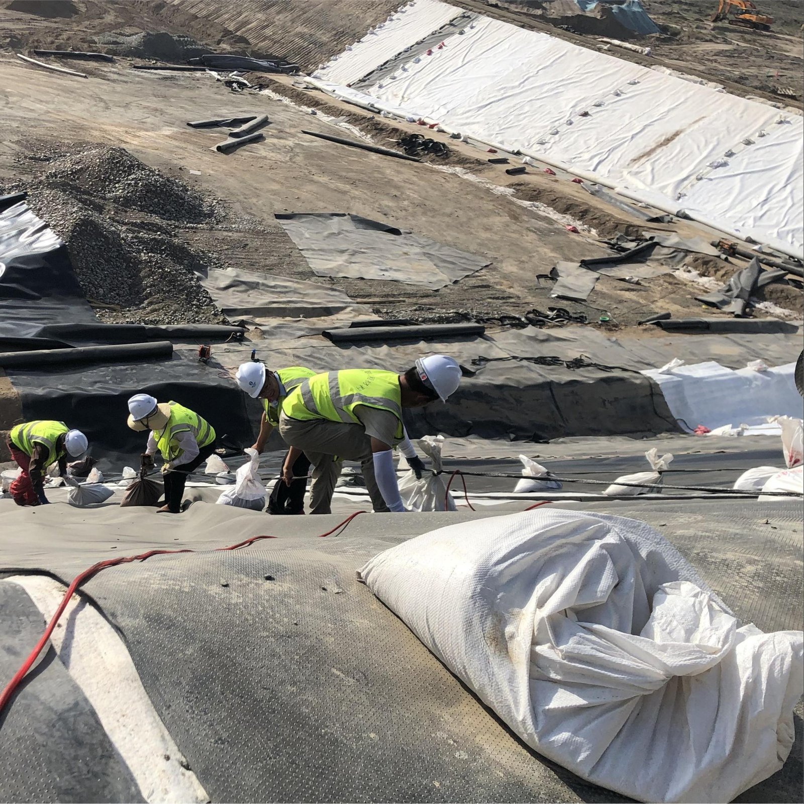
Application and Installation
Typical Engineering Applications
1. Landfill Capping
- Condition: Landfills are often dozens of meters high, with side slope designs at 3:1 (18.4°) or 4:1 (14.0°). Closure requires laying 60cm – 100cm of vegetation soil over the membrane.
- Physical Requirement: The friction angle between smooth HDPE and geotextile/soil is about 11°. If smooth is used, $\tan(11^\circ) < \tan(18.4^\circ)$, and the cover soil will inevitably slide during heavy rain saturation. The 28° – 32° friction angle provided by textured geomembrane is the only physical support maintaining veneer stability.
2. Landfill and Tailings Side Slope Liner
- Condition: Side walls of new cells, usually paved with composite liner systems (GCL + HDPE).
- Double-sided Textured Application: Usually uses Double-Sided Textured here.
- Bottom Surface: Interlocks with GCL or compacted clay to prevent the membrane itself from sliding down the slope.
- Top Surface: Provides enough friction to allow heavy equipment (like bulldozers) to work safely on the slope when laying gravel drainage layers.
3. Heap Leach Pads
- Condition: Ore stacks in copper or gold mines can reach 60m – 150m. Bottom liners bear massive normal stress.
- Special Need: Under high pressure, smooth membranes are prone to displacement due to uneven settlement. Textured geomembranes lock the stack and protect collection pipe systems from shearing.
4. Concrete Embedment and Connection
- Condition: Geomembranes need to connect to concrete structures (like intake towers, channels).
- Mechanical Anchoring: Texture significantly increases the grip between polyethylene and the concrete pouring interface, providing extra water-stop and pull-out security when using E-Lock or mechanical battens.
Welding Pre-treatment
1. Necessity of Grinding
If surface asperities enter the welder, it leads to:
- Uneven Heat Transfer: The wedge cannot fully contact the membrane, leaving recesses underheated.
- Porosity Channels: Asperities prevent the two layers from being pressed completely together, leaving tiny leak channels and causing air pressure test failure.
2. Operational Specifications
- Tools: Use low-speed angle grinders equipped with wire brush wheels or sanding discs.
- Area: Along the overlap edge, grinding width is usually 100mm – 150mm (covering the entire weld zone).
- Depth Control: This is a delicate operation. The goal is to only level the peaks to make them smooth, without damaging the HDPE core thickness.
- Tolerance: Grinding depth must not exceed 10% of the nominal thickness. If a 1.5mm membrane is ground down to 1.2mm, that area must be scrapped and patched.
- Cleaning: Grinding generates a lot of HDPE dust. Dust must be removed with clean cotton yarn before welding, or it will carbonize in the weld or form a barrier, leading to zero peel strength.
Hot Wedge Welding
Physical properties of textured geomembranes require technicians to recalibrate automatic welders (like Leister Astro or Demtech Pro-Wedge).
| Parameter | Smooth HDPE Reference | Textured HDPE Reference | Physical Reason |
|---|---|---|---|
| Speed | 2.5 – 4.0 m/min | 1.5 – 2.5 m/min | Textured surfaces have more area and different heat absorption after grinding, requiring longer dwell time to reach molten state. |
| Wedge Temperature | 320°C – 380°C | 350°C – 420°C | Compensates for heat loss due to increased contact thermal resistance of rough surfaces. |
| Nip Pressure | 600 – 800 N | 800 – 1100 N | Greater physical pressure is needed to flatten residual micro-texture and force molten PE to fill gaps. |
| Roller Material | Silicone or Steel | Steel or Hard Textured | Textured surface acts like sandpaper, quickly wearing down soft silicone rollers. |
Extrusion Welding
- Grinding Range: Must grind away all texture within 10mm – 20mm beyond the welding zone. Molten rod cannot achieve molecular fusion with unground textured surfaces; welding on unground surfaces leads to “cold welds” that peel easily.
- Hot Air Pre-heating: Because textured membranes are usually “thicker” (considering texture volume), pre-heat air needs higher temperature or volume to ensure substrate surface reaches 85°C – 100°C before coverage.
Textured HDPE geomembrane is a specialized material for geotechnical engineering involving slopes steeper than 4:1 or high interfacial shear stress.
In landfill final cover systems, it prevents cover soil from sliding on 3:1 slopes;
At the bottom of heap leach pads, it locks the stack under normal stresses as high as 1000 kPa.
The technical threshold for installing textured membranes is significantly higher than for smooth ones, with the core difference being the edge grinding process before welding.
To eliminate interference with wedge weld airtightness, installers must use angle grinders to remove 100mm – 150mm of texture in the overlap zone while ensuring core thickness reduction is under 10%, and reducing welder speed to 70% – 80% of smooth conditions to ensure full fusion.