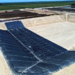

Maintain a heap leach pad liner by controlling damage above the membrane, reviewing leakage and drainage trends, and inspecting exposed details before defects become concealed. Inspection frequencies and response levels must follow the facility’s approved operating plan, design and permit. A fixed inspection count, universal leakage limit or material warranty cannot replace that plan.
This article focuses on operation and maintenance. Use the separate heap leach liner testing guide for construction acceptance, seam tests and repair closeout. Do not treat destructive construction sampling as a routine maintenance requirement for every operating liner.
Strategy 1: Proper Overliner Management
Manage the complete protection system
The overliner is the material placed above the geomembrane, often performing protection and drainage functions. Its grading, particle shape, placement method, thickness and interaction with any geotextile matter together. A thicker membrane or heavier fabric does not automatically make angular rock, unsuitable subgrade or uncontrolled equipment traffic acceptable.
Before a new material source or placement method is used, review its compatibility with the approved design. Check fines content and drainage performance as well as puncture risk. Sharp particles, segregation, oversize fragments and local thin cover can create conditions that were not represented in the original assessment.
GRI-GS11 provides a method for site- and product-specific test pads used to assess puncture protection. A representative trial can help assess the proposed materials and construction operation. It is not a generic approval of a particular GSM or aggregate size.

Separate average loading from local puncture risk
A simple screening calculation for vertical stress from a uniform heap is unit weight multiplied by height. For an illustrative unit weight of 20 kN/m³ and a height of 30 m:
Nominal vertical stress = γ × H = 20 kN/m³ × 30 m = 600 kPa.
This simplified value excludes localized particle contacts, equipment effects, geometry and detailed stress distribution. It is not an allowable membrane pressure or a stability calculation. In particular, a shallow-fill pressure estimate must not be presented as representative of every deep heap. The designer should assess the actual load cases and drainage conditions.
ASTM D5514/D5514M-24 includes performance tests using site-selected subgrade materials under hydrostatic compression. Specify the relevant materials, pressure, temperature and duration when asking a laboratory to assess the protection system; do not compare a small index puncture result directly with field pressure in kPa.
Control placement and traffic
- Record the accepted layer arrangement, material source and placement limits before work starts.
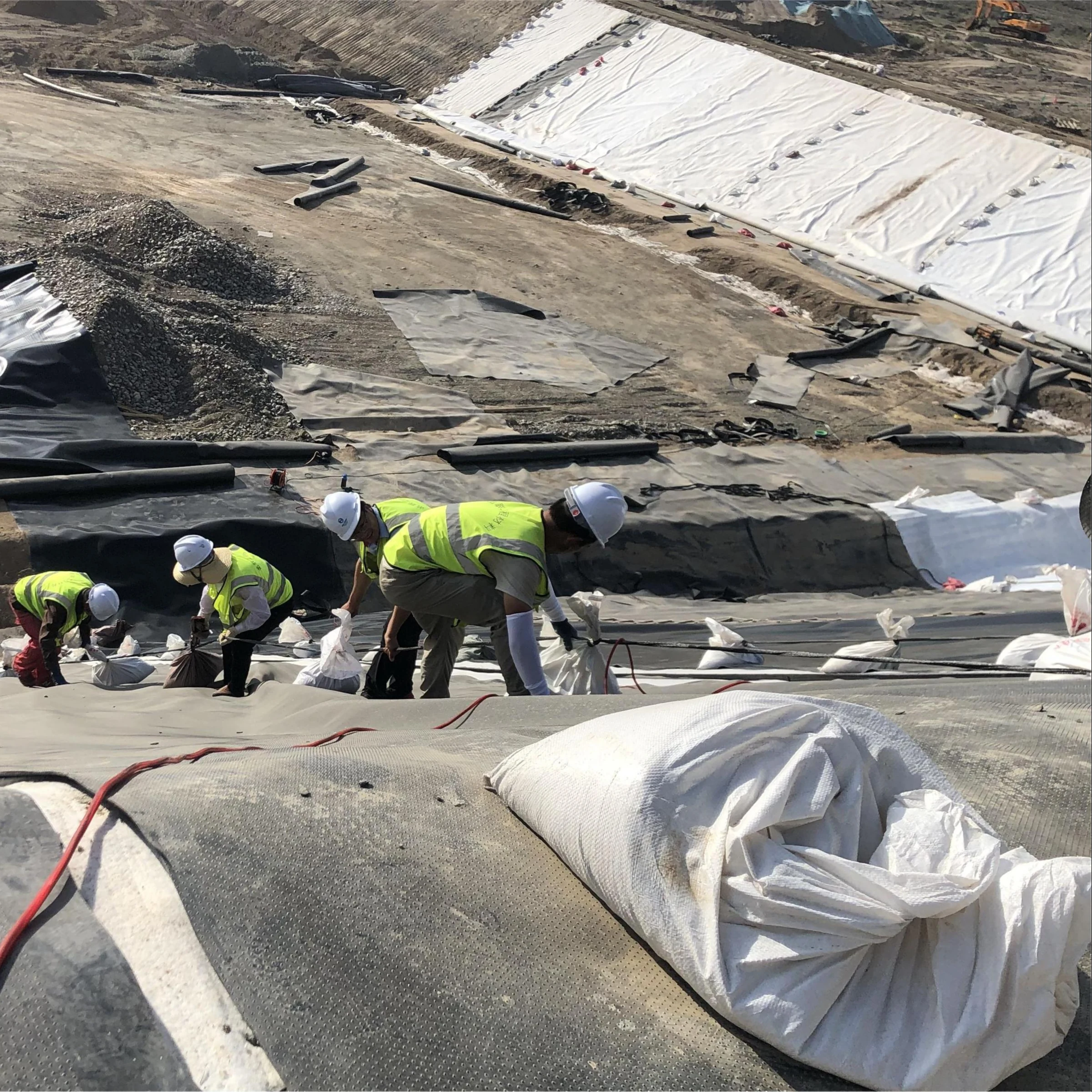
- Keep equipment off exposed geomembrane. Establish approved routes and adequate protective cover before loading; turning, braking and repeated passes require particular attention.
- Observe initial spreading for dragged fabric, displaced protection, bridging, wrinkles and concentrated loading. Stop the affected operation when damage or an unapproved condition is found.
- Maintain inspection hold points before the next layer hides the work. Retain photographs and sector references so later concerns can be located.
- Reassess protection if the aggregate source, vehicle, load, lift arrangement or construction sequence changes.
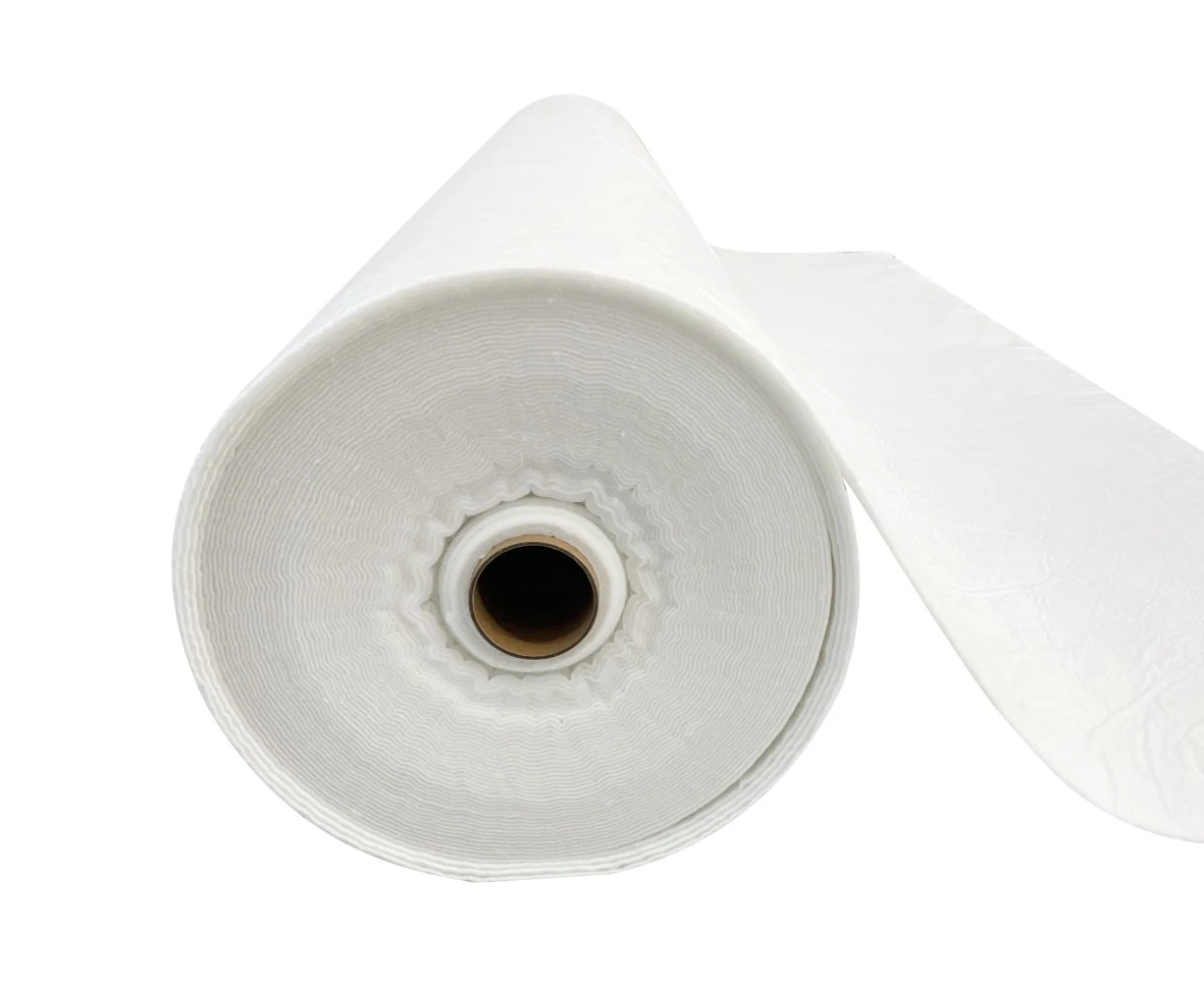
Use the designer’s approved cover thickness, gradation and equipment restrictions. There is no single 300–500 mm cover or universal maximum stone size that can be recommended for all heap leach pads without knowing the system. For a new nonwoven protection geotextile, compare relevant test results and system performance rather than replacing it solely by mass per unit area.
Strategy 2: Monitor Leak Detection and Recovery
Define what the measurement represents
In a double-liner system, the leak detection and recovery system may collect liquid between the primary and secondary barriers. Define the instrument, collection zone and reporting units explicitly. “LDR” can be used inconsistently; a flow reading, a normalized leakage rate and the physical drainage system are different things. A single-liner facility may not have this interliner measurement at all.
Review the measured flow together with operating conditions, liquid head, rainfall, construction history and instrument performance. Increased flow deserves investigation but does not by itself locate a hole. A low reading also does not prove liner integrity if a drain, pump, sensor or meter is not functioning correctly.
Normalize measurements without hiding the raw data
Keep raw volume and measurement period in the log. Where the operating plan requires a rate per area:
Normalized rate (L/ha/day) = collected volume (L) ÷ elapsed days ÷ contributing lined area (ha).
For example, an illustrative collection of 600 L over 24 hours from a defined 2 ha zone is 300 L/ha/day. The same 600 L over 12 hours is 600 L/ha/day. Neither value is an acceptance limit. Use the correctly defined contributing area and the approved action levels; comparing rates calculated from different areas can mislead the reviewer.
If the meter records pump discharge rather than continuous inflow, consider changes in sump storage and pumping periods before interpreting the value. Log outages, calibration checks, maintenance and any estimated readings. Preserve the raw records rather than smoothing away sudden increases.
| Observation | Checks to make | Record or response |
|---|---|---|
| Sudden increase in flow | Meter operation, recent rainfall, liquid head, loading changes and construction activity. | Time, volume, zone and operating conditions; notify the designated reviewer under the response plan. |
| Persistent upward trend | Compare consistent periods and contributing areas; review drainage and water-balance records. | Document the trend and investigation; apply approved alert and action levels. |
| Unexpectedly low or zero reading | Pump, sensor, power supply, collection path and possible blockage. | Distinguish a verified low flow from a missing or invalid measurement. |
| Threshold exceeded | Validate the reading without delaying required notification or protective action. | Follow the approved trigger-action-response plan and permit obligations. |
Investigate and close out anomalies
Assign a responsible person and a response deadline under the operating plan. Define when the engineer must review the condition, when operations in an affected area must be restricted and which approvals are needed before restarting. Do not improvise a chemical dosing change, emergency pumping arrangement or excavation on the basis of a generic maintenance article.
Electrical leak location can be useful where the barrier remains accessible and the configuration supports it. ASTM D6747-25 addresses method selection; ASTM D7007-24 covers water- or earth-covered geomembranes. Neither means that a routine surface survey can reliably locate every defect underneath an operating heap. Review access, electrical continuity, cover and safe repair feasibility with the specialist.
Strategy 3: Protection for Exposed Areas
Inspect transitions, edges and service access
Exposed perimeter strips, pond connections, pipe penetrations, anchor zones and transitions deserve their own inspection map. Look for displaced ballast, erosion, unsupported spans, settlement, damaged welds, sharp debris and abrasion. Heat-related wrinkles need assessment in relation to temperature, restraint and loading; do not cut or stretch the sheet simply to make it look flat.
Access controls should protect the liner during routine maintenance by other trades. Establish designated walkways and equipment routes, prevent dragging hoses or tools over vulnerable details, and inspect the affected area after intrusive work. A geotextile cover alone is not permission for unrestricted vehicle traffic.
Use event-based checks as well as the routine schedule
The approved plan should state who inspects, which areas are accessible, how often routine checks occur and which events trigger additional checks. Useful triggers include storms, significant wind, unusual settlement, new loading, nearby maintenance and changes in leak detection trends. The appropriate frequency depends on consequences and operating conditions; “three inspections per shift” is not a universal ASTM requirement.
| Trigger | Focus | Closeout evidence |
|---|---|---|
| Before new cover or loading | Accepted liner, protection continuity, material and traffic route. | Sector release, photographs and responsible reviewer. |
| After strong wind or heavy rainfall | Edges, anchors, erosion, displaced protection and drainage paths. | Mapped observations, corrective work and reinspection. |
| After work near the liner | Tool damage, disturbed penetrations, temporary supports and debris. | Work-area handback and any repair test results. |
| Leakage or settlement anomaly | Relevant collection zone, instruments and affected details. | Investigation, approved response and evidence for return to service. |
Make repair records usable at the next inspection
Give each defect a unique ID tied to a plan location. Record a context photograph, a close-up, measured dimensions, the observation date and relevant operating conditions. Keep the original observation when a repair is added; do not replace it with a final photograph and lose the history.
Qualified personnel should assess the damaged area and implement the approved compatible repair. Record the material, welding procedure, applicable continuity or strength checks, reviewer and release date. A cosmetic patch is not a completed repair until the required verification has passed. Repeated defects at one location call for review of the underlying load, support or movement, not endless patching.
Keep a practical maintenance register
Use one register linking sector, inspection trigger, reading or defect, immediate action, owner, due date, verification and status. Retain as-built plans, original CQA records, instrument records and repair histories together. This lets the team distinguish installation damage, later traffic damage, changing operating conditions and instrumentation faults.
For replacement material or an expansion, review heap leach liner selection and provide Jinseed with the existing specification, chemical exposure, temperature, thickness and required documentation. Request a material and documentation review; operating acceptance remains with the authorized project team.