Subgrade work should be carried out with a compaction level of at least 93%, using crushed stone in the 20–40 mm range. Each layer should be compacted at a thickness of no more than 15 cm, with moisture content controlled within ±2%. Installing 200 g/m² geotextile together with a drainage slope of at least 2% can reduce settlement by about 30%.
Subgrade Preparation
Clearing and Excavation
The topsoil contains up to 15% fallen leaves and decayed vegetation, giving it a loose, sponge-like structure. Remove the upper 15 to 25 cm of soil with an excavator until firm yellow-brown subsoil is exposed. A 1.5 to 2 ton mini crawler excavator is ideal for this work. Fitted with a 400 mm wide grading bucket, it applies only about 30 kPa of ground pressure, which helps protect the intact bearing layer below.
Grass roots spread 60 to 90 cm laterally underground and penetrate about 20 cm deep. Workers should cut the fibrous roots by hand with spades, then remove the turf in 30 × 30 cm sections.
- Cut any main root thicker than 12 mm
- Excavate the soil within 15 cm around each main root
- Backfill with 30 mm crushed stone
- Spray an environmentally friendly root inhibitor at 5% concentration
Any large hardwood roots left underground will rot into sludge within 12 to 18 months. Once a tree root 5 cm in diameter has fully decomposed, it leaves behind a void with a cross-sectional area of about 20 cm².
The gravel layer placed above may weigh more than 400 kg/m². Under that load, hidden voids in the subsoil can collapse and cause sudden surface settlement of 8 to 12 cm.
Use a portable soil tester to check the exposed yellow-brown subsoil at several points. Readings should remain stable between 2.5 and 3.0 kg/cm². If a handful of soil can be squeezed into a ball and, when dropped from 1 meter onto concrete, breaks naturally into 4 to 6 pieces, the moisture content is around 12% to 18%, which is ideal for construction.
- Remove all sharp stones larger than 8 mm
- Sweep away glass fragments longer than 20 mm
- Fill depressions deeper than 15 mm
- Extend cleaning at least 30 cm beyond the construction boundary
Quartz and flint fragments may be buried in the soil. Under a static pressure of 20 kg/cm², the sharp edges of these very hard stones can easily puncture 0.8 mm waterproofing material.
Workers should screen the surface soil through 10 × 10 mm wire mesh. Hard debris is discarded, while the remaining 2 to 5 mm fine sand and clay are left in place as a smooth cushioning layer.
If buried red brick or waste concrete is found, excavate an additional 45 cm. Construction debris of this kind absorbs water like a sponge and expands and contracts significantly as temperatures fluctuate between -5°C and 30°C.
Surveyors should use GPS equipment to check elevations at 5 meter intervals. Across the entire site, the finished level tolerance must be held within ±10 mm, with no wave-like undulations.
Perimeter anchor trenches should be excavated on the same day in accordance with the design drawings. A U-shaped trench 20 cm deep and 15 cm wide should be formed, with side slopes trimmed to a natural angle of 40 to 45 degrees to prevent collapse.
- Remove 50 cm of soft mud
- Backfill with a 1:3 sand-and-gravel mixture
- Lay two layers of 150 g non-woven fabric
- Observe groundwater level for 72 hours
If groundwater continues to seep in at 20 cm excavation depth, with inflow reaching 0.5 m³/h, install a submersible pump with a 15 meter head and 10 m³/h capacity for continuous pumping.
After water has been removed, excavate a further 30 cm in the wettest areas and replace it with permeable material. Lay a 15 cm thick hidden drainage layer using clean pebbles in the 40 to 60 mm range.
The exposed subgrade must be covered within 48 hours. If left under strong sun or exposed to rainfall, the upper 3 to 5 cm will either turn to slurry or dry out and crack, reducing load-bearing capacity by as much as 40%.
Cover the entire prepared base with heavy-duty rain tarps extending 1.5 meters beyond the excavation line. Secure each corner with 25 kg sandbags to resist gusts up to 10 m/s.
Leveling and Grading
Freshly excavated subsoil is typically marked with track imprints and bucket scars. A mason should place a 3 meter aluminum straightedge flat on the ground to check surface regularity. The gap between the straightedge and the soil must not exceed 10 mm. Even a small hollow only 15 mm deep can turn into a miniature underground reservoir after heavy rain.
A survey technician should set up a rotating laser level at the center of the site. The tripod height is fixed at 1.5 meters, and the instrument projects a 360-degree red laser plane. Workers holding a receiver staff should mark out elevations on a 5 × 5 meter grid, driving short stakes with elevation markings into the ground at each point.
The finished slope must follow the design drawings exactly, typically between 1.5% and 2.5%. On a 10 meter wide gravel driveway, that means a visible elevation difference of 150 to 250 mm from the high side to the low side. The human eye barely detects such a gentle slope, but rainwater will flow along it rapidly.
A perfectly flat surface can cause major problems. After a thunderstorm, a flat area may hold a continuous water film about 5 mm deep. If that standing water remains for more than 48 hours, the yellow-brown subsoil underneath will become saturated and soften, reducing its bearing capacity by roughly 30%.
- Drive in 40 cm long rectangular pine stakes
- Stretch a heavy nylon line with fluorescent markings
- Hang a 50 g line level from the string
- Adjust stake depth based on the bubble position
A compact skid-steer loader fitted with a 1.2 meter blade should move slowly across the site at only 3 km/h. The blade is kept aligned with the string line and trims away all high spots precisely. Excess material is removed by a second loader and dumped in a waste area at least 5 meters away.
Mechanical equipment inevitably leaves track marks 5 to 8 cm deep. Two workers should follow behind with 60 cm aluminum landscape rakes and carry out hand finishing. The rake teeth, only 10 cm long, lightly comb the surface to erase every small ridge and groove left by the machine.
If a low area sits more than 15 mm below design level, it must never be filled with loose surface spoil. Instead, the depression should be filled with an inorganic mixture of 20 mm crushed stone and coarse sand in a 3:1 ratio.
Fill placement must be compacted in layers no thicker than 50 mm. A 100 mm deep depression requires one compacted layer first, then a second. Filling the whole depth at once traps too much air, and the area will settle immediately under truck loading.
- Sweep loose, dry dust from the bottom of the depression
- Spray 0.5 liters of clean water per square meter
- Place the prepared crushed stone and coarse sand mix
- Compact with an iron tamper until the surface turns pale and dense
All surface water must be directed away from the work area. Water should drain toward a natural grass swale at least 3 meters from the site boundary or into a dedicated buried plastic drainage system. In enclosed areas bounded by concrete retaining walls, install a 100 mm perforated drain pipe 0.5 meters below the low side.
Long walkways over 15 meters in length should be graded with a crowned profile, high in the center and low on both sides. The centerline should rise by 2%, forming a shallow ridge so rainfall can flow quickly into the adjacent permeable planted areas.
On a 6 meter wide landscape path, the crown should sit 60 mm higher than both edges. During a heavy storm, raindrops striking the center of the path should run into the side drains in less than 30 seconds.
A simple field drainage test is commonly used. A worker carries a 20 liter bucket of clean water to the highest point of the site and dumps it out in one go. Everyone watches the flow pattern to confirm that the water can travel 5 meters over the surface without hesitation.
- The flow width should stay within 50 cm
- Flow velocity toward the low side should be about 0.2 m/s
- No puddle wider than 15 cm should remain before the water disappears
- The yellow-brown subsoil should absorb residual moisture evenly
After 4 hours, a properly graded surface will show a clear color contrast. The drainage paths remain dark brown where water passed, while the higher areas have already dried back to a pale yellow under the sun.
In the final trimming stage, workers use 1 meter flat-blade shovels to shave down small hard ridges. A 1.5 ton static roller then makes repeated passes across the site. Its 120 cm smooth steel drum eliminates footprints and minor irregularities, leaving a dense, even surface.
Compaction
Even after grading, yellow soil may still contain up to 30% air voids and tiny water pockets, making it as loose as risen dough. Workers should use a fuel-powered plate compactor weighing about 90 kg, with a broad steel base plate fully in contact with the surface. Once the engine starts, the eccentric mechanism delivers an impact force of 15 kN at about 5,000 blows per minute.
This intense vibration drives air out of the soil. A loose layer originally 15 cm thick may compress by 3 to 4 cm. The operator must grip the spring-mounted handles firmly and advance at only 20 to 30 cm per second.
The first pass should run north to south in a straight line across the site, for example over a 30 meter strip. On the return pass, the compactor plate must overlap the previous track by 15 to 20 cm. This alternating sequence continues until no untreated strip remains.
| Site Area | Equipment Type | Machine Weight | Effective Compaction Depth |
|---|---|---|---|
| Less than 50 m² | Gasoline plate compactor | 90–120 kg | 10–15 cm |
| 50–200 m² | Reversible vibratory plate | 150–200 kg | 15–20 cm |
| More than 200 m² | Walk-behind roller | 1–2.5 tons | 20–30 cm |
During prolonged dry weather, the soil surface may become as loose as dry sand and throw dust 0.5 meters into the air underfoot. Once moisture content falls below 8%, the soil loses cohesion entirely. Under a heavy compactor, the dry particles simply scatter sideways. In that case, use a hose to apply 1.5 liters of water per square meter evenly across the surface.
After spraying, let the soil rest for 20 minutes so the moisture can penetrate about 3 cm into the ground. If a squeezed handful, when dropped from 1 meter, breaks into 4 to 6 pieces, the moisture content is around 12% to 15%, which is ideal.
- Avoid working during midday when air temperature exceeds 30°C
- Use a fine mist spray to avoid washing out the soil surface
- Throw dry yellow soil into wet spots to absorb excess moisture
- Stop work entirely if moisture exceeds 20%
After heavy rain, the opposite problem occurs. The subgrade becomes fully saturated and sticky. If heavy equipment is driven onto it, the tracks can sink 10 cm in less than 2 seconds. Under those conditions, compaction becomes impossible. Vibration forces groundwater to the surface and turns the soil into a rubbery slurry.
As a rule, work must stop and the subgrade should be left to dry in the sun for 48 hours. Another hard rule is that no lift thicker than 150 mm may be placed at one time. If the layer is too thick, the vibration cannot penetrate to the bottom, and even if the top looks firm, the lower 8 cm may still be loose.
Deep fill areas must be treated in thin lifts. For every 100 mm of loose fill placed, the area must be fully compacted before the next lift is added. Cross compaction is mandatory: 3 passes north-south, followed by 3 passes east-west after rotating the machine 90 degrees.
For larger areas, a 1 ton vibratory roller may be used, moving repeatedly in a grid pattern. The most difficult part is the narrow 15 cm wide U-shaped perimeter trench, which is too tight for a plate compactor.
In these areas, use a slim gasoline tamping rammer weighing about 65 kg. Its narrow base jumps vertically and compacts the backfilled soil and gravel tightly into the trench.
- Rammer stroke height should remain between 50 and 65 mm
- Keep 20 mm clearance between the rammer plate and trench walls
- Advancing 1 meter should take 8 to 10 seconds
- Trench bottom compaction should approach 95%
Field checks are simple and direct. An 80 kg man in hard-soled leather shoes should stamp forcefully on the compacted surface with one heel. The surface should feel almost as hard as asphalt.
After he lifts his heel, the inspector measures the indentation with a caliper. The depression must be no deeper than 3 mm. If a clear footprint 5 mm deep remains, the crew must recompact that area again, even if it has already been treated 5 times.
The inspector may also use a 1.2 meter dynamic cone penetrometer. An 8 kg hammer is released from a height of 575 mm and allowed to strike the rod repeatedly, driving a 60-degree cone into the soil.
If 15 blows drive the cone only 100 mm, the subgrade has strong penetration resistance. That means it will later support a black woven waterproofing layer, heavy gravel above it, and even a ten-wheel truck carrying 30 tons, braking hard without causing settlement.
Edge Treatment and Trenching
The central subgrade may be compacted hard, but without edge restraint, gravel can still migrate outward under load. A fully loaded ten-wheel truck can push edge aggregate outward by more than 50 mm.
Workers should set out a fluorescent nylon guide line 30 cm outside the loaded traffic zone. Using a narrow 12 cm hand shovel, they excavate along the line to form a trench 20 cm deep and 15 cm wide.
The trench bottom and sidewalls are trimmed neatly with the back of the shovel to create a clean 90-degree profile. A 65 kg tamping rammer is then lowered into the trench and run over the base twice. Final trench-bottom level tolerance must remain within 10 mm.
| Use Type | Offset from Loaded Edge | Trench Depth | Trench Width |
|---|---|---|---|
| Pedestrian path | 15 cm | 15 cm | 10 cm |
| Residential driveway | 30 cm | 20 cm | 15 cm |
| Heavy truck roadway | 50 cm | 30 cm | 20 cm |
Two workers carry a roll of black waterproofing membrane weighing about 80 kg to the trench line. At least 45 cm of extra material should be left at the edge. Pulling evenly with a force of roughly 200 N, they keep the sheet flat and centered over the trench.
Wearing soft rubber shoes, a worker then steps the membrane carefully down into the trench so it sits tightly against the soil wall. The gap between membrane and soil must never exceed 2 mm. The sheet must not be left suspended. A single stepped-on nail heel could instantly tear through 0.8 mm membrane.
- Smooth out any wrinkle longer than 10 cm
- Press the membrane firmly into the 90-degree bottom corner
- Leave at least 5 cm of excess above the trench wall
- Place a 5 kg sandbag every 2 meters along the trench edge
At curved sections, the membrane cannot simply be forced around the bend. Workers use serrated shears to cut 15 cm relief slits at 20 cm intervals along the edge. The cut segments are then folded like a paper fan so the membrane can sit neatly into a curve with a radius of 1.5 meters.
The edge backfill is equally important. All loose excavated mud must be removed completely. Wheelbarrows then bring in a dry fill consisting of 20 mm angular stone and coarse sand mixed in a 3:1 ratio.
Backfilling must be done in two stages. First, place 100 mm of the mixed material. Then compact it with the narrow rammer. The angular stone is driven tightly into the subsoil, creating strong frictional interlock against the membrane surface.
This dense fill pins the membrane into the trench bottom. The frictional resistance can reach 500 N per meter of membrane. Even if three 15 ton tracked excavators turn in place on the central platform, the edge membrane will not slip inward.
At 90-degree corners, excess membrane will bunch up. Workers should gather it carefully, like folding hotel bed sheets, and form a neat 45-degree triangular fold in the corner.
- Gather the surplus membrane at the corner by hand
- Fold it flat into a three-layer section against the sidewall
- Ensure the overlap between upper and lower layers reaches 150 mm
- Fix it with a 15 cm corrosion-resistant barbed pin
Where two rolls meet inside the same trench, the overlap must be a full 30 cm. Following the natural downslope direction of water, the upper sheet must lap over the lower sheet like roof shingles to prevent backflow into the soil.
Once the trench has been fully backfilled with the crushed stone and sand mix and compacted, trim the excess membrane with a utility knife along the outside face. Leave only a 2 cm exposed edge, then cover it completely with 10 cm of topsoil for landscaping.
Material Selection
Gravel
At the quarry, select hard igneous rock. A uniaxial compressive strength of at least 100 MPa is needed for durability. Basalt and granite typically have a Mohs hardness of 6 to 7. If the stone is too soft, repeated wheel loading will crush it quickly.
All stone generates fines through abrasion. Under ASTM C131, the loss should not exceed 30%. Soft limestone, for example, can break down into calcium carbonate powder under traffic. Once the fines content changes too much, the aggregate gradation no longer functions properly.
If more than 15% fines accumulate on the geotextile, rain will turn them into mud. Vehicles will sink almost immediately. The internal friction angle of the aggregate should fall between 40 and 45 degrees. Only 100% machine-crushed stone provides that level of interlock.
The stone sizes must also be blended correctly. AASHTO M147 gives the standard gradation requirements.
- 100% passing 1 inch (25 mm)
- 90% passing 3/4 inch (19 mm)
- About 50% passing 4.75 mm
- 5% to 15% fines passing 0.075 mm
If all the stone is the same size, internal voids can reach 40%. Under truck traffic, the aggregate will shift apart. Large stone forms the skeleton, medium stone fills the gaps, and fines lock the remaining voids.
Water must be added before compaction. When the aggregate is completely dry, internal friction is too high, and vibration cannot drive out trapped air. At a moisture content of only 2%, even 8 passes by a 10 ton roller may achieve only 85% density.
But if water content exceeds 8%, fines rise to the surface and the layer starts pumping. Test results generally show that 4% to 6% moisture is ideal. A small amount of water forms a lubricating film around the stones, allowing the coarse particles to settle into stable positions under vibration.
A properly compacted aggregate base is extremely strong. Its CBR can easily exceed 80%, and a tire pressure of 80 psi will not damage it. Required thickness depends on the design vehicle load.
- 1.5 ton passenger car: compacted thickness 4 inches
- 2.5 ton pickup: compacted thickness 6 inches
- 5 ton RV: excavation depth and base thickness 10 inches
No individual layer of dumped stone should exceed 8 inches (20 cm) in thickness. If the lift is too thick, compaction energy cannot reach the bottom, and the layer nearest the fabric remains loose.
Layer-by-layer construction is mandatory. Compact the first 4 inches (10 cm) thoroughly, then place the next layer only after achieving 95% density. Multiple dense lifts together resist wheel loads far better.
The crushing process also matters. Jaw crushers tend to produce long, flat pieces.
- A length-to-width ratio above 3:1 is considered flat stone
- Elongated particles must be kept below 10%
- Cone crushers produce more cubical stone
- Cubical stone is much stronger and less prone to breakage
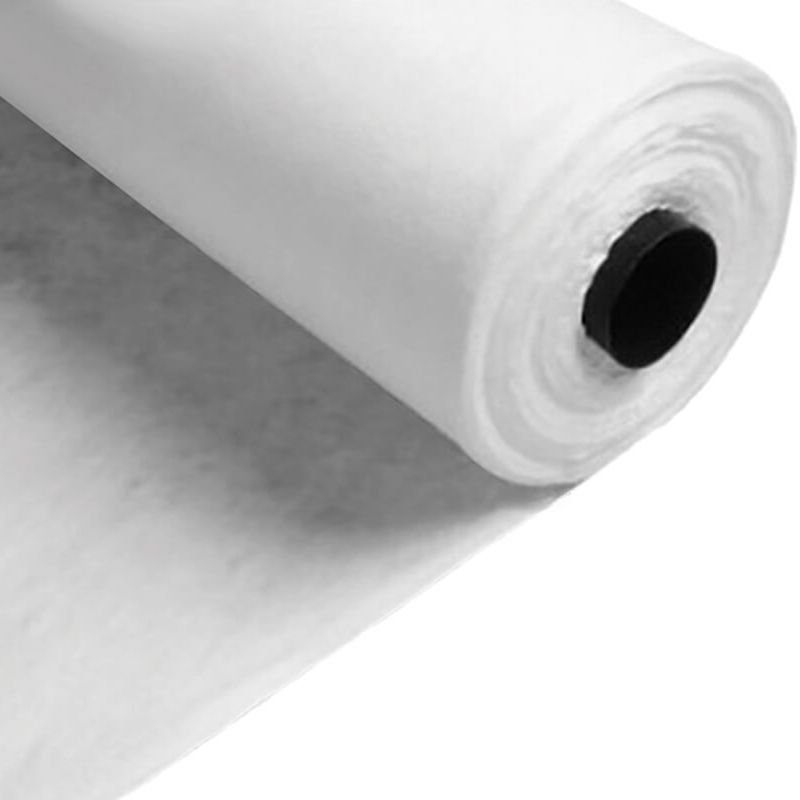
Woven Geotextile Membrane
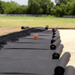
When selecting woven geotextile, always rely on the factory test data, not how the material feels by hand. Polypropylene pellets are stretched at high temperature into flat tapes 2.5 to 3 mm wide, then woven into black rolls. Tactile inspection alone tells you nothing about load-bearing capacity.
Measured tensile data is the real criterion. Under ASTM D4632, a 4 × 8 inch specimen is clamped and pulled until failure. The load at break determines whether the soil underneath will remain stable under traffic.
The percentage by which a specimen elongates before it breaks is called elongation.
For woven fabric, elongation must remain below 15%. A non-woven can stretch to 50%, which means that under 6 inches of stone it may still settle 3 inches into the subgrade. Woven fabric stays taut like a drum skin and holds soft soil firmly in place.
- Backyard pedestrian path: minimum tensile strength 150 lbs
- Private driveway for passenger vehicles: minimum 250 lbs
- Heavy trucks and construction vehicles: at least 315 lbs
Angular stone under pickup tires can generate pressures close to 80 psi. Under ASTM D6241, a 50 mm flat-ended steel plunger is pushed down onto the center of the material. The woven fabric should withstand at least 700 lbs of force without puncturing, otherwise subgrade mud will pump up through the hole.
The fabric also needs to pass water while retaining fine subgrade soil. Under ASTM D4751, the opening size is compared to standard sieve sizes. The material should match a No. 40 US sieve (0.425 mm) so that fine silt is retained while water passes through.
A No. 40 sieve is fine enough to retain beach sand-sized particles while still letting rainwater drain through.
Water flow rate must also stay within a practical range. Under ASTM D4491, permeability should generally fall between 4 and 10 gallons per minute per square foot. If it is only 1 gpm, stormwater cannot drain through the stone layer. If it exceeds 50 gpm, the openings are too large and subgrade slurry will wash upward.
- No. 30 sieve (0.60 mm): too open; red clay rises to the surface
- No. 40 sieve (0.425 mm): ideal balance; retains subgrade fines
- No. 70 sieve (0.212 mm): too tight; clogs with silt in about 3 days
Standard mill rolls are 12.5 feet wide and 300 feet long, covering about 416 square yards when fully unrolled. Adjacent sheets must never simply butt together.
On firm, dry red soil, overlaps of 12 to 18 inches are sufficient. In swampy mud where a foot sinks in and cannot be pulled back out, the overlap should be increased to 36 inches. If the overlap is too narrow, wheel pressure can pull the two sheets apart and let mud squeeze upward.
Overlap zones should be fixed with 6 inch U-shaped steel staples, installed every 5 feet.
Geotextile is often exposed to sunlight during installation, and UV attacks polypropylene directly. Under ASTM D4355, the material is exposed to xenon arc light for 500 hours, then retested. At least 70% of the original strength must remain.
Cheap agricultural weed barrier without UV stabilizers can become brittle after only 14 days in sunlight. Before aggregate is even placed, its strength may already have dropped to 30% of the original value. A light hit from a shovel can punch a hole straight through it.
The actual weight should also be checked. For driveway use, materials should generally fall within 4.0 to 6.0 oz/yd². 2.0 oz fabric is suitable only for weed control in garden beds.
- 2.0 oz: light weed barrier; an adult can step through it
- 4.0 oz: minimum practical weight for residential driveways
- 6.0 oz: suitable under 10 ton heavy construction trucks
During installation, the sheet must be laid flat and smooth, with no hard wrinkles or rolled edges. A wrinkle standing 2 inches high can reduce tensile strength in that area by 40% under load. Unopened rolls must remain wrapped in black plastic and protected from light. The covering should be cut open only when the gravel truck has arrived and installation is about to begin.
Correct Installation Techniques
Subgrade Leveling
Bring in an excavator and strip away the upper 300 mm of turf-bearing soft soil. If root-filled topsoil is left beneath the system, it will rot and leave voids within six months. After the dozer has leveled the ground, workers follow behind and remove every hard stone larger than 15 mm, all glass fragments, and all scrap steel by hand.
Before work begins, test soil moisture by hand. If a squeezed lump holds together but breaks apart naturally when thrown to the ground, the moisture content is around 12% to 15%, which is ideal. If the soil is too dry, water should be applied at 2.5 liters/m². If it feels spongy underfoot, it should be air-dried for 3 days, then treated with quicklime at 50 kg/m³ to absorb excess moisture.
Bring in an 18 ton single-drum vibratory roller and compact the ground with 6 to 8 passes.
Roller speed should be controlled at 3 to 4 km/h. If it moves too fast, trapped air cannot escape from the soil. The target is a compaction degree of at least 95%. Using a nuclear density gauge, inspectors should test 3 random points for every 1,000 m² of earthwork. Areas that do not pass must be rolled 3 more times.
Once compaction is complete, surveyors should use a total station to check the finished grade. Lay out a 3 × 3 meter grid and place a 3 meter aluminum straightedge on the ground. Gaps under the straightedge must not exceed 20 mm. High spots should be shaved down, while depressions should be filled with fine aggregate and recompacted.
Heavy construction traffic often leaves wheel ruts deeper than 50 mm. These must be excavated to a depth of 400 mm, removing all soft slurry inside. The area should then be backfilled with a 6:4 blend of crushed stone and stone dust. A 75 kg tamping rammer should compact the repair area for about 20 minutes, until no further settlement occurs.
A layer of fine sand acts as a cushion between angular soil lumps and the geotextile, preventing puncture.
Once the subgrade is leveled, place a bedding layer of washed medium-coarse sand. It must not contain stone larger than 5 mm, and the mud content must remain below 3%. A dozer spreads it evenly to a thickness between 50 and 100 mm.
Freshly placed sand is very loose and will show a footprint about 30 mm deep under a single step. Use a 1.5 ton light double-drum roller without vibration and make 2 static passes. After compaction, the sand should feel firm, hold a small amount of water briefly on the surface, and present a smooth, even support plane.
On sloped areas, shape the incline to a fixed 1:3 gradient. Sand alone will not remain stable on a slope, so it should be blended with 8% Portland cement. After wetting, the mix should be allowed to set slightly for about 3 hours. At the toe of the slope, excavate a drainage trench 300 mm wide and 300 mm deep.
When temperatures drop below 0°C, water in the soil freezes and expands by 9%. Frozen ground may appear firm but can collapse into 100 mm deep potholes after thawing. If frost is forecast, cover the freshly compacted ground with a 20 mm thick straw mat to preserve ground heat.
Special attention must be given to spots machines cannot reach:
- Along walls: compact the 500 mm strip next to the wall with an upright rammer for 4 passes
- Around pipes: excavate a 200 mm wide ring and fill it with bentonite
- Small puddles: pump out standing water 5 mm deep and use sponges to remove soft slurry
- Old-new interfaces: cut a 20 mm deep V-groove where new soil meets old concrete
Half an hour before laying the membrane, the site foreman should walk the area in flat rubber shoes and check it underfoot. No hard object should be felt, and no soft spot deeper than 10 mm should appear. A blower delivering 15 m/s air speed should then be used to remove the last leaves, grass, and debris.
Once final preparation is complete, there is only an 8 hour window before wind begins depositing new dust and sand, so the rolls must be brought in immediately.
A finished roll may be 50 meters long and weigh over 200 kg. Six workers should line up in two rows, standing about 8 meters apart, and grip the lifting loops along the edge. Working in step, they lift the material 150 mm off the ground and move forward at about 10 meters per minute, ensuring the sheet never drags across the sand.
Installation Tension
How tightly the sheet is pulled has a major effect on its long-term performance. If the fabric is stretched drum-tight, then covered with 300 mm of crushed stone, the sharp stone corners press straight down without any room for the material to deform. A vertical impact above 500 N can puncture the woven structure instantly.
On flat ground, the fabric should be laid with shallow undulations, like ripples on water. For every 100 meters laid, allow an extra 1.5 to 2 meters of material. Workers should lift and shake the edges to create waves 30 to 50 mm high. Once the gravel is placed, these waves flatten and absorb the load.
Temperature changes matter. Under strong midday sun, when the ground exceeds 40°C, polymer fibers soften and expand. By 5:00 p.m., if the temperature falls back to 15°C, the sheet contracts. If it was installed too tight in the morning, a cold night can split a seam open over 2 meters.
That is why installation should be scheduled carefully. The best periods are 6:00 to 8:00 a.m. and 4:00 to 6:00 p.m., when temperatures remain around 20°C and expansion is limited. If the material must be laid at noon, every 10 meters may lengthen by 150 mm. If 8 mm steel pins are driven in while the sheet is hot and expanded, nighttime cooling may pull them out.
Experienced crews adjust slack based on weather conditions:
| Weather Condition | Temperature | Extra Length per 100 m | Wave Height |
|---|---|---|---|
| Overcast, calm | 15°C–20°C | 1.5 m | 30 mm |
| Strong direct sun | Above 35°C | 2.5 m | 50 mm |
| Early morning cold | Below 5°C | 1.0 m | 20 mm |
| Gusty weather | Strong wind, Force 6 | Stop work | Use 10 kg sandbags |
Where the ground has hollows and depressions, the sheet must never be stretched over them in midair. It must be pressed down to follow the surface exactly. If it is left suspended and then covered with gravel, the unsupported section may be subjected to hundreds of kilograms of tearing force.
Tension control at the edges is also important. A 400 mm wide U-shaped trench should be excavated around the perimeter and all excess material placed inside. Do not backfill it immediately. Leave the sheet undisturbed for 24 hours so it can relax naturally with the temperature.
Special care is needed at these high-risk points:
- Pipe penetrations: cut an extra 100 mm of clearance around the pipe and tie it with a slip knot, not a rigid one
- Slope breaks: form a 150 mm deep buffer zone where the slope meets the platform
- Equipment start points: add an extra 2 meter long protective sheet beneath the roller start area
Mark out a 50 meter reference line on the ground and draw marks at both ends of the installed sheet. When lightly tensioned, the installed length should exceed the reference line by 800 mm, which indicates correct slack. If a tension gauge on the edge reaches 150 N, stop pulling immediately, because further force may deform the woven structure.
Too much wrinkling also creates problems. If a fold is taller than 80 mm, gravel may slide along it. Large stones can become trapped in such folds, and when tracked equipment passes over them, the stone and fabric act like scissors, cutting a large slit in a 2 mm membrane.
Workers should use wooden rakes to smooth the sheet. The rake teeth should be spaced 100 mm apart and drawn gently in the direction of gravel placement. Any wrinkle higher than 80 mm should be pulled flat, while small uniform waves should be preserved.
The quality inspector can check slack with a 10 meter nylon cord fixed between two ground pins. The taut cord is held 50 mm above the sheet. Measured with a ruler, any section more than 80 mm below the cord is too loose, while any area closer than 20 mm is too tight. Such areas should be marked with red paint and adjusted.
Pulling directly by hand is risky because the load is concentrated in the fingers. Once tension exceeds 200 N at the edge, permanent deformation can occur. Use wide-jaw pliers lined with 3 mm thick rubber padding. Fit one clamp every 2 meters, and have the crew pull in sync.
Work should never be done in rain. Once the woven sheet gets wet, its weight increases by about 40 g/m². Wet material is harder to handle, and workers naturally pull harder, increasing the risk of over-tensioning. When the sun returns and the fabric dries, it shrinks back into a dangerous straight line.
Overlapping and Sewing
When two sheets are joined, the seam must withstand the compressive load of the gravel above. On a firm, well-compacted base with level variation within 15 mm, an overlap of 300 to 350 mm is generally sufficient.
Where the subgrade is soft and the CBR falls below 2.5, the overlap should be increased to 500 to 600 mm to prevent movement from pulling the sheets apart. In muddy soft ground, a 1 mm layer of bentonite paste should also be applied between the overlapping sheets to improve sealing.
Wind and temperature can affect the overlap during installation, so site conditions should be considered carefully:
- If temperature drops below 5°C, increase overlap by 50 mm
- If wind exceeds 5.5 m/s, place a 10 kg sandbag every 5 meters
- On slopes steeper than 1:4, the upslope sheet must overlap the downslope sheet
- Parallel longitudinal seams must be staggered by at least 1.5 meters
A portable bag-closing sewing machine should be operated at 1,200 to 1,500 rpm. If the speed is too high, the needle heats up. Once it exceeds 120°C, it may melt the plastic sewing thread. Use industrial round-point needles in sizes No. 9 to No. 11, which create holes about 1.5 to 2.0 mm in diameter. Larger needles may cut the woven tapes themselves.
The presser foot force should be adjusted to 3.5 to 4.0 kg. If it is too light, the stitch line will wander; too heavy, and it will create a permanent crease about 0.5 mm deep.
Use UV-resistant polyester sewing thread. A single strand should have a breaking force between 120 and 150 N. Ordinary cotton thread absorbs about 8% moisture and can lose 60% of its strength within 3 months underground. Polyester absorbs only about 0.4%, and after 50 years underground can still retain 85% of its original strength.
Select heavy thread in the 2000D to 3000D range. A coarse thread body helps seal the needle holes so that even 0.075 mm silt cannot migrate through with groundwater.
A single line of stitching is not reliable enough under heavy stress. The standard field method is a double-thread double-chain stitch.
- Two parallel stitch lines spaced 12 to 15 mm apart
- The first stitch line begins 50 mm from the sheet edge
- Stitch density should be 15 to 20 stitches per 100 mm
- Tension ratio between upper and lower thread should be 1:1.2
Once stitching is complete, a sample must be cut and tested destructively. For every 150 meters of seam completed, cut out a test sample measuring 300 mm × 200 mm. Set the tensile machine to 50 mm/min. A qualified seam should retain 70% to 85% of the base material strength.
If the test load exceeds 800 N per 5 cm and the membrane itself fails before the seam thread breaks, the seam passes. If the thread breaks first, an additional parallel seam must be sewn alongside the full 150 meter section.
Where soil pH is below 4 or above 10, apply a liquid polyurethane sealant over the stitched area. The coated width should fully cover the seam zone, with a thickness of 1.5 to 2.0 mm. At 25°C, allow about 45 minutes for the surface to dry into a waterproof film.
Machine handling also affects seam quality. Because the sewing machine weighs 5.5 to 6.5 kg, it should be suspended from an elastic support cord to reduce operator fatigue.
A slight deviation in stitch alignment is acceptable, but not more than 50 mm over a 10 meter section. Bright fluorescent yellow thread is often used on black geotextile so the stitch line can be checked visually.
Inspectors should watch for these visible defects as work progresses:
- Skipped stitches: 2 consecutive stitches without thread engagement
- Failed lock: the lower thread has not formed a proper locked loop
- Raised folds: material bunched more than 20 mm high
- Loose ends: broken thread tails longer than 10 mm
Any puncture hole must be patched with a piece extending at least 150 mm beyond the damaged edge on all sides. The four corners should be rounded off with a radius of 50 mm.
The new stitch line should begin 25 mm outside the old needle holes. New stitching should overlap the previous seam by 100 mm to lock the thread ends in place. If multiple sewing machines are used on the same project, they must be kept at least 15 meters apart. If machines are too close together, vibration traveling through the sheet can distort newly sewn seams.