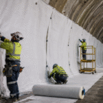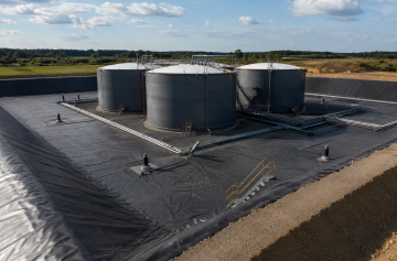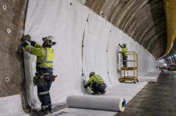
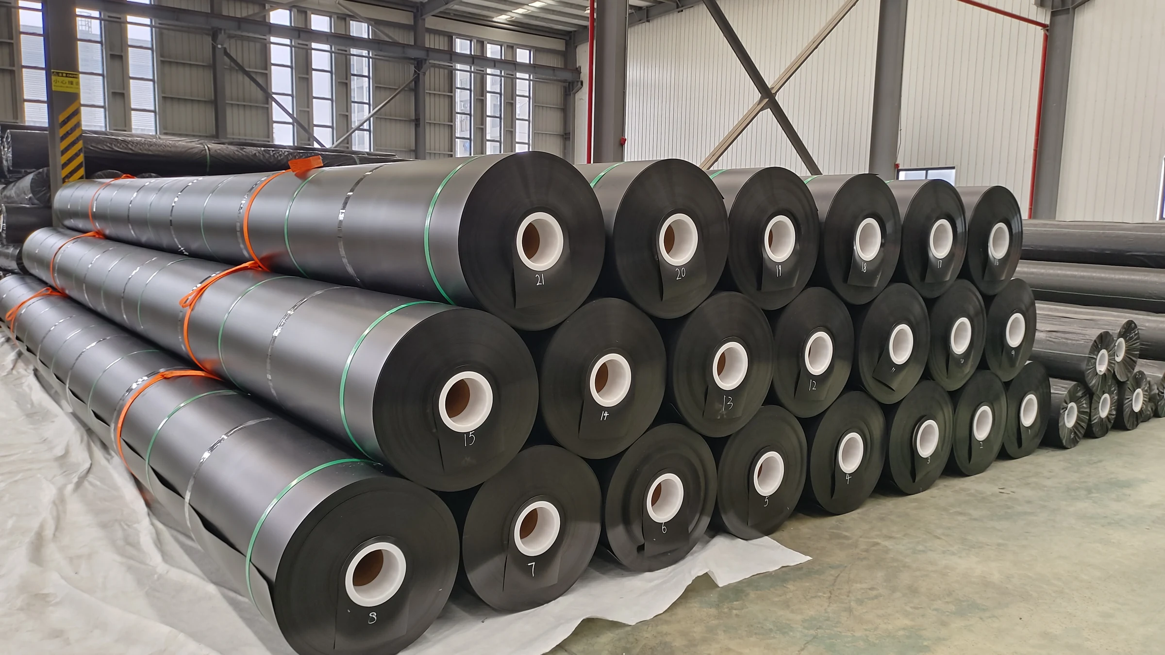

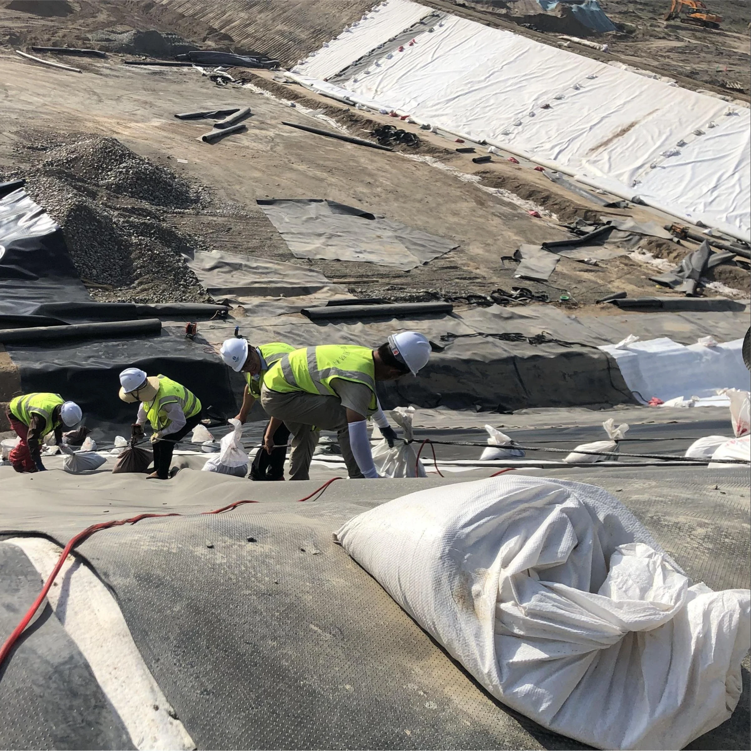

A useful geotextile protection trial should produce measurable results: the exact liner and geotextile tested, aggregate size and source, minimum cover, equipment and traffic, maximum rutting, remaining cover, and the number and type of liner defects found after excavation. A pass only makes sense for the construction conditions that were actually tested. GRI Guide GS11 treats protection test pads as site-specific and product-specific evaluations.[1]
| Trial Item | What Should Be Recorded |
|---|---|
| Geomembrane | Polymer, product, nominal thickness, smooth/textured surface |
| Protection geotextile | Product, GSM, nominal thickness, relevant mechanical properties |
| Aggregate | Source, gradation, maximum size, angularity, oversize |
| Cover | Planned thickness and minimum measured thickness |
| Equipment | Model, operating condition, tracks/tires, width |
| Traffic | Passes, reversing, turns, repeated traffic |
| Post-test condition | Ruts, remaining cover, geotextile damage, liner damage |
Lock the Test Conditions
Before aggregate goes down, agree on exactly what will be tested. If something changes during the trial, record it rather than treating it as though the original plan was followed.
- Use the same HDPE geomembrane planned for production.
- Use the actual protection geotextile product, not only the same nominal GSM.
- Use production-representative aggregate.
- Use the planned minimum cover rather than an easier, thicker layer.
- Use representative equipment and operating loads.
- Include repeated traffic or turning if those movements will occur during production.
- Set pass, review, and fail criteria before excavation.
For a confirmation trial, keep these variables close to the planned production method. If the purpose is to compare options, change one main variable at a time where practical. GRI GS11 allows protection materials and stone-layer conditions to be compared in separate test-pad configurations.[1]
Size the Test Pad
A pad that is too small can give a misleading result. The machine needs enough room to travel, reverse, and turn in the same way it will during actual construction.
GRI GS11 gives dimensional guidance based on the equipment used in the test:
- above-ground pad width: at least 100% greater than the agreed placement or compaction equipment width;
- below-ground pad width: at least 50% greater than the equipment width;
- constant-thickness pad length: 300% greater than the agreed equipment length, corresponding to a total of four equipment lengths;
- for variable-thickness pads, GS11 uses the wording “5 to 10 times greater.” Confirm the total pad length and test zones in the accepted trial plan rather than treating that wording as an unqualified 5–10-length rule.[1]
If the selected machine is 3.0 m wide, the width guidance corresponds to approximately 6.0 m for an above-ground pad and 4.5 m for a below-ground pad.
GRI GS11 also notes that side confinement becomes more difficult for an above-ground pad when stone thickness exceeds about 300 mm (12 in.). This 300 mm value is about how the test pad is built and restrained. It is not a universal liner-protection thickness.[1]
If straight travel, repeated traffic, and turning all need to be checked, mark those areas separately before the test starts.
Prepare the Subgrade and Liner
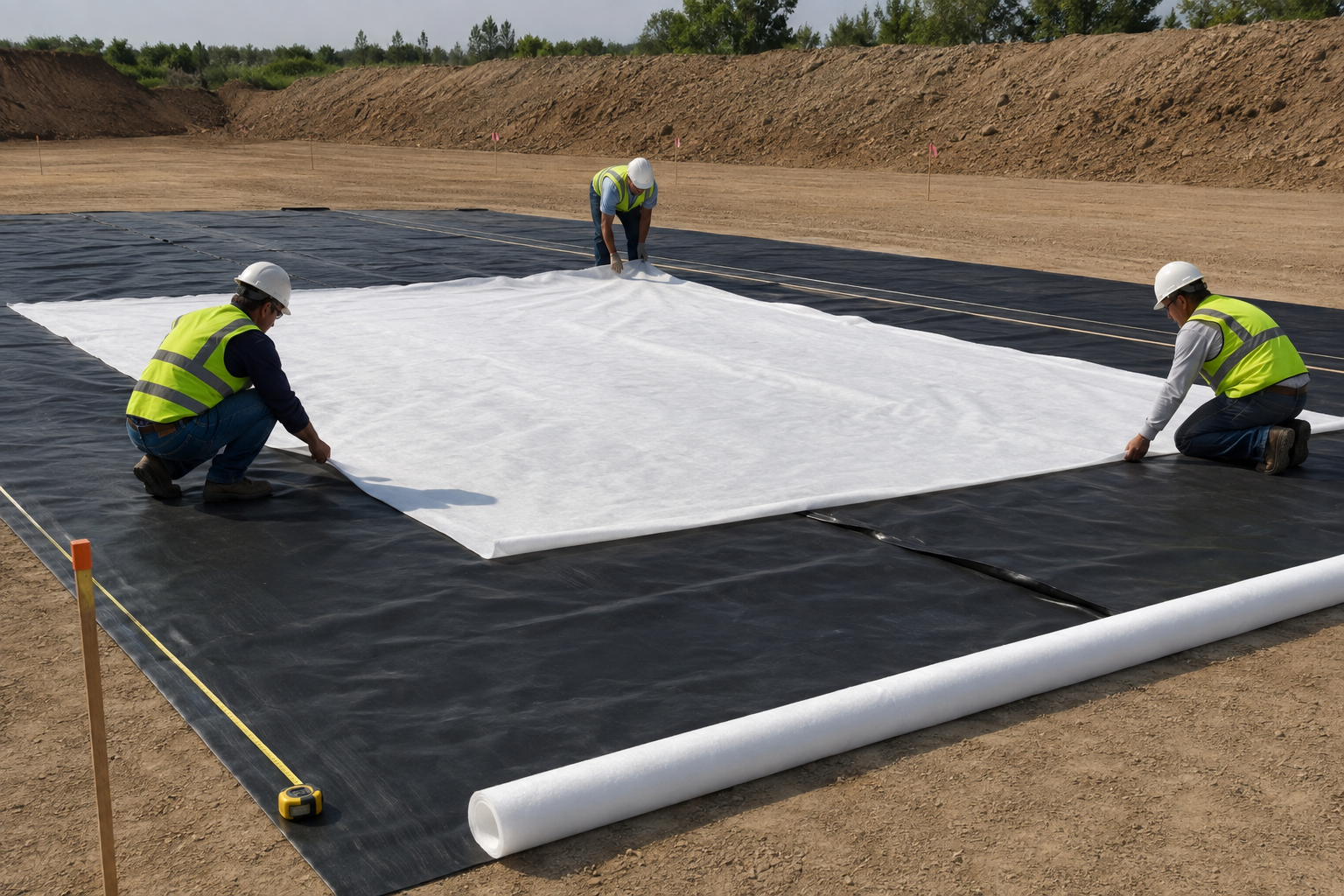
The trial should start on the same kind of prepared surface that would be accepted for production work.
| Check | Action Before Covering |
|---|---|
| Sharp stone | Remove it |
| Metal or concrete fragment | Remove it |
| Deep rut or footprint | Regrade where required |
| Soft or disturbed area | Review and repair before testing |
| Existing liner scratch | Photograph and mark it |
| Seam or repair | Record its location |
| Significant wrinkle | Measure or photograph its location before covering |
A stone below the geomembrane can become a puncture point when aggregate and equipment load are applied from above. Foundation condition is therefore part of the trial, not something to ignore once the liner has been installed.[1]
For scale, GRI GM13 covers HDPE geomembranes with nominal thicknesses from 0.75 mm (30 mil) to 3.0 mm (120 mil).[5] In other words, the barrier itself may only be a few millimeters thick while the stone placed above it is many times larger.
Manufacturing properties such as density, carbon black, OIT, thickness, and stress-crack resistance still need to be checked separately. They are covered in this GRI GM13 specification guide.
Set the Protection Geotextile
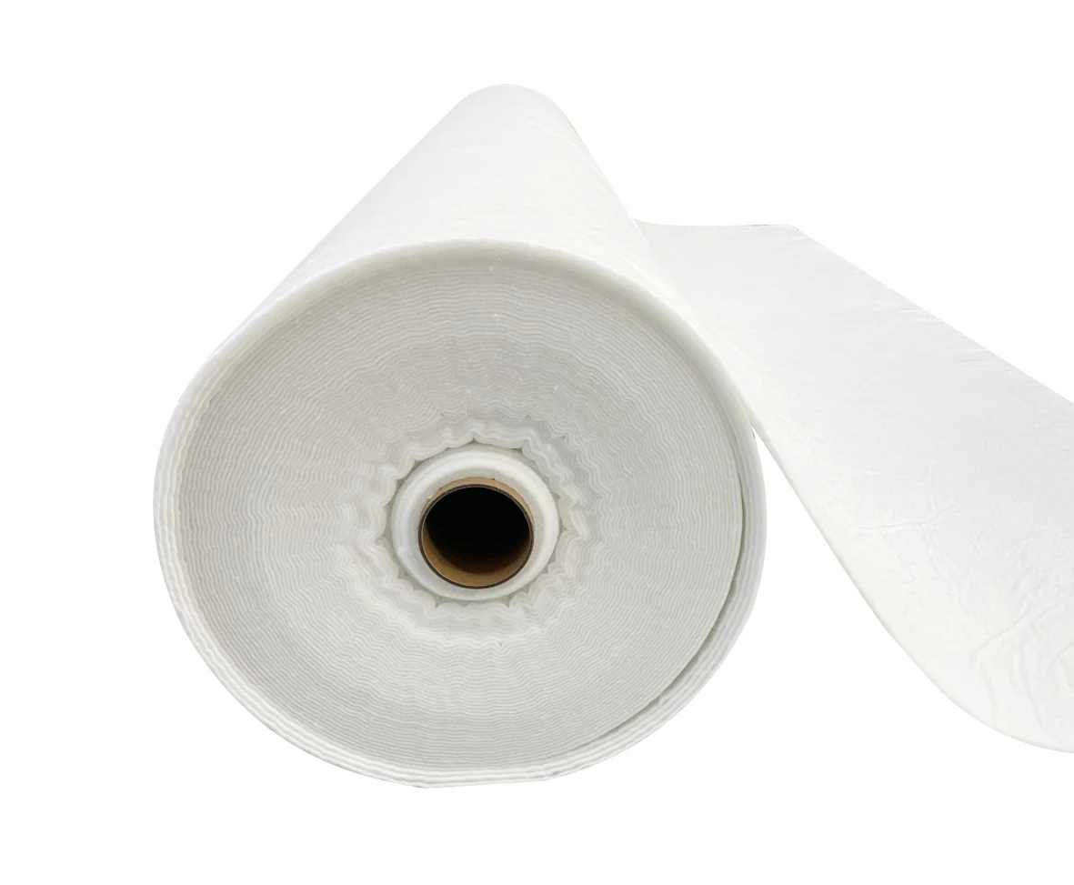
Use the actual nonwoven geotextile planned for the project and record the product identification before it is covered.
GRI GT12(a) lists protection-geotextile classes with mass per unit area values including:
| GRI GT12(a) Mass Class | Equivalent oz/yd² |
|---|---|
| 340 g/m² | 10 |
| 406 g/m² | 12 |
| 542 g/m² | 16 |
| 812 g/m² | 24 |
| 1080 g/m² | 32 |
| 2000 g/m² | 59 |
GRI GT12(a) also specifies properties such as grab tensile strength, tear strength, CBR puncture strength, and UV resistance.[2]
GSM is useful for identifying and comparing products, but it is not a field puncture rating. ASTM D5261 measures mass per unit area as an index property used for specification and quality control.[3] ASTM D5199-25 also notes that geosynthetic thickness can change considerably with applied normal load.[4]
Before aggregate placement, check the installed geotextile for:
- open gaps;
- folds or bunching;
- torn areas;
- stones trapped underneath;
- bridging over depressions;
- overlaps that can open when aggregate is pushed across them.
For overlap, debris, hard-point, and cushion-placement details, see the geotextile cushion installation procedure.
Use Representative Aggregate
The trial should use the aggregate the crew is actually expected to place, not a cleaner or more uniform batch selected just for testing.
| Aggregate Item | Record |
|---|---|
| Source | Quarry, supplier, or stockpile identification |
| Gradation | Approved grading or latest test result |
| Maximum particle | Largest expected/observed size |
| Oversize | Presence and approximate frequency |
| Shape | Rounded, subangular, angular |
| Foreign material | Metal, concrete, wood, debris |
EPA CQA guidance identifies particle size, hardness, and angularity as factors that can affect geomembrane damage during backfilling.[6]
A few oversized particles can matter even when most of the aggregate is smaller. One angular stone under a loaded track can create a much harder local contact than the rest of the layer.
As a simple scale example, a 75 mm rock is 50 times the nominal thickness of a 1.5 mm geomembrane. This ratio does not predict failure; it simply shows why stone shape, cushioning, cover, support, and equipment loading have to be considered together.
Control the First Lift
The first lift is where placement problems show up quickly. The crew should be watching the leading edge of the aggregate, not only the machine.
| Problem | What It Looks Like | Field Response |
|---|---|---|
| Impact | Stone drops directly onto thin or exposed protection | Reduce uncontrolled drop and correct the placement method |
| Rolling | Large stone rolls down a pile toward exposed geotextile | Stop and remove/reposition the particle |
| Pushing | Aggregate moves as a mass and drags the geotextile | Reduce pushing force and restore the protection layer |
| Thin cover | Placement front or rut drops below the planned minimum | Restore cover before further traffic |
| Equipment contact | Blade, track, bucket, or tire reaches exposed geosynthetic | Stop work and inspect the area |
A common approach is to advance aggregate from material already placed so the spreading equipment stays on protected cover. The exact sequence still needs to match the method being tested.
Measure the Actual Cover
The number that matters in the field is the thinnest cover that remains over the protection layer, not the nominal lift written in the plan.
For example, a project may plan a 300 mm first lift but measure:
- 310 mm in the middle of the placed layer;
- 285 mm near the placement front;
- 250 mm after repeated equipment traffic;
- 230 mm at the bottom of a rut.
These values are an illustrative measurement set, not recommended limits.
If an illustrative 300 mm surface develops a 75 mm rut, the rut depth is 25% of the original nominal lift thickness. That does not mean 225 mm of cover definitely remains. Some of the movement may be in the aggregate, some in the subgrade, or both. The remaining cover should be measured directly.
Survey elevations, laser levels, or fixed grade references can be used where suitable. A sharp metal probe should not be pushed through the aggregate until it reaches the geomembrane.
Run the Traffic Sequence
Instead of letting the operator drive around freely, write down the planned sequence and record each pass as it happens.
| Pass | Equipment | Condition | Movement | Example Observation |
|---|---|---|---|---|
| 1 | Tracked dozer | Operating | Straight forward | No visible rut |
| 2 | Tracked dozer | Operating | Reverse | 20 mm rut |
| 3 | Loaded loader | Loaded | Straight forward | Local aggregate movement |
| 4 | Tracked dozer | Operating | Controlled turn | 55 mm rut |
All values in this table are illustrative and are not acceptance limits.
ASTM D7007-24 identifies machinery damage during placement of earthen material as a major source of leaks in covered geomembranes.[7]
Record the equipment model and total operating weight, but do not stop there. Track or tire configuration, loading condition, turns, reversing, and repeated passes all change how the load reaches the liner.
If tight tracked-equipment turns will be used in production, test them in a separate area. Turning can push aggregate sideways, reduce local cover, and deepen ruts even when straight travel causes little visible movement.
Measure Rutting and Remaining Cover
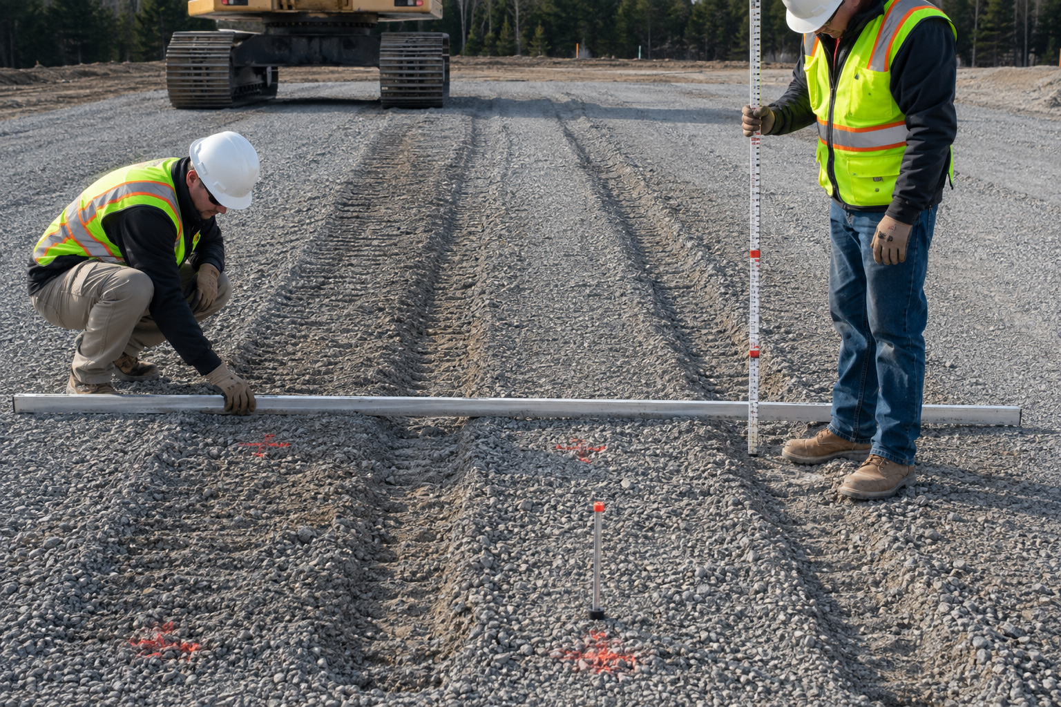
Once a rut appears, measure both the rut and the cover still left beneath it.
- maximum rut depth;
- location;
- equipment movement that created it;
- remaining cover above the geotextile;
- whether aggregate moved sideways;
- whether the supporting surface also deformed.
| Location | Rut Depth | Remaining Cover | Traffic |
|---|---|---|---|
| S1 | 20 mm | 280 mm | Straight pass |
| R2 | 35 mm | 260 mm | Repeated passes |
| T1 | 55 mm | 230 mm | Controlled turn |
This is an example record only. Project acceptance must use project-specific limits.
Excavate Without Adding Damage
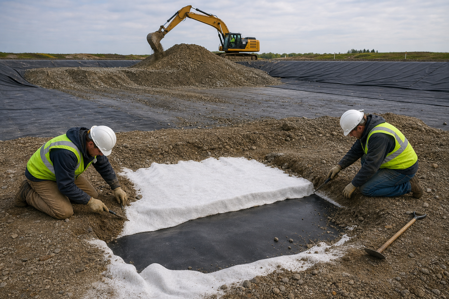
The test result is only useful if the liner is exposed without creating new damage during excavation.
GRI GS11 states that most stone may be removed mechanically, but when excavation reaches roughly 100 mm (4 in.) above the protection geotextile, removal should continue by hand to reduce the chance of damaging the geomembrane during exposure.[1]
When an unusual stone or damaged geotextile is exposed:
- stop local excavation;
- photograph the stone in place;
- record the grid location;
- measure the remaining cover where possible;
- record rutting and traffic at that location;
- remove the stone carefully;
- inspect the geotextile and geomembrane below it.
If a shovel, tool, or machine causes damage during excavation, mark that defect immediately as excavation damage.
Inspect and Map the Damage
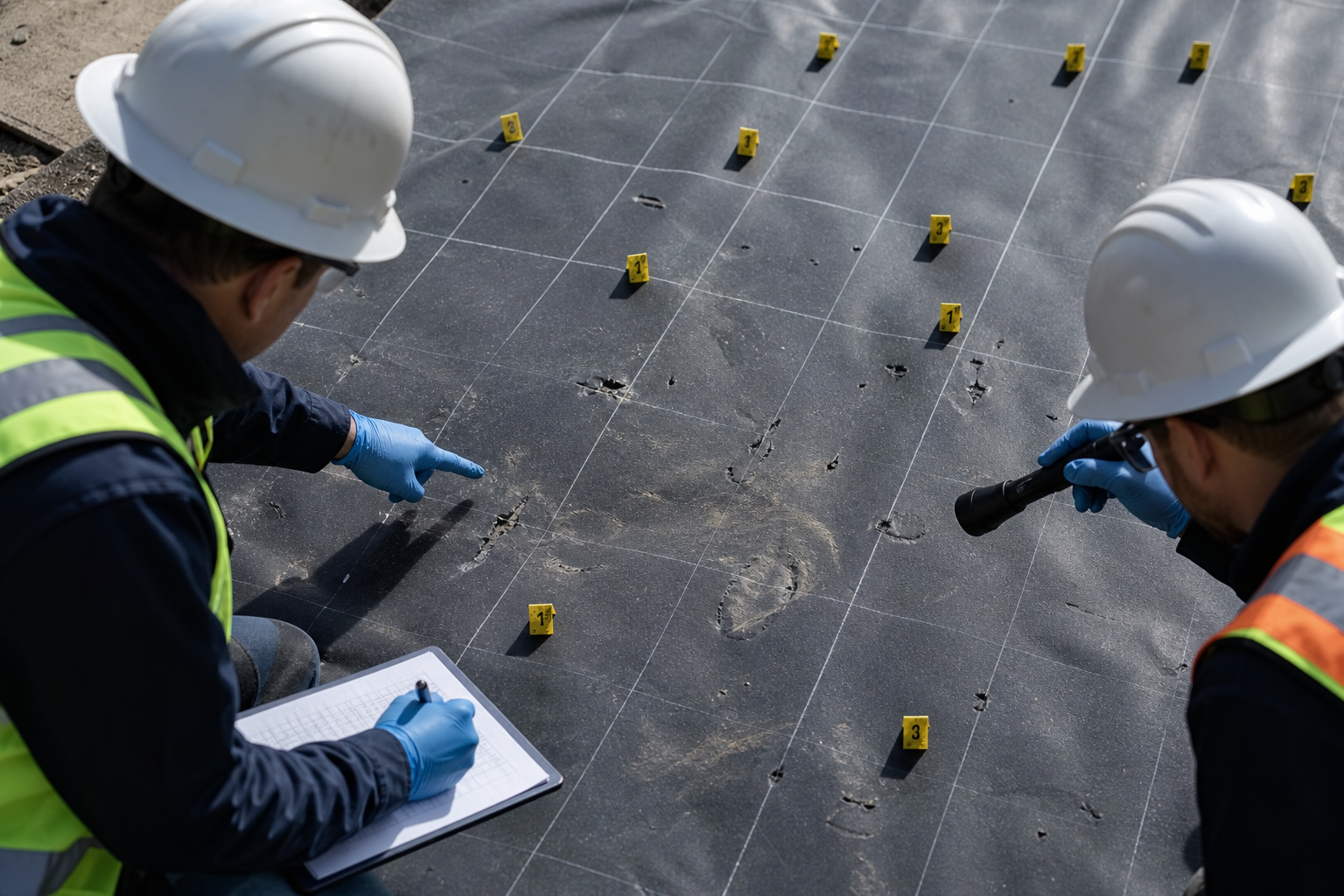
Inspect the geotextile first, then check the geomembrane directly below the same spot.
A practical inspection grid may use 1 m × 1 m cells such as A1, A2, A3, B1, B2, and B3. The grid size is only a recording choice.
| Finding | Field Description | Record |
|---|---|---|
| Surface scuff | Light friction mark with no obvious deep cut | Location and approximate size |
| Gouge | Deeper scratch or surface material removal | Length, width, direction |
| Indentation | Local depression without visible penetration | Diameter, depth, shape, stone above |
| Cut or tear | Linear break in the sheet | Length, direction, likely cause |
| Puncture | Through-thickness breach | Dimensions, stone, traffic, geotextile condition |
| Whitening | Lighter local area associated with deformation in some polymeric liners | Area, indentation, crease, nearby damage |
These descriptions are field-recording terms, not universal ASTM acceptance categories.
Example records:
- A3: indentation approximately 35 mm wide and 4 mm deep; angular stone located directly above; no visible through-hole; light whitening on one edge.
- B2: gouge approximately 60 mm long; geotextile abrasion at the same location; no visible through-thickness breach.
- T1: 55 mm surface rut; three sharp indentations concentrated inside the turning path; no similar indentations in the control area.
The dimensions above show how a field record can be written. They are not acceptance limits.
Seams and repairs also need their own check. Look at weld edges, seam intersections, patch corners, and places where a coarse particle sat beside a thickness change.
Where required, electrical leak location can supplement visual inspection. ASTM D7007-24 covers covered geomembranes, while ASTM D7953-20(2024) covers arc testing on exposed geomembranes.[7][8]
Use the Damage Pattern to Find the Cause
| Observed Pattern | Check First |
|---|---|
| One defect directly below a large stone | Oversize particle, particle shape, local cover |
| Damage concentrated in the turning zone | Sideways aggregate movement, rutting, reduced cover |
| Damage mainly at the placement front | Rolling stone, thin cover, geotextile displacement |
| Similar sharp dents throughout the test | General aggregate/protection/cover condition |
| Several defects following one straight line | Blade, tool, bucket edge, dragged object |
| Geotextile torn but liner intact | Extent of protection-layer damage and project criteria |
Judge the Result
| Result | Typical Field Finding |
|---|---|
| Pass | No unacceptable punctures, tears, seam damage, or deformation; required cover remained controllable; the method can be repeated in production. |
| Engineering Review | No visible through-hole, but sharp indentations, heavy geotextile damage, severe rutting, unusual seam deformation, or difficulty maintaining cover are present. |
| Fail | Confirmed puncture, unacceptable tear or seam damage, unacceptable deformation, uncontrolled geotextile movement, or inability to maintain the required construction condition. |
General values such as 300 mm cover, 55 mm rutting, or a 4 mm indentation should not be used as universal pass/fail limits. Acceptance values come from the project design and responsible engineer.
A field construction trial also does not replace long-term protection analysis where that work is required. ASTM D5514/D5514M-24 provides large-scale hydrostatic puncture procedures for evaluating geosynthetics under controlled loading over site-specific support material.[9]
Correct the Failed Condition
| Likely Cause | Trial Change to Check |
|---|---|
| Oversized stone | Tighten maximum-size or oversize control |
| Insufficient cover | Increase or better control the first lift |
| Repeated traffic | Change route, machine use, or traffic frequency |
| Tight turning | Increase turn radius, prohibit pivot turns, or increase local protection |
| Protection geotextile | Change product or protection system |
| Subgrade problem | Remove protrusions, regrade, or repair weak areas |
Where possible, change the most likely cause first. If the control and straight-pass zones are acceptable but the turning zone is damaged, testing a revised turning method gives clearer information than changing every material at the same time.
Retest When the Build Changes
Review or repeat the trial when a change could materially alter the load reaching the liner:
- different geomembrane product or thickness;
- different protection geotextile;
- larger or more angular aggregate;
- new aggregate source with a materially different gradation;
- reduced minimum cover;
- different equipment or loading condition;
- substantially more traffic;
- new turning procedure;
- different foundation condition;
- production rutting more severe than the test.
Normal minor variation does not automatically require a new trial. Retesting becomes relevant when the change is large enough that the original test no longer represents the way the work is being built.
Record the Trial
A useful trial report needs measured values, not just photographs and the word “pass.”
| Record Item | Illustrative Entry |
|---|---|
| Geomembrane | 1.5 mm HDPE |
| Protection geotextile | 1000 g/m² needle-punched nonwoven |
| Aggregate maximum size | 75 mm observed maximum |
| Nominal first lift | 300 mm |
| Minimum cover before traffic | 285 mm |
| Straight passes | 4 |
| Reverse passes | 2 |
| Controlled turns | 2 |
| Maximum rut | 55 mm |
| Minimum cover after traffic | 230 mm |
| Confirmed punctures | 0 |
| Mapped significant indentations | 3 |
The values above are an example of a completed field record. They are not project recommendations or acceptance limits.
Also retain:
- date, time, weather, and location;
- subgrade condition;
- product and roll identification;
- aggregate grading results;
- equipment model and loading;
- traffic map;
- rut locations;
- damage grid;
- photographs with scale;
- deviations from the planned procedure;
- final acceptance decision.
Standards Used
| Reference | Used For |
|---|---|
| GRI GS11[1] | Protection test-pad setup and field evaluation |
| GRI GT12(a)[2] | Nonwoven protection-geotextile property classes |
| ASTM D5261-10(2024)[3] | Geotextile mass per unit area |
| ASTM D5199-25[4] | Nominal geosynthetic thickness |
| GRI GM13[5] | HDPE geomembrane material properties and thickness classes |
| EPA CQA Guidance[6] | Backfilling, aggregate, liner slack, and construction quality control |
| ASTM D7007-24[7] | Electrical leak location for covered geomembranes |
| ASTM D7953-20(2024)[8] | Arc leak testing for exposed geomembranes |
| ASTM D5514/D5514M-24[9] | Large-scale hydrostatic puncture performance testing |
Finally
A trial is useful when the production team can take its numbers and use them in the field. Record the tested geomembrane and geotextile, maximum aggregate size, minimum cover, equipment sequence, rut depth, remaining cover, and liner findings. If a nominal 300 mm lift falls to 230 mm in a turning rut, the 230 mm field measurement matters more than the original nominal value. When excavation reaches about 100 mm above the geotextile, GS11 calls for careful hand removal. Zero punctures alone are not enough if cover cannot be maintained or the same sharp indentations keep appearing. Production should stay within the conditions that actually passed the trial.