
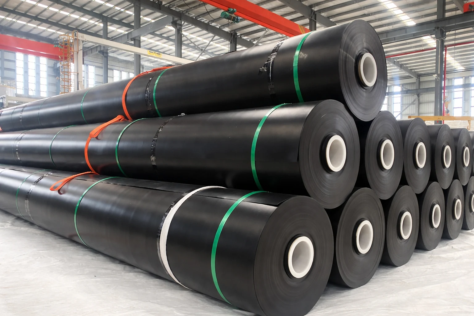
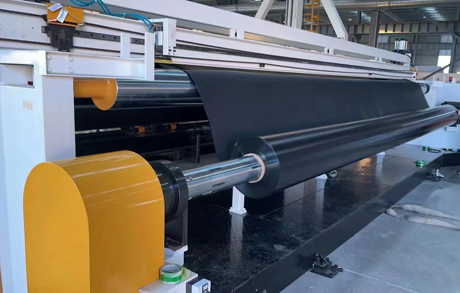
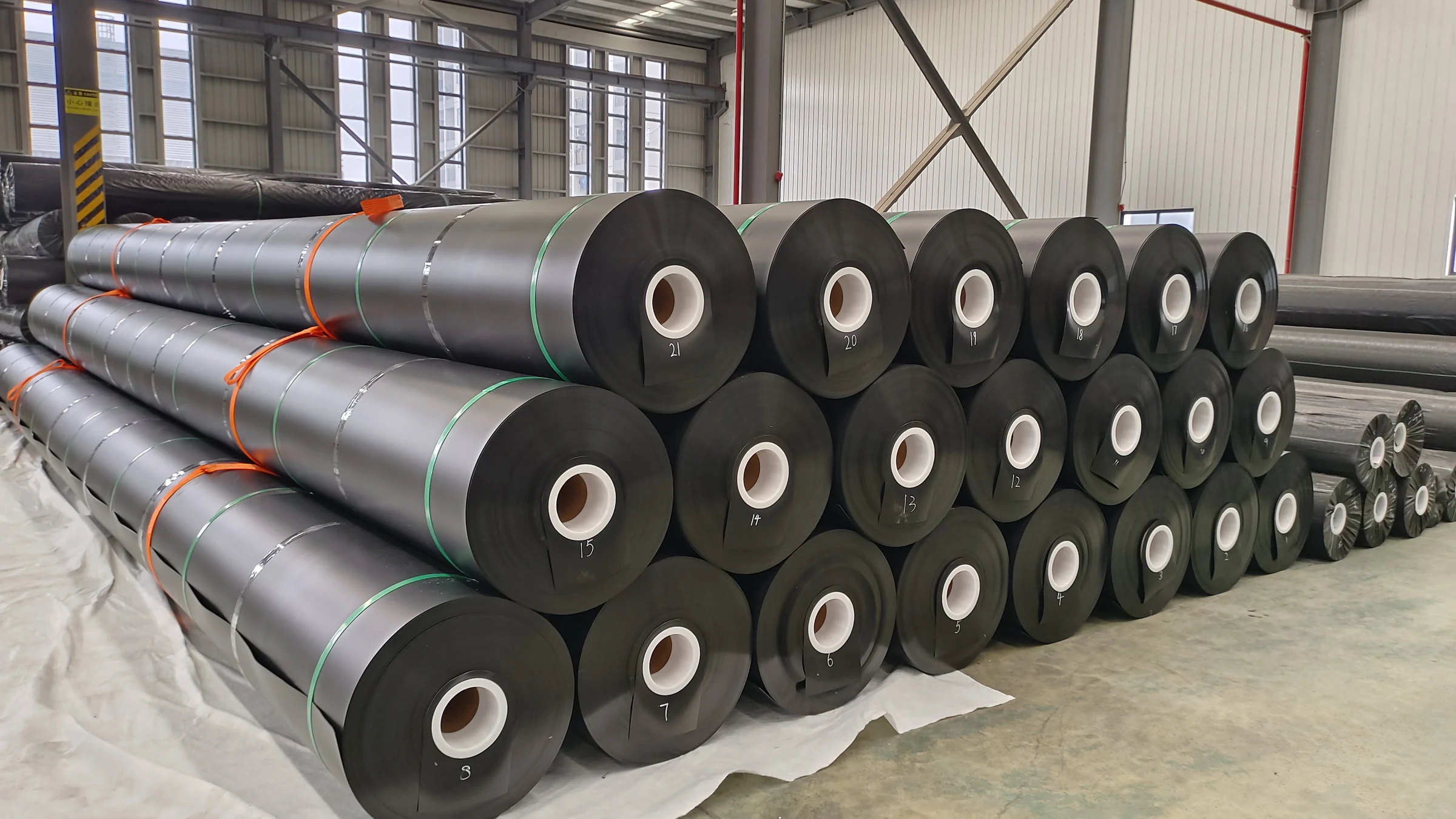
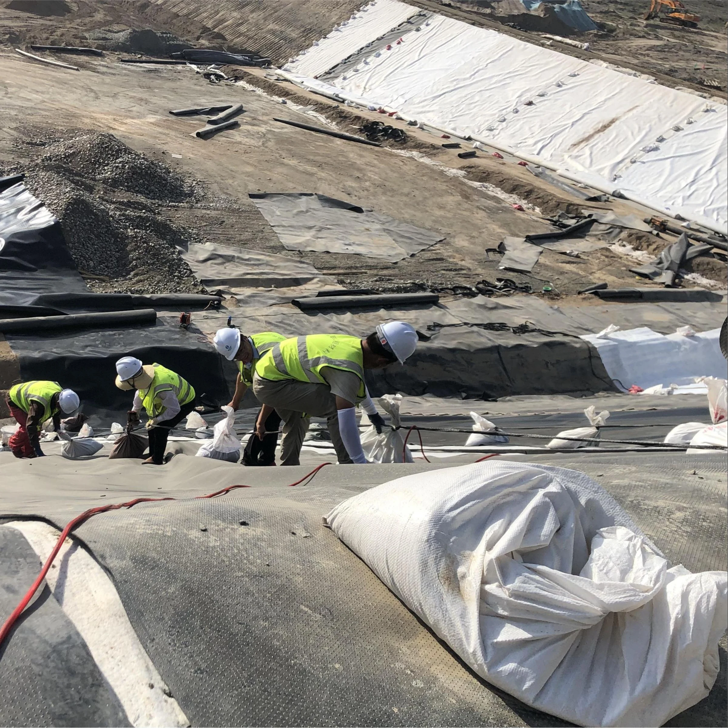
Smooth HDPE
Consider where the approved design permits a smooth surface. Review foundation contact, seams, thermal movement and all adjoining interfaces.
View HDPE product information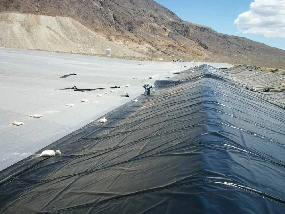
HDPE geomembrane provides a low-permeability barrier beneath or around the lined containment area. For a tailings facility, the material must be evaluated together with foundation preparation, drainage, protection, connections and anticipated deformation.
The Global Industry Standard on Tailings Management addresses facility responsibilities across the lifecycle. Purchasing a geomembrane does not demonstrate facility-wide compliance or establish dam stability.
Heap leach pads involve a different duty and loading environment. See the heap leach liner guide for that application. For other mining containment duties, see the mining applications overview .
Select each material for its function in the approved lining system. Surface texture, liner thickness and geotextile weight do not establish site performance on their own.
Consider where the approved design permits a smooth surface. Review foundation contact, seams, thermal movement and all adjoining interfaces.
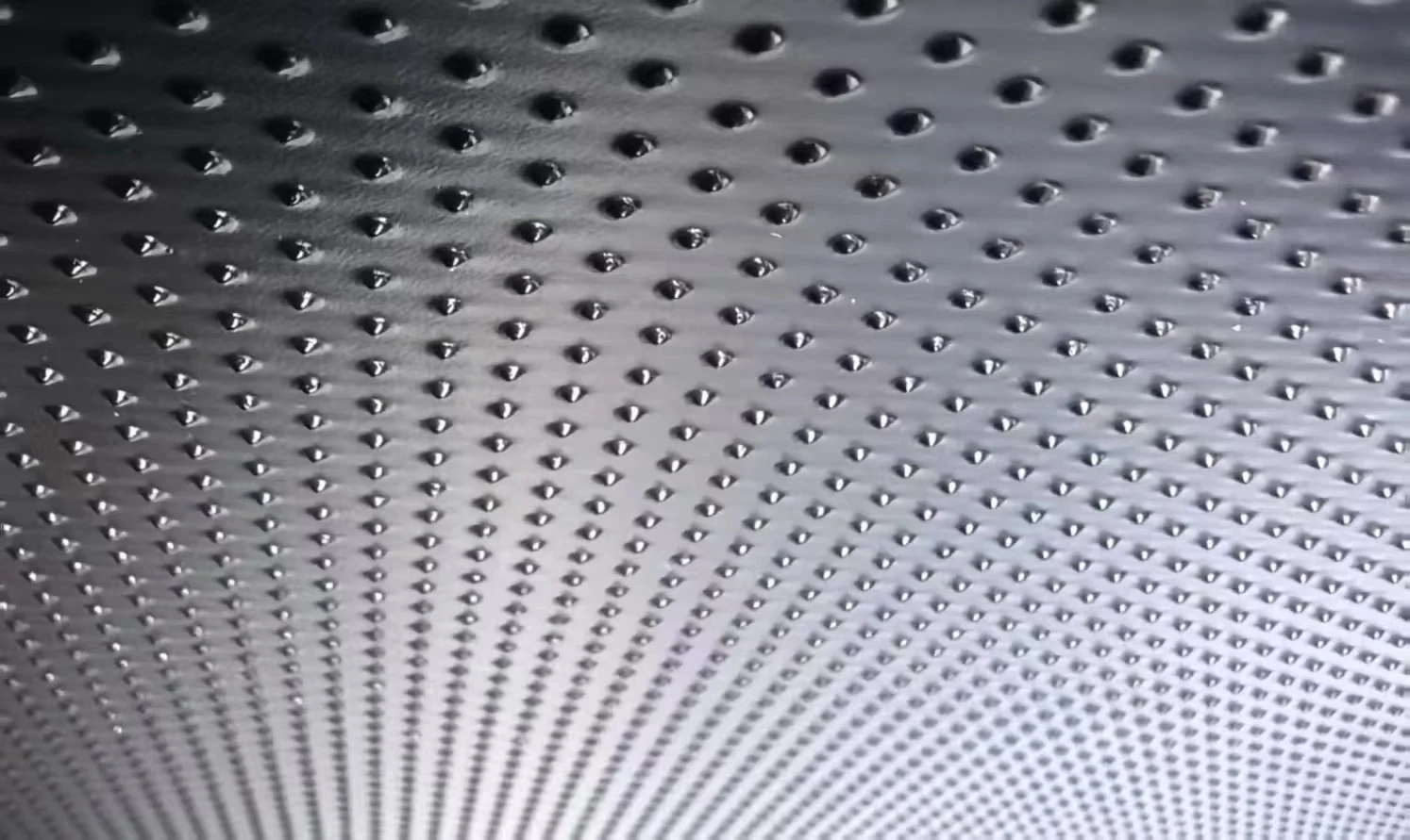
View HDPE product informationSpecify one- or two-sided texture when supported by the interface design. There is no universal friction angle or safe slope established by texture alone.
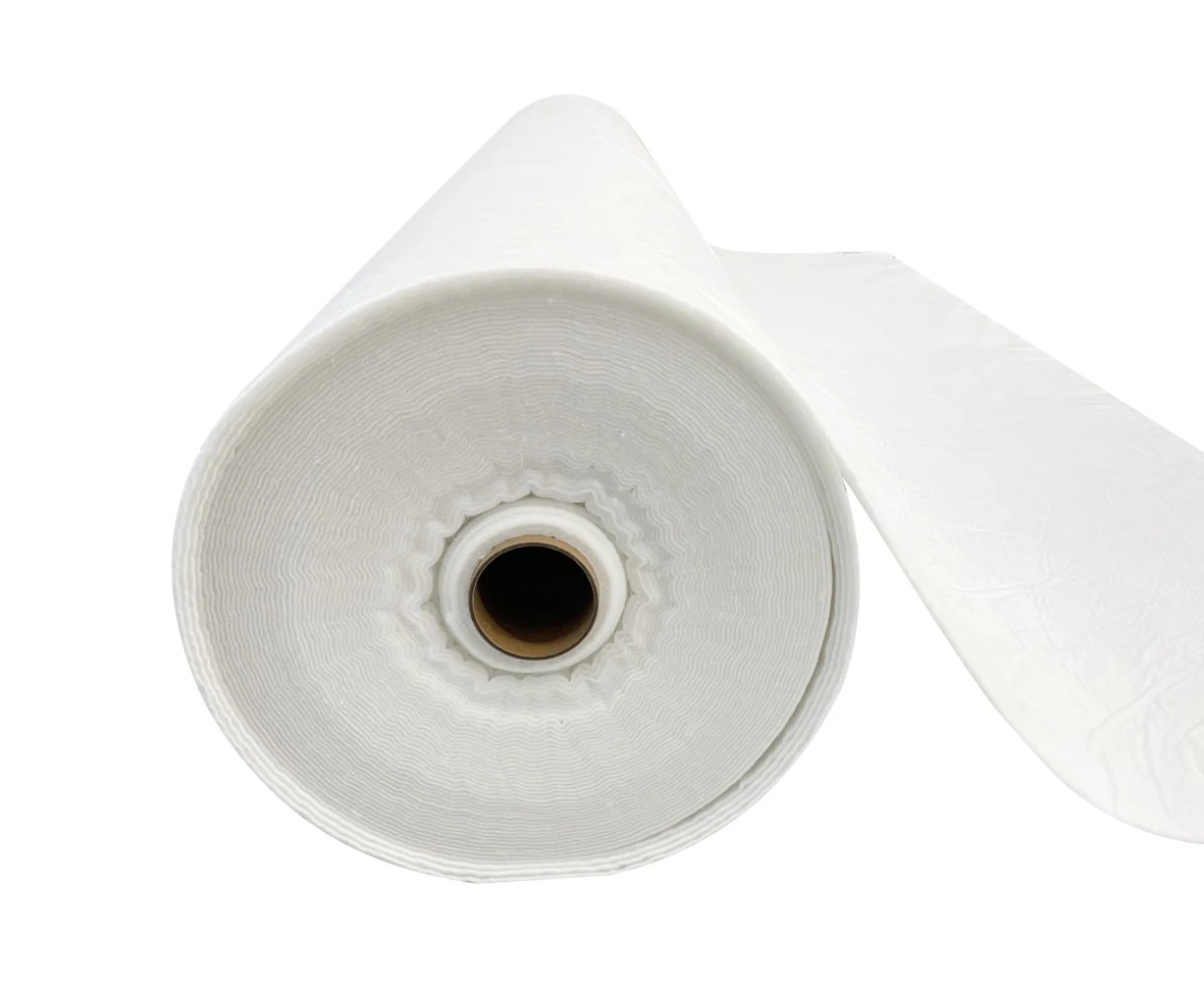
Review textured liner optionsSelect the cushion through the project puncture-protection assessment, considering contact material, loads, liner thickness and construction conditions. GSM alone is insufficient.
Review nonwoven geotextile| RFQ item | What to identify | What the review must resolve |
|---|---|---|
| Thickness and surface | Nominal thickness, tolerance, measurement method, smooth/textured faces and approved grade. | A 1.5 or 2.0 mm label alone does not establish resistance to site loading or settlement. |
| Liquid exposure | Actual pore-water or process-water composition, concentration, temperature range and potential oxidants. | pH alone cannot demonstrate compatibility. Review the formulation and representative exposure evidence. |
| Interfaces and slopes | Adjoining soil, geotextile or geocomposite; relevant stress, moisture and displacement conditions. | Use project-representative interface data and the designer’s stability assessment. |
| Foundation and protection | Subgrade roughness, particles, soft spots, differential settlement and construction equipment. | Approve preparation and the protective system before deployment; more thickness cannot correct a defective foundation. |
| Drainage and pressure | Underdrainage, uplift conditions, leak-detection provisions where required, and discharge arrangements. | A liner does not replace groundwater control or the approved water-management design. |
| Joints and penetrations | Anchor details, concrete connections, pipe boots and staged construction tie-ins. | Agree materials, access, weldability and acceptance criteria for each detail before supply. |
Interface reference: ASTM D5321/D5321M-26 covers direct-shear testing of soil–geosynthetic and geosynthetic–geosynthetic interfaces. Results apply to the materials and conditions tested; GCL interfaces are addressed separately.
HDPE or LLDPE? Where deformation is a controlling issue, the designer may evaluate an LLDPE alternative . Neither polymer type guarantees chemical resistance or an acceptable service life. Substitution requires review against the project specification and authorized approval.
GRI-GM13 addresses manufacturing test methods, properties and frequencies for smooth and textured HDPE geomembranes. State the contract-required edition and product table in the submission.
Material conformity does not replace chemical compatibility assessment, liner-system design or field construction acceptance. Request the full Jinseed HDPE data sheet , then identify the evidence applicable to the proposed product and actual production.
For chemically demanding tailings water: ASTM D5747/D5747M-21(2026) provides procedures for a chemical-resistance testing program, used with the relevant exposure practice. It does not itself establish a pass/fail compatibility rating. Qualified interpretation and project acceptance criteria remain necessary.
Check whether a test report covers delivered rolls . A qualification sample is not automatically proof for every later batch.
The take-off should follow the approved surfaces and panel layout. Add slopes, benches, anchors and details where applicable; identify overlaps, cutting allowances, spare material and packaging separately. Do not hide all allowances inside an unexplained percentage.
These dimensions and quantities are a hypothetical purchasing example, not a standard roll configuration or a net coverage guarantee. Actual usable area comes from the approved roll-to-panel layout.
Use actual thickness, formulation density and packing weights for logistics. Cores, wrapping, pallets, loading limits and surface profile are outside this simplified calculation.
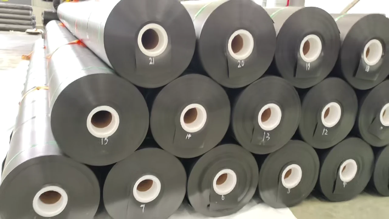
Confirm access, unloading equipment, protected storage, panel sequence and required documents for each shipment. Compare offers on the same area, product, testing scope, Incoterm and destination.
Plan phased geomembrane deliveriesA passing factory report cannot demonstrate that every field seam, penetration and installed panel is defect-free. Keep receiving checks, installation records and the construction quality assurance plan connected.
For system detail, read the tailings storage facility liner-system guide . That guide addresses system configuration; this page supports material selection and procurement.
Record subgrade preparation, groundwater conditions, protection-layer acceptance and any restrictions on deployment.
Maintain roll-to-panel mapping, weld logs, agreed nondestructive and destructive seam tests, repairs and detail inspections. Select leak-location surveys for the actual liner configuration and site conditions where required.
Retain as-built records and acceptance decisions. Agree drainage, seepage and operational monitoring responsibilities throughout the facility lifecycle.
Range context: published mining-containment selection guidance . This reference discusses mining containment and primary barriers; it is not a tailings-specific thickness mandate.
For preliminary comparison, mining containment liners are commonly considered in the 1.5–2.5 mm range (approximately 60–100 mil); 2.0 mm (approximately 80 mil) is one option for a primary barrier. This is a comparison range, not a universal tailings design requirement. Final thickness must follow the approved engineering design and account for subgrade roughness, tailings loads, protection geotextile performance and differential settlement. Use the specified units and acceptance tolerances rather than substituting rounded mil labels.
Textured HDPE can increase interface friction relative to smooth HDPE for a given material combination, but texture alone cannot guarantee slope stability. Select the surface using representative interface direct-shear testing under ASTM D5321/D5321M and a qualified slope-stability analysis. Test conditions must represent the adjoining materials, normal stresses, moisture and relevant displacement; asperity height alone is not a design friction angle.
No—GRI-GM13 specifies baseline manufacturing properties, including sheet density, carbon black dispersion and OIT; it does not establish chemical compatibility with site-specific mine water. Conformity must be supported by the applicable manufacturing records. For acid mine drainage (AMD), cyanide-bearing leachates or elevated-temperature exposure, assess the resin formulation and actual liquid chemistry. Use ASTM D5747/D5747M testing procedures with an appropriate immersion program, such as ASTM D5322 laboratory immersion, and project-defined evaluation criteria; D5747 alone is not an immersion procedure or a pass/fail compatibility certification.
No—not every tailings facility is required to have a double geomembrane liner. Selection of a single- or double-composite lining system, and any leak-detection provisions, depends on environmental regulations, consequence classification, seepage assessment, hydrogeological conditions and the approved design. The material supplier should quote the specified arrangement and identify departures for authorized review.
Send the application and project location; specifications and drawings; required thickness and surface finish; estimated lined and purchased areas; liquid chemistry and temperature; test-report and sampling requirements; phased delivery schedule; and destination port or site. Identify unresolved items for technical review so the quotation can state its assumptions and exclusions.
Share the approved requirements or your current enquiry package. Ask for an itemized material offer, proposed roll configuration, document scope and delivery assumptions so your team can evaluate the same scope across suppliers.
Specification & drawings
Thickness, surface & estimated area
Liquid exposure & temperature
Delivery stages & destination
Exact proposed grade & departures
Roll dimensions & gross quantity
Available reports & sampling scope
Freight basis & delivery assumptions
This page supports material enquiries and technical submissions. Facility design, regulatory approval and construction acceptance remain with the parties authorized for the project.
Source notes updated: 18 November 2026. Supply dimensions are taken from Jinseed’s published HDPE product information. Calculation examples are illustrative; they are not a quotation or results from a named project.