
Manage geomembrane wrinkles by identifying the cause, controlling deployment and cover placement, and using an engineered restraint plan. Thermal expansion, unsupported bridging, wind uplift and groundwater or gas pressure are different problems; adding sandbags is not a universal solution.
For an illustrative expansion coefficient of 0.12 mm/m/°C, a free 100 m length subject to a 30°C increase grows by 360 mm, while an 8 m width grows by 28.8 mm. Neither number is the expected wrinkle height or the required anchorage allowance. An installed liner is restrained by friction, seams, anchors and adjacent layers.
This guide concerns field-installed HDPE geomembrane. Numerical examples are calculations, not Jinseed project records, guaranteed material properties or a substitute for the project’s installation and construction quality assurance (CQA) plan.
Identify the Type of Wrinkle, Void or Bulge
| Observation | Possible cause | What to investigate |
|---|---|---|
| Waves increase during sunshine and reduce as the sheet cools | Thermal movement restrained by contact and anchorage | Sheet temperature, panel layout and timing of cover placement |
| Liner is stretched across a corner, depression or pipe detail | Bridging or insufficient fitted material | Subgrade geometry, detailing and whether the sheet is under tension |
| Loose edge flaps or a panel lifts during gusts | Wind entering beneath an inadequately restrained panel | Temporary restraint, exposed area and weather stop-work conditions |
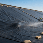
| A large dome persists or grows at low reservoir level | Possible underliner water or gas pressure | Groundwater, drainage and venting; do not assume it is thermal expansion |
| A sharp fold remains under cover or near a seam | A trapped wrinkle or installation damage | Repair assessment and the approved acceptance criteria before further loading |
Record panel and seam IDs, location, time, sheet temperature, water level and photographs before changing the installation. A photograph of a bulge alone cannot establish its cause.
Thermal Expansion and Contraction: Correct Calculation
For an unrestrained length, the basic estimate is ΔL = α × L × ΔT. Use consistent units: α in mm/m/°C, length L in metres and temperature change ΔT in °C give movement in millimetres. The relevant temperature is the sheet temperature, which can differ from air temperature.
| Assumed α | Length | Temperature rise | Calculated free movement |
|---|---|---|---|
| 0.12 mm/m/°C | 100 m | 30°C | 360 mm |
| 0.12 mm/m/°C | 8 m | 30°C | 28.8 mm |
| 0.12 mm/m/°C | 100 m | 60°C | 720 mm |
| 0.15 mm/m/°C | 100 m | 30°C | 450 mm |
| 0.20 mm/m/°C | 100 m | 30°C | 600 mm |
The 0.12–0.20 values are sensitivity assumptions. GSI White Paper 27, page 3, uses 0.15 mm/m/°C in an HDPE example. Obtain the proposed product’s coefficient and applicable temperature range before design. A calculation across the 100 m direction must not use the 8 m width by mistake.
Free expansion is not an instruction to add the same amount of loose membrane everywhere. Restraint changes displacement and stress. A universal allowance such as 1–2 mm per metre, a fixed 1.1 multiplier or 20–30% extra sheet length cannot replace the designed panel geometry, settlement allowance and anchor detail.
High Temperature and Wave Patterns
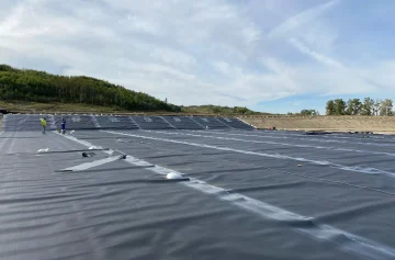
Schedule deployment, welding and covering together. Record the membrane’s condition at the temperature when the next operation will actually occur. Do not approve a flat-looking panel at dawn and assume it will remain flat when the earthworks crew covers it at midday.
GSI’s wrinkle research found that buried waves can become sharp folds rather than simply disappear under load. Its white paper discusses coordinated installation and cover-placement strategies, including cooler working periods, shading and purpose-manufactured lighter surfaces. These are options with practical constraints, not guaranteed temperature reductions or wrinkle-height limits. Read the research and its limitations.
The liner surface, wind conditions, welding procedure and available inspection access matter more than a universal clock-time rule. Morning or night work may help on a particular site, but the crew still needs suitable lighting, dry seams and a safe access plan.
Cooling Methods
Do not apply an unapproved cooling chemical, coating or solvent to the liner. Compatibility with the sheet and welding process must be confirmed before use. An unsupported claim that a spray increases cooling by a fixed percentage is not a basis for selecting it.
If temporary shade or a water-based cooling procedure is proposed, obtain installer and CQA acceptance first. Consider wind resistance of the shade structure, drainage, slip hazards and seam cleanliness. No universal water application rate, droplet size or 5–15°C temperature reduction is specified here.
Resting an unrolled panel can allow its condition to stabilize, but a fixed two- or four-hour wait does not prove temperature equilibrium. Measure and observe the actual sheet before fitting and welding.
Prevent Bridging and Unsupported Voids
The US Bureau of Reclamation’s Design Standards No. 13, Chapter 20, section 20.5.7.4, addresses relaxed deployment, thermal movement and avoiding bridging at changes in geometry. It also emphasizes coordinated placement and adequate temporary restraint. These principles do not prescribe one anchor-trench size for every site.
- Resolve protrusions, soft zones and abrupt changes in the accepted subgrade before covering them.
- Fit sufficient material at corners, slope toes and penetrations without leaving the sheet stretched across a void.
- Keep equipment off unprotected sheet and use the project’s approved access and cover-placement procedure.
- Stop the next operation when it would trap an unacceptable fold or conceal unresolved damage.
A 20 mm gap under a 2 m straightedge, CBR of 3%, or sand moisture of 8–12% is not a universal geomembrane foundation acceptance requirement. Record the actual project criteria and the test method. Soil type, compaction reference, settlement and drainage must be evaluated together.
Edge Looseness and Repair
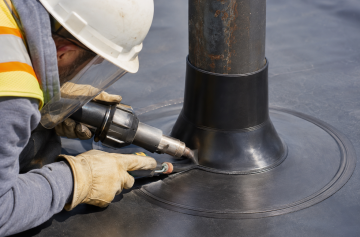
First distinguish a sound loose edge from a torn or stretched panel. Do not cut otherwise sound sheet merely because it has a temporary thermal wave. The installer and CQA representative should agree whether adjustment, replacement or a documented repair is required.
Use the approved overlap, surface preparation, welding method and cooling criteria. A claim that every hot-wedge repair needs 150 mm, every extrusion repair needs 200 mm, or every weld must cool for exactly 30 minutes ignores equipment and material differences. Higher welding temperature is not automatically a stronger repair.
For suitable dual-track seams, ASTM D5820 describes air-channel evaluation. ASTM D5641/D5641M addresses vacuum-chamber evaluation, with limitations at uneven surfaces, corners and other difficult geometry. ASTM D6392 covers destructive peel and shear testing of appropriate nonreinforced thermally fused seams. Use the applicable procedure and record repair locations and results.
Slope Movement and Anchorage
Do not treat the liner as a structural sheet that can safely hang from its crest under every load. Surface texture, adjacent materials, pore pressure, cover loading, slope geometry and anchorage interact. ASTM D5321/D5321M provides interface shear testing under specified conditions; a catalogue friction angle does not establish a safe slope.
GRI-GM13 is a manufacturing specification for HDPE sheet. It is not the source of a universal 300 × 200 mm anchor trench or a rule that slopes below 20° need no crest anchorage. Likewise, an index-test yield elongation is not an allowable long-term strain for an installed liner.
Include temporary and permanent conditions in the design. The restraint present during deployment may differ from the final cover system. If movement is being monitored, set survey accuracy, reference points and action thresholds in the monitoring plan; a generic 20 mm trigger does not fit every installation.
Ballast Systems: Weight Is Not a Wind Rating
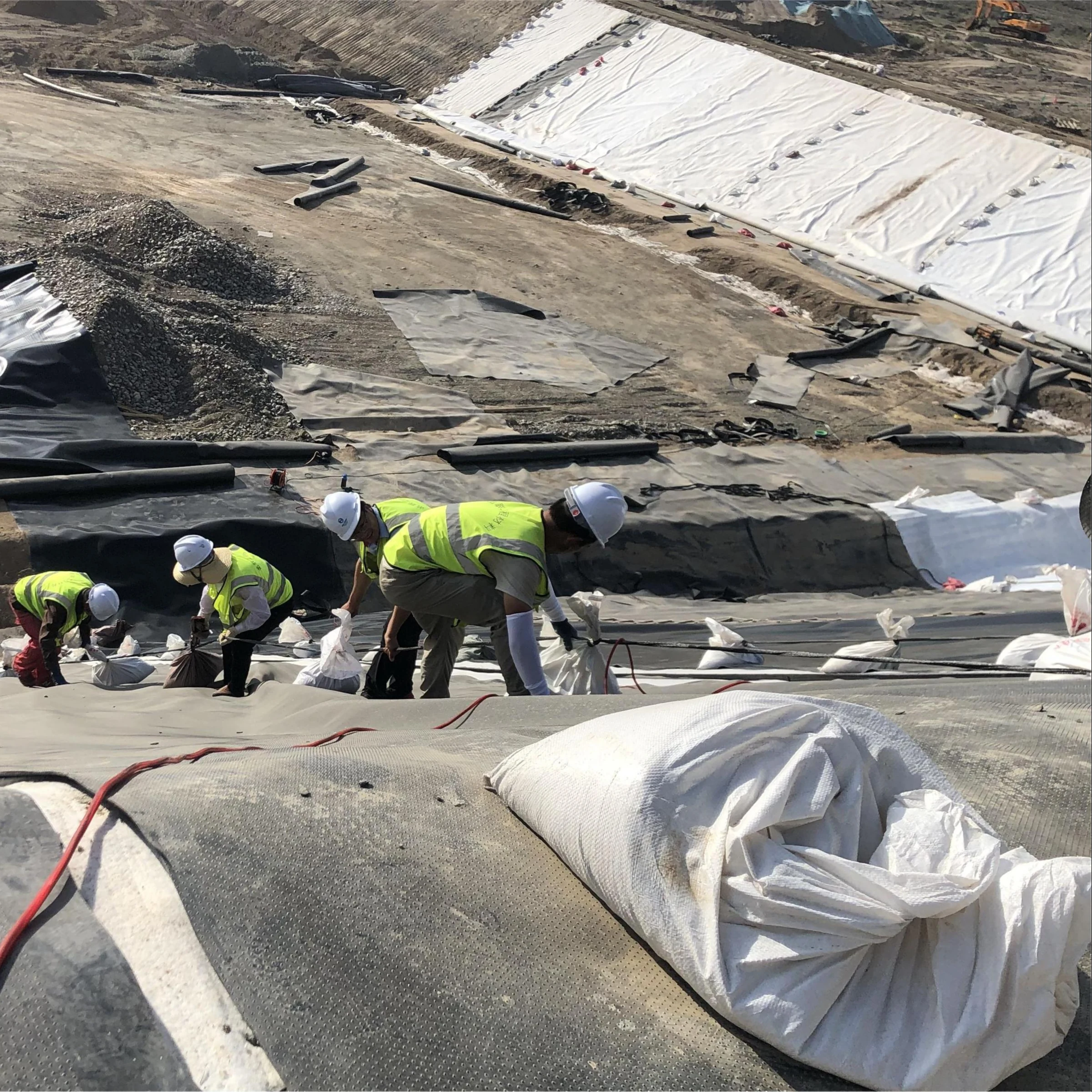
Temporary ballast must be compatible with the liner, securely positioned and checked against the expected exposure. Do not assume a fixed 1.5 m, 2 m or 3 m grid will resist a given wind speed. Edge uplift, aerodynamic effects, continuity of restraint, sliding and local damage need assessment.
For a simple horizontal weight calculation, an assumed 20 kg bag exerts about 196 N. Distributed over a 2 × 2 m tributary area, that is only 49 N/m², or 0.049 kPa. At 1.5 × 1.5 m spacing it is about 87 N/m²; at 3 × 3 m spacing, about 22 N/m². These are average gravitational loads, not allowable wind pressures or recommended spacings. On a slope, the bag can also slide and its normal force is reduced.
| Option | Useful checks | Limitations |
|---|---|---|
| Sand-filled bags | Actual mass, closure, bag condition, fill and contact surface | Leakage, sliding, abrasion and handling damage; no automatic wind rating |
| Water-filled ballast | Approved volume, measured water level, leakage and restraint | Leakage or freezing can change performance; a soft bag can still move or damage details |
| Designed berm or cover system | Geometry, material, protection layer and placement sequence | May trap folds or load an inadequately protected liner if poorly installed |
| Engineered anchor or restraint system | Load path, ground capacity, corrosion protection and liner interface | Requires designed connections; unapproved penetrations can compromise containment |
Use rounded, clean contact surfaces and the specified protection arrangement. Do not pile bags on an unsupported wrinkle crest to force it flat. Do not drive stakes through the containment sheet or add cables that rub directly on it without an approved detail.
For water ballast, 200 L of fresh water has an approximate mass of 200 kg, and 2,000 L about 2,000 kg, excluding the container. This arithmetic does not establish a safe bag size, handling method or capacity per square metre. Check the actual product rating and lifting arrangement.
Weight and Condition Inspections
Record the required minimum mass or fill level and the actual measurement. A bag specified at 20 kg but measured at 16 kg is 20% below the required mass; this is a nonconformance to resolve, not a general permission to operate down to 75% of design weight.
Inspect after deployment, at the frequency in the method statement, and after weather or site activity that could change restraint. Check missing or moved bags, leaking fill, damaged closures, abrasion, shifted anchors and exposed edges. A standard “5 cm water-level drop” is not meaningful without the bag geometry.
Set weather triggers before work starts. If panels are lifting or the approved restraint has been lost, stop access to the affected zone and follow the site response plan. Workers should not try to hold down a lifting panel by standing on it.
Pre-Cover Acceptance Record
- Identify the inspected panels, seams and repairs on a drawing.
- Record sheet temperature and the condition at inspection, not only the day’s air temperature.
- Check unresolved folds, bridging, damage and stressed details against the project criteria.
- Confirm required seam and repair tests, and any specified field integrity survey.
- Confirm the restraint and cover-placement sequence for the area about to be loaded.
- Record hold points, corrective actions and the person authorized to release the area.
For associated tasks, see the geomembrane welding guide, cushion installation guidance and exposed dam-liner guide. Product selection starts with the site conditions and specification, not a promise that one membrane thickness or ballast grid eliminates every wrinkle.