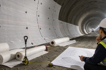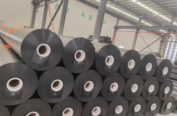

In many mined tunnel waterproofing systems, the geotextile sits between the initial lining and the waterproofing membrane. It protects the membrane from the rough lining. In a drained system, it can also help move water toward a collection drain. FTA documents a tunnel system where the geotextile performs both functions: drainage and protection of the membrane from the initial lining.[1]
Check the Shotcrete
Start with the shotcrete. If the surface underneath is poor, a thicker geotextile will not make the whole system safe.
A membrane can later be pushed back toward the primary lining by groundwater, cast-in-place concrete or other construction loads. Once that happens, even a small piece of exposed steel or a sharp aggregate point can put a high load onto a very small area.
Walk the full surface and look for:
- exposed reinforcement bars or wire mesh;
- sharp tie wire;
- nails, bolts and unused anchors;
- projecting steel fibers;
- sharp aggregate;
- hard shotcrete ridges;
- deep local hollows;
- abrupt steps;
- loose rebound;
- weak or loose repair material;
- sharp construction-joint edges;
- temporary steel parts that should have been removed.
If one of these defects is present, deal with the cause rather than covering it. Remove the sharp point, smooth the edge or repair the surface first.
| Shotcrete condition | Main risk | Action |
|---|---|---|
| Sharp aggregate | Local puncture | Grind or repair it |
| Exposed steel | Direct contact with membrane | Cut back and cover it |
| Projecting steel fiber | Small sharp contact point | Remove or cover it |
| Deep hollow | Fabric bridges the surface | Repair if outside project tolerance |
| Hard ridge | High local pressure | Smooth the transition |
| Loose shotcrete | Material can move behind the membrane | Remove and repair it |
| Flowing water | Uncontrolled water behind waterproofing | Treat or divert it |
The goal is not to make the shotcrete look like finished architectural concrete. It only needs to provide a safe base for the approved geotextile and membrane system.
Check the Surface Shape
A surface can have no obvious sharp points and still cause trouble if the overall profile is poor.
When fabric is pulled tightly across a deep hollow, it bridges the gap instead of following the shotcrete. Later loading can push the geotextile and membrane back into that hollow. The movement then ends up around fixing points and seams, exactly where you do not want extra stress.
Spend more time checking:
- crown-to-shoulder changes;
- wall-to-invert corners;
- cross-passage openings;
- niches and recesses;
- construction joints;
- drainage channels;
- pipe and service openings.
If the project specification gives a measurable surface tolerance, use that value and the inspection method stated in the project documents. A limit taken from another waterproofing system should not be carried over automatically.
On site, the checking sequence can stay simple:
- Inspect the shotcrete at close range.
- Mark defects on the surface.
- Complete the repair.
- Remove repair debris.
- Check the repaired area again.
- Release the area for geotextile installation.
Control the Water
Before deciding what to do with water on the shotcrete, confirm whether the tunnel uses a drained or undrained waterproofing system.
FTA describes drained systems as systems that allow groundwater to enter a tunnel drainage system. Undrained or closed systems are designed to keep groundwater outside the tunnel and may have to resist hydrostatic pressure.[1]
The treatment method therefore depends on the approved design. Local inflow may be handled by:
- injection;
- plugging;
- drainage strips;
- drainage mats;
- collector drains;
- temporary diversion before waterproofing.
What matters is keeping the water on the route shown in the design. A new drainage path should not be created just because it is easier for the installer.
Work should stop and the water problem should be dealt with first if it:
- runs across the membrane seam area;
- keeps carrying dirt onto the waterproofing;
- creates an uncontrolled flow behind the geotextile;
- blocks or bypasses the planned drainage route;
- prevents the approved installation method from being followed.
Check the Geotextile
GSM is useful, but it is not enough to judge whether a tunnel geotextile is suitable.
A value such as 500 g/m² tells you the mass per unit area. It does not tell you, on its own, how the material will behave against a sharp point or under a concentrated load.
When checking an approved nonwoven geotextile, look at the properties that actually affect the job.
| Property | What it tells you |
|---|---|
| Mass per unit area | Fabric weight and product identification |
| Thickness | Cushioning before compression |
| Static puncture resistance | Resistance to a concentrated load |
| Dynamic perforation resistance | Resistance to impact damage |
| Tensile strength | Strength when the material is pulled |
| Elongation | How much the material can stretch |
| In-plane water flow | Drainage performance where required |
| Durability | Suitability for the expected service conditions |
ISO 13428:2024 provides a test for geosynthetic protection efficiency against impact on a hard surface. It can also be used with the actual rigid surface and real geosynthetic layer arrangement when project-specific protection performance needs to be checked.[2]
ISO 12236:2026 measures static puncture resistance by pushing a flat-ended plunger through the geosynthetic.[3] ISO 13433:2025 covers dynamic perforation using a steel cone dropped from a fixed height.[4] ISO 10319:2024 covers the wide-width tensile test used to measure tensile force and elongation.[5]
Data sheets also need to be read on the same basis. If two products use different test methods or units, the numbers should not be compared directly. This geotextile data sheet guide explains how to check GSM, tensile strength, puncture data and hydraulic properties before comparing products.
Calculate Material Weight
GSM becomes useful when you need to estimate how much material is in a section.
1,000 m² of 500 g/m² geotextile contains about 500 kg of fabric before packaging, overlaps, trimming and waste:
1,000 m² × 0.5 kg/m² = 500 kg
For a measured installation area of 2,000 m², the theoretical fabric mass is:
2,000 m² × 0.5 kg/m² = 1,000 kg
This calculation is only about quantity. It does not tell you whether 500 g/m² provides enough protection for the tunnel.
Estimate the Geotextile Area
For a simple tunnel section, start with the waterproofed perimeter and the tunnel length.
Take this example:
- tunnel section length: 100 m;
- waterproofed perimeter: 20 m.
The measured surface area is:
100 m × 20 m = 2,000 m²
If the quantity plan uses an example allowance of 7% for overlaps, cuts and local repairs:
2,000 m² × 1.07 = 2,140 m²
The purchasing quantity in this example would therefore be about 2,140 m².
The 7% is only a calculation example. On an actual project, the allowance should come from roll width, tunnel geometry, overlap requirements, openings, installation sequence and previous site records.
| Example item | Calculation | Result |
|---|---|---|
| Tunnel length | Given | 100 m |
| Waterproofed perimeter | Given | 20 m |
| Measured area | 100 × 20 | 2,000 m² |
| Example planning allowance | 2,000 × 7% | 140 m² |
| Example order quantity | 2,000 + 140 | 2,140 m² |
| Fabric mass at 500 g/m² | 2,140 × 0.5 | 1,070 kg |
Check the Rolls
Rolls should be checked before they are taken into the work area. Damage that is easy to see outside the tunnel becomes much harder to deal with once installation has started.
Set aside material with:
- large tears;
- oil or chemical contamination;
- heavy embedded dirt;
- damage caused during transport or storage;
- incorrect product identification;
- missing batch information where traceability is required.
Geotextile rolls should not be dragged across reinforcement, sharp concrete or construction debris.
Set Out the Fixings
Fixing positions should be marked before drilling. This avoids crews building the layout one anchor at a time and gradually drifting away from the intended grid.
FTA documents one tunnel system where geotextile was fixed to the crown and side walls using a steel nail and PVC washer disc. The PVC waterproofing membrane was then heat welded to those washer discs.[1]
That is one project detail, not a general fixing rule. Fixing type and spacing should still come from the project drawings.
Before marking the grid, locate:
- tunnel centerline;
- crown reference;
- chainage;
- geotextile roll direction;
- membrane panel direction;
- drainage strips;
- collector channels;
- openings and penetrations.
Use these fixed references for setting out. Measuring every new fixing from the one installed before it can allow small errors to build up across the tunnel profile.
Plan the Fixing Density
The crown and walls do not always behave the same way. At the crown, unsupported fabric is more likely to sag under its own weight.
If there are too few effective fixing points, you may see:
- large hanging pockets;
- moving overlaps;
- poor membrane support;
- extra load on individual fixing points.
Too many unplanned fixings create a different set of problems. They can interfere with drains, produce uneven attachment lines and add unnecessary anchor holes.
The approved grid should therefore remain the starting point.
Once that spacing is known, a regular rectangular grid can be used for quantity planning:
Fixings per m² ≈ 1 ÷ (horizontal spacing × vertical spacing)
Assume an approved project drawing already specifies a grid of 1.0 m × 1.5 m.
The theoretical density would be:
1 ÷ (1.0 × 1.5) ≈ 0.67 fixings/m²
For the earlier 2,000 m² example:
2,000 × 0.67 ≈ 1,340 fixing points
This is a quantity calculation only. It does not mean 1.0 m × 1.5 m is a recommended tunnel fixing grid.
Site quantities may be higher around:
- corners;
- openings;
- crown transitions;
- repairs;
- special drainage details;
- membrane attachment details.
Avoid Fixing Conflicts
A neat grid on paper can still clash with other tunnel details. Check the location before drilling.
The fixing should not pass through:
- drainage strips;
- collector channels;
- embedded pipes;
- special penetration details;
- weak shotcrete repairs;
- membrane joint details.
If the grid meets a drain, deal with the clash using the approved detail. Crushing the drainage component or drilling through it simply creates another problem behind the waterproofing.
Check the Fixings
A fixing that looks fine from the front can still be poorly anchored.
Check for:
- fixings installed in loose rebound;
- oversized drill holes;
- incorrect anchor length;
- cracked fixing discs;
- fasteners that are not fully seated;
- anchors installed over cavities;
- fixings pressing directly onto drainage products.
Where pull-out testing is required, use the load, frequency and acceptance limit written into the project QA requirements. A value from another tunnel should not be reused without justification.
Several failures in one area are a sign to check the shotcrete rather than keep adding more anchors into the same zone.
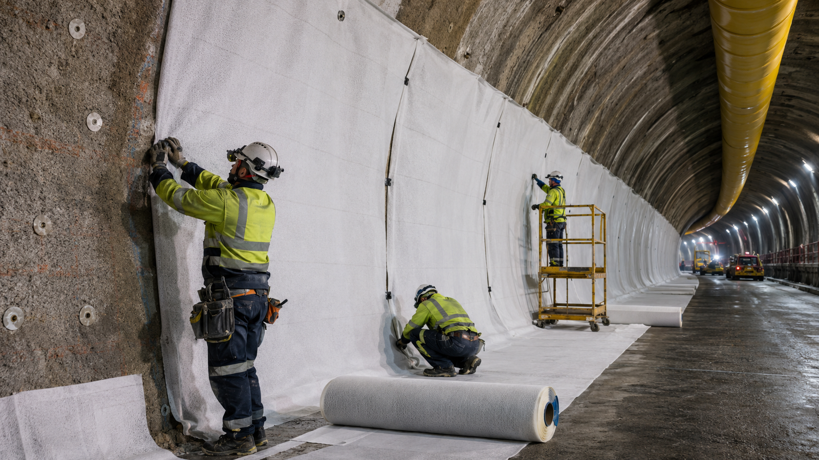
Install the Geotextile
The fabric should sit close to the accepted tunnel surface, but it should not be stretched drum-tight.
| Condition | What you see on site |
|---|---|
| Acceptable | Fabric follows the main tunnel profile and remains supported between fixings |
| Too tight | Fabric forms a straight bridge across a visible hollow |
| Too loose | Large pockets or heavy folds hang away from the surface |
There is no useful universal slack dimension because tunnel geometry and fixing layouts vary. What matters is that the geotextile follows the real surface without obvious tension or large unsupported pockets.
The same practical problems also appear in other membrane systems. Sharp surfaces, open overlaps, folds and trapped debris are covered in more detail in this geotextile cushion installation guide.
Control the Crown
Crown work is easier to control when the crew installs one manageable section at a time.
Opening a large unsupported area usually means more pulling, more movement at the overlaps and more corrections afterward.
Before moving forward, check that:
- fixings are secure;
- the fabric is not stretched across hollows;
- large hanging pockets are removed;
- overlaps are still in position;
- no temporary sharp clips remain behind the membrane.
Keep the Overlaps Closed
The main job of the geotextile joint is simple: no part of the shotcrete should be left exposed behind the waterproofing membrane.
Use the overlap stated in the project specification or approved installation method. One overlap value should not be treated as correct for every tunnel.
Look for:
- visible shotcrete between sheets;
- rolled-back edges;
- large wrinkles;
- movement at crown joints;
- sharp temporary fasteners;
- several layers building up at one point.
Calculate Effective Roll Coverage
Roll width is not the same as effective installed width once overlaps are included.
Assume a project uses:
- roll width: 4.00 m;
- approved side overlap: 0.15 m.
The approximate effective width after one side overlap is:
4.00 m − 0.15 m = 3.85 m
Ten parallel strips would therefore provide about:
10 × 3.85 m = 38.5 m
of effective width before outer edges, local cuts or irregular tunnel geometry are taken into account.
The 0.15 m overlap here is only a calculation example. The real geotextile overlap should come from the project documents.
Membrane seam overlap and geotextile overlap are also not the same thing. FTA documents one PVC tunnel membrane system using a minimum membrane overlap of 6 in., or about 0.15 m. That value belongs to the PVC membrane in that project and is not automatically a geotextile overlap requirement.[1]
Avoid Thick Joints
More layers do not always mean more protection. A thick pile of fabric can create a hard change in the support surface behind the membrane.
This usually happens when:
- two overlaps cross;
- a repair patch is placed directly over an overlap;
- several cut pieces meet at one corner;
- excess fabric is folded instead of arranged properly.
Roll positions should be planned so these local build-ups are reduced where possible.
Keep the Drains Open
In a drained tunnel, a well-protected membrane is not enough if the drainage path has been blocked during installation.
After the geotextile is in place, check that:
- drainage strips are continuous;
- fixings have not crushed them;
- collector openings remain clear;
- fabric is not folded into an outlet;
- cutting and shotcrete debris has been removed;
- connections to the main collection system remain open.
Water passing through the fabric and water moving along the plane of the material are two different properties. Where in-plane drainage matters, it should be checked under conditions relevant to the actual drainage system. ISO 12958-2:2020 provides a performance test for in-plane water flow using boundary materials, normal loads and other test conditions of interest.[6]
Handle Corners and Openings
Flat rolls do not naturally fit every recess, opening and inside corner in a tunnel.
The problem is most obvious around:
- niches;
- cross-passages;
- deep recesses;
- invert corners;
- drain outlets;
- pipes and other penetrations.
Forcing one large piece into a deep corner usually pushes the extra material somewhere else and creates a fold or thick area.
Where the approved method allows it, planned cuts and separate pieces with controlled overlaps are easier to manage. The shotcrete still needs to remain fully covered behind the membrane.
Repair Geotextile Damage
A torn geotextile should not be patched until the cause is known.
- Expose the full damaged area.
- Check the shotcrete underneath.
- Remove any sharp point or loose material.
- Check the fabric around the tear.
- Install the approved patch.
- Maintain the required overlap around the damaged area.
- Secure the patch using the approved method.
- Inspect it before membrane work starts.
A patch fixes the damaged fabric. It does not fix the sharp surface that caused the damage.
If the same area keeps tearing, stop adding patches and go back to the substrate.
Track Repair Density
Repair numbers can be useful when they are treated as a trend rather than a pass/fail limit.
If a 500 m² completed section contains 15 geotextile repairs:
15 ÷ 500 × 100 = 3 repairs per 100 m²
This number is not a pass/fail limit. There is no universal rule saying that three repairs per 100 m² is acceptable or unacceptable.
The useful part is comparison. If nearby sections usually need far fewer repairs and one area suddenly rises to 3, 5 or more repairs per 100 m², something has changed on site.
Possible causes include rougher shotcrete, exposed steel fibers, poor handling, fixing problems or a different work crew.
Tracking repair density by chainage makes those changes easier to spot before the membrane hides the work.
Inspect Before the Membrane
This is the last chance to see the complete geotextile layer before it disappears behind the waterproofing membrane.
| Item | Accept before covering |
|---|---|
| Shotcrete | No unacceptable sharp or loose areas |
| Steel | No exposed sharp ends |
| Water | Active inflow is controlled |
| Geotextile | Correct approved material |
| Coverage | No visible shotcrete gaps |
| Fixings | Correct type, position and condition |
| Crown | No large unsupported pockets |
| Overlaps | Continuous and reasonably flat |
| Repairs | Complete and secure |
| Drainage | Open and undamaged |
| Work area | No sharp debris trapped on the fabric |
An area should not be released when exposed steel, unstable shotcrete, uncontrolled water, an open geotextile joint, repeated tearing, loose fixings or blocked drainage is still present.
Install the Waterproofing Membrane
The membrane should follow the tunnel profile without being pulled unnecessarily tight between fixing points.
The quality of the geotextile work directly affects this stage. Large fabric folds change the membrane shape. Loose fibers and dirt can get into seam areas. Water that was not controlled earlier can interfere with joining and inspection.
Membrane joining areas should therefore remain clean and meet the conditions required by the approved membrane procedure.
Welding temperature, speed, seam-test pressure and acceptance limits should not be copied from another membrane type. PVC, TPO, HDPE and other sheet systems can use different installation and test procedures.
Protect the Membrane
Once the membrane is installed, the main damage risk moves to its exposed side. The geotextile behind it cannot protect against everything happening in front of it.
Common damage sources include:
- reinforcement bar ends;
- tie-wire tails;
- reinforcement chairs;
- dropped tools;
- temporary steel supports;
- formwork parts;
- scaffold parts;
- hot-work sparks;
- traffic over the invert;
- concrete placement equipment.
FTA documents additional protective measures used to protect waterproofing during reinforcement installation, formwork erection and concrete placement. The same source also describes extra protection where nearby welding could expose waterproofing to sparks and high temperature.[1]
Control Reinforcement Work
Reinforcement work deserves another membrane check because this is where many concentrated contact points are introduced.
Make sure:
- bar ends do not press against the membrane;
- tie-wire tails face away from the waterproofing;
- chairs and spacers use the approved support detail;
- steel is not dragged across the membrane;
- temporary supports do not create sharp contact points;
- hot work is properly shielded.
If several punctures keep appearing in the same place, repairing each hole is not enough. The reinforcement support or working method causing the damage needs to be corrected.
Protect the Invert
The invert usually gets much more traffic than the crown or walls, so it needs closer control once the membrane is exposed.
It may be used for:
- walking traffic;
- reinforcement work;
- material storage;
- equipment movement;
- dropped tools;
- construction debris.
The protection layer shown on the project drawings should be installed before heavy work begins. Depending on the system, this may be a protection geotextile, board, sheet, screed or another approved layer.
Check Penetrations
Pipes, ducts, drains, instruments and structural inserts should have a waterproofing detail before the membrane reaches them.
Cutting a hole first and deciding how to seal it afterward leaves too much to site improvisation.
The detail may use:
- prefabricated collars;
- compatible membrane pieces;
- waterstops;
- clamping systems;
- welded sleeves;
- other designed seals.
The geotextile around the penetration should be arranged at the same time so the shotcrete remains covered without creating a thick pile of fabric layers.
Check Before Concrete
A membrane that was sound before reinforcement work may not still be sound when concrete placement begins.
Check it again after reinforcement, access, formwork and temporary work have been completed.
Look at:
- visible punctures or tears;
- repairs;
- reinforcement contact points;
- invert protection;
- penetrations;
- areas used for access;
- areas exposed to hot work;
- construction debris.
Any repair and required QA should be completed before the waterproofing becomes inaccessible.
Find the Cause of Damage
| Site problem | Check first | Action |
|---|---|---|
| Geotextile keeps tearing | Sharp shotcrete or steel | Repair the substrate before patching again |
| Large pocket at crown | Fixing layout and installation sequence | Correct the affected section |
| Fabric bridges a hollow | Too much tension | Release and refit the fabric |
| Shotcrete visible between sheets | Overlap movement | Restore continuous coverage |
| Loose fixing disc | Anchor or weak shotcrete | Replace and inspect nearby fixings |
| Drainage strip flattened | Fixing position or fabric fold | Restore the drainage path |
| Repeated membrane holes at invert | Traffic or inadequate protection | Change the protection method before continuing |
| Damage beside reinforcement | Bar, wire or spacer contact | Correct the steel support and repair the membrane |
Track Material Loss
Instead of assuming one fixed waste percentage, compare the material issued with the amount actually installed and the usable material left over.
For example:
- geotextile issued to the section: 2,160 m²;
- installed area plus reusable material remaining: 2,030 m².
The recorded cutting and installation loss is:
(2,160 − 2,030) ÷ 2,160 × 100 ≈ 6.0%
This does not mean 6% is a normal or acceptable tunnel loss. It is more useful as a project-to-project or section-to-section comparison.
If the loss rises sharply, check:
- roll layout;
- excessive trimming;
- too many small pieces around openings;
- damaged rolls;
- repeated repair patches;
- poor material handling.
Keep Useful Records
Once the final lining is in place, a note such as “membrane repaired” is not enough to find the same location again.
Useful records can include:
- tunnel chainage;
- clock position or tunnel side;
- section number;
- installation date;
- measured installation area;
- geotextile batch or roll number;
- fixing quantity where tracked;
- water-treatment locations;
- number of geotextile repairs;
- membrane repairs;
- required seam-test results;
- final inspection status.
A record such as “Chainage 1+245, 2 o’clock, approximately 120 mm damaged area, repaired and retested” is much more useful than writing only “membrane repaired.”
For larger sections, figures such as installed m², fixing count and repairs per 100 m² also make it easier to compare work quality between chainages.
FAQ
Should crown and wall fixing spacing always be the same?
No. Gravity, tunnel shape, roll layout and the membrane fixing system can change the support needed at different parts of the tunnel. Use the approved fixing drawing rather than copying one spacing value across the whole profile.
Can heavier geotextile make rough shotcrete acceptable?
Not by itself. Extra fabric may provide more cushioning, but exposed steel, unstable shotcrete and sharp projections still need to be corrected. Protection performance should be checked against the real surface and loading rather than using GSM alone.[2]
What should be done if geotextile keeps tearing?
Stop work and inspect underneath it. Repeated tearing normally means the cause is still present, such as sharp aggregate, exposed steel, a bad fixing or rough handling. Remove the cause before repairing the geotextile.
How much geotextile should be ordered?
Start with the measured waterproofed area, then add the effect of the actual roll layout, approved overlaps, cuts, openings and expected repairs. A 100 m section with a 20 m waterproofed perimeter equals 2,000 m² before allowances. One fixed waste percentage should not be applied to every tunnel.
When is the final membrane inspection needed?
Inspect after membrane installation and again after reinforcement and other work that could damage it. The last check should happen before concrete or another permanent layer makes the membrane inaccessible.
Finally
A good tunnel geotextile installation is easier to control when the site team uses both visual checks and simple project data. A 100 m section with a 20 m waterproofed perimeter contains about 2,000 m² of surface, while 500 g/m² geotextile contains about 500 kg of fabric per 1,000 m². Fixing quantities should be calculated only after the approved spacing is known, and overlaps need to be included in material planning. Tracking repairs per 100 m² can also show when one chainage is performing worse than the sections around it. These numbers help with planning and QA, but the final acceptance still depends on the approved waterproofing design, shotcrete condition, drainage arrangement and membrane system.