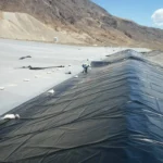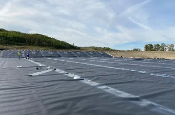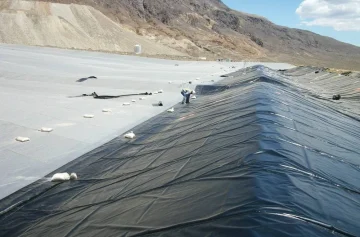
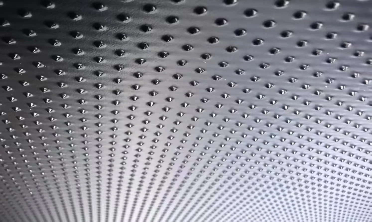
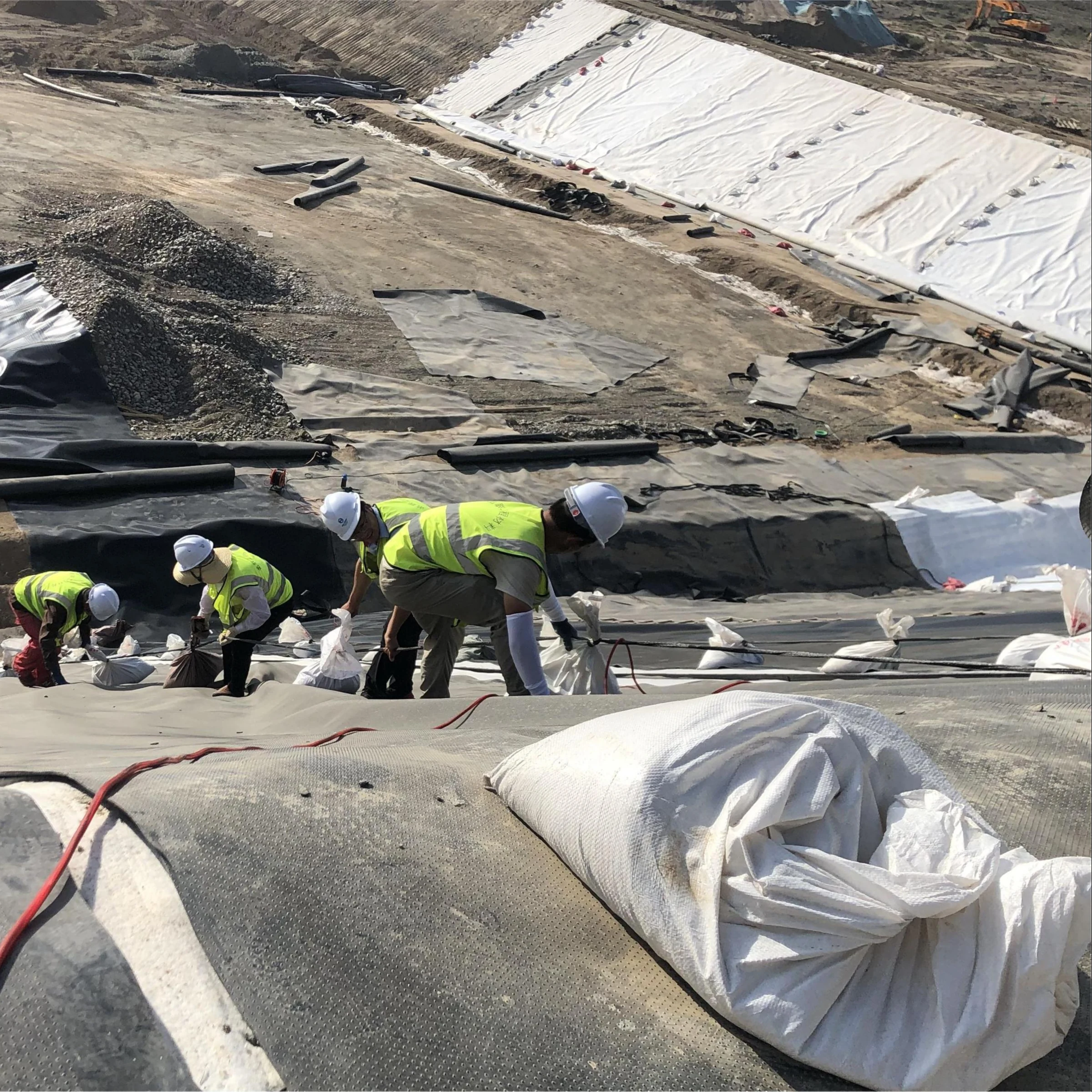
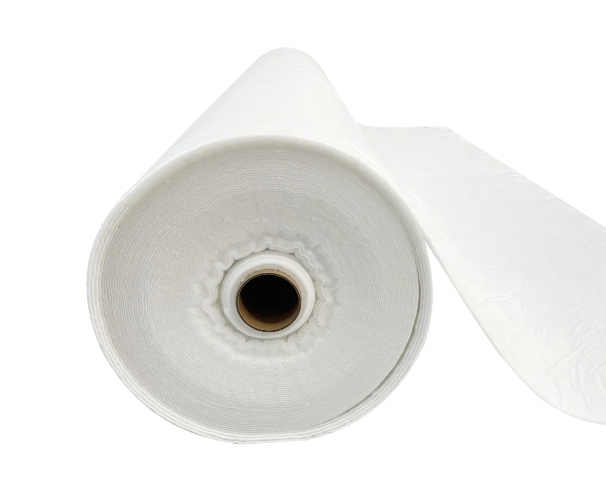

Seal a geomembrane pipe penetration with a fitted boot: join its skirt to the liner, seal its neck to the pipe, and support the pipe independently. For HDPE, the skirt is commonly extrusion-welded and the neck sealed with a gasket and clamps or an engineered flange connection. Before covering, inspect the boot seams, test accessible welds using the specified method, and verify the neck seal separately. Leave enough flexibility for the movement defined in the design.
Boot Dimensions and Fit
Measure the pipe’s outside diameter and penetration angle before preparing the boot pattern. Record ribs, coatings, raised welds, and ovality. Nominal pipe size alone is not enough to size the neck.
| Detail | Example or Check | Installation Requirement |
|---|---|---|
| Neck circumference | A 200 mm outside diameter gives a circumference of about 628 mm. An extra 10 mm in diameter adds about 31 mm. | Add the specified seam and forming allowances to the cutting pattern. |
| Angled penetration | At 45° from the liner’s normal—the line perpendicular to its surface—the ideal intersection has a major axis about 1.41 times the pipe diameter. | For a 200 mm pipe, that axis is about 283 mm. Use the approved detail for the actual opening and boot shape. |
| Skirt clearance | Check access behind the pipe and at corners. | Leave room for welding, testing, and repairs. Support the seam area without voids beneath it. |
| Trial fit | Look for a taut section opposite a folded or bunched section. | Correct the pattern or alignment rather than stretching the boot into place. |
| Installation access | Check whether the boot can slide over an accessible pipe end. | If neither end is accessible, use an approved field-fabricated or field-closed detail. |
Specify the boot material and thickness alongside the HDPE liner specification. Skirt width, overlap, and effective weld width are separate dimensions; show each on the connection detail.
Pipe and valve loads belong on supports or foundations. Complete alignment adjustments before sealing the boot. Where settlement or thermal movement is expected, define its direction and range, including rotation where relevant. Extra loose membrane does not, by itself, establish an allowable movement.
Pressure at the Penetration
Use the liquid depth above the penetration, not the pond’s total capacity, to calculate static pressure. For an open freshwater surface, p=ρgh gives:
| Liquid | Depth Above Penetration | Approximate Static Gauge Pressure |
|---|---|---|
| Freshwater, 1,000 kg/m³ | 1 m | 9.8 kPa |
| Freshwater, 1,000 kg/m³ | 3 m | 29.4 kPa |
| Freshwater, 1,000 kg/m³ | 5 m | 49.1 kPa |
| Process liquid, 1,200 kg/m³ | 3 m | 35.3 kPa |
If groundwater or another pressure acts on the opposite side, calculate the pressure difference across the liner. Include any specified transient loads. The boot seals around the outside of the pipe; it does not repair a leaking pressure pipe or pipe joint.
These calculations use a gravitational acceleration of 9.81 m/s². They are not connection ratings or test pressures. The geometry examples above exclude fabrication allowances.
Sealing Methods
For mechanically attached details, review ASTM D6497/D6497M alongside the approved connection drawing. A generic boot illustration does not define gasket material, clamp torque or a pressure rating.
| Method | Where It Fits | Checks and Limits |
|---|---|---|
| Welding | Boot-to-liner seams in compatible, weldable materials. | Verify material identification, surface preparation, and trial-weld results. Pipe and liner resins can differ, so “both are HDPE” is not sufficient evidence for direct welding to the pipe.[1] |
| Clamps and gasket | Boot necks on pipe surfaces that provide continuous circumferential contact. | Check clamp quantity, width, position, and specified torque. Inspect for folds, gasket extrusion, sharp edges, and pipe deformation. Corrugated pipes need a suitable sealing transition or fitting. |
| Flange connection | Details with designed mating faces, gaskets, and fasteners. | Check face condition, gasket alignment, bolt installation, and tightening records. The design must address flange stiffness, membrane stresses, and long-term deformation. |
| Adhesive or tape | Membrane systems approved for these joining methods. | Use the specified primer, adhesive, or tape and surface preparation. Do not assume general-purpose construction adhesive is suitable for HDPE. |
For wastewater and secondary containment applications, provide the liquid composition, concentration, and temperature range. Check compatibility for the membrane, welding material, gasket, sealant, and metal components—not just the main liner.
Inspection and Testing
Visual Checks
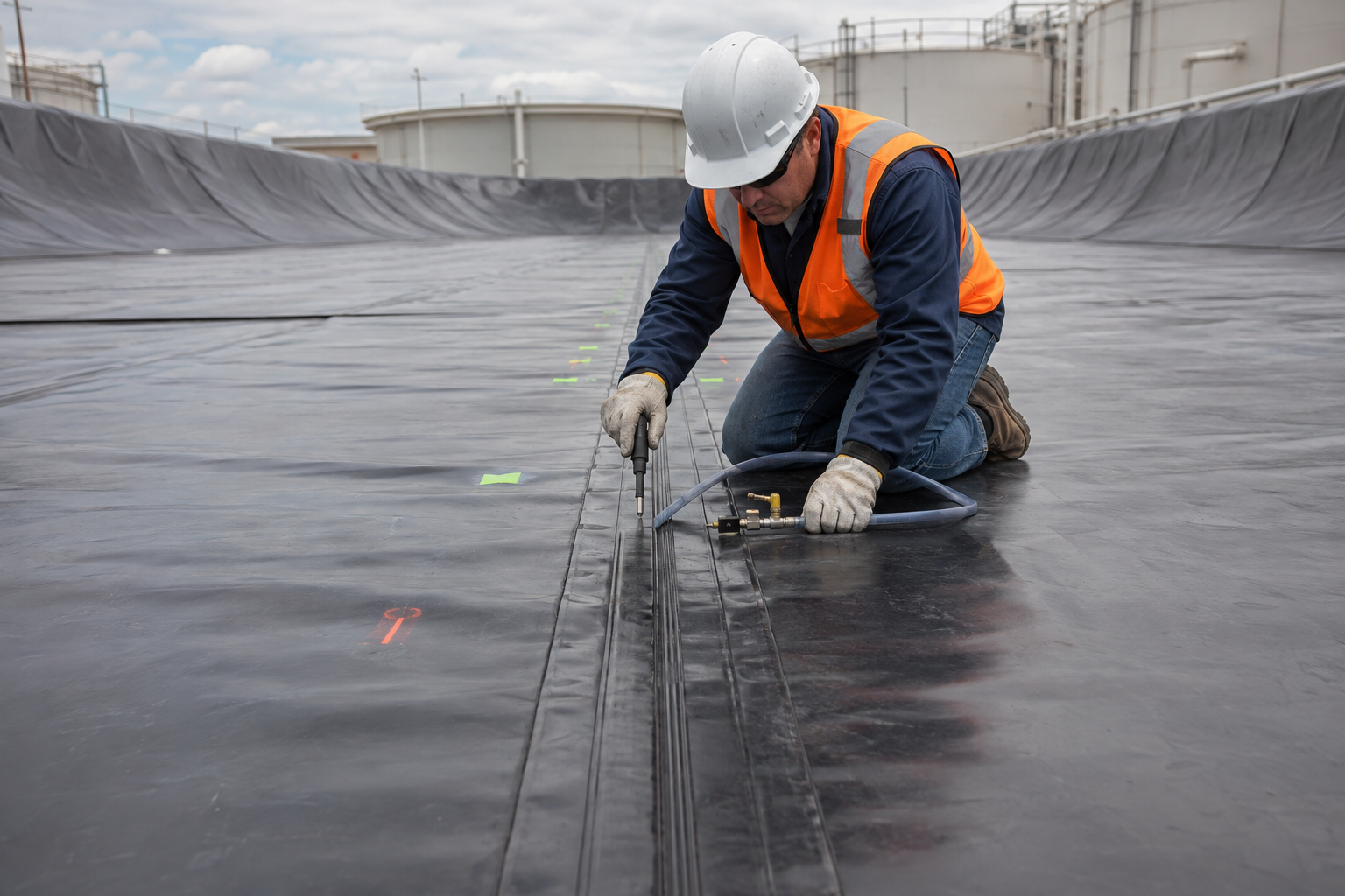
Inspect the skirt weld, boot fabrication seams, corners, and weld start-and-stop points. Mark open folds or “fishmouths,” separated edges, burns, punctures, and wrinkles crossing the seal. At the neck, check gasket position, clamp alignment, and membrane damage. For prefabricated boots, review fabrication inspection records and look for shipping damage.
Seam Integrity
Electrical tests must be performed by trained personnel under the method-specific electrical safety procedure. Isolate the work area and address water, grounding and ignition hazards before testing.
Select the test method for the seam geometry and material. ASTM D4437/D4437M outlines nondestructive seam-testing options; the project specification defines which methods and acceptance criteria apply.[2]
| Method | Required Conditions | Limitations |
|---|---|---|
| Vacuum box | The box must seal around the test area. | Curves and tight corners may prevent a valid test. |
| Air-channel pressure test | A dual-track seam must have a continuous, testable air channel. | This method does not apply to a standard single extrusion weld. |
| Seam spark test | The detail must provide the required conductive material or path. Follow the specified voltage and probe-distance procedure. | Conductive material may need to be placed during fabrication. Do not test where sparks could ignite surrounding materials.[3] |
| Electrical leak location | The liner system must meet the selected method’s conductivity and isolation requirements. | Penetrations and flange bolts can create electrical bypass paths that mask leaks; these paths require isolation or insulation.[4] |
Mark tested sections and results on the connection drawing. Record the location and length of any untested section, then resolve it with an approved alternative method or a revised detail. An inaccessible seam is not a passed seam.
Seam Strength
Leak testing does not measure weld strength. For thermally joined, nonreinforced geomembranes, ASTM D6392 provides peel and shear procedures for assessing seam quality.[5] Set sampling locations and repair procedures in the quality plan before cutting into finished work.
Neck Seal
Check the neck assembly against the drawing and complete the specified connection leak verification or system test. Skirt weld results do not verify the gasket, clamps, or flange. Test pressure, liquid level, and duration must come from the approved procedure.
For a water-holding test, a 1 mm level change over approximately 100 m² represents about 100 L. Record inflows, outflows, rainfall, evaporation, and measurement uncertainty before treating a level change as leakage.
Leak Investigation and Repairs
- Water at the neck: Confirm the entry path before dismantling the connection. Check gasket joints, folds, clamp alignment, and pipe grooves.
- An open skirt seam: Check for fishmouths, poor bonding, and tension in the surrounding sheet. Correct the cause before repairing the seam.
- Damage beneath a clamp: Look for sharp edges, excessive tightening, or gasket displacement. Further tightening can enlarge the damage.
- Cracking after startup: Compare pipe elevations and clamp positions with installation records. Check measured movement against the design allowance.
- Leakage after backfilling: Inspect for punctures, concentrated fill loads, and pipe displacement.
- Repeated leakage after sealant repairs: Check the skirt, neck, pipe, and wall penetration separately. The visible outlet may be some distance from the leak’s entry point.
Acceptance Before Covering
Use a unique penetration ID to link the drawing, material identification, installation records, test results, and neck-seal verification. Keep manufacturing quality-control records separate from field acceptance results.
Record each repair location, method, and retest result. Label photos with the viewing direction and include a scale in defect close-ups. Complete acceptance sign-off before covering. Where the pipe also passes through concrete, inspect the pipe-to-wall seal separately.
References and Project Applicability
Use these references to check the relevant methods and documentation. The approved drawings, contract specification and project quality plan govern acceptance. This article does not replace a site-specific design or signed inspection record.
- ASTM D6497/D6497M-02(2025) — Mechanical attachment to penetrations or structures
- U.S. EPA — Inspection Techniques for the Fabrication of Geomembrane Field Seams
- ASTM D4437/D4437M-16(2023) — Nondestructive seam integrity testing
- ASTM D6365-26 — Nondestructive seam testing using the spark test
- ASTM D6747-25 — Selecting electrical leak location techniques
- ASTM D6392-25 — Peel and shear testing of thermally fused nonreinforced geomembrane seams